EP2099217A2 - Procédé de sélection de mode et appareil d'affichage le comportant - Google Patents
Procédé de sélection de mode et appareil d'affichage le comportant Download PDFInfo
- Publication number
- EP2099217A2 EP2099217A2 EP08171307A EP08171307A EP2099217A2 EP 2099217 A2 EP2099217 A2 EP 2099217A2 EP 08171307 A EP08171307 A EP 08171307A EP 08171307 A EP08171307 A EP 08171307A EP 2099217 A2 EP2099217 A2 EP 2099217A2
- Authority
- EP
- European Patent Office
- Prior art keywords
- source
- mode
- input
- display apparatus
- image
- Prior art date
- Legal status (The legal status is an assumption and is not a legal conclusion. Google has not performed a legal analysis and makes no representation as to the accuracy of the status listed.)
- Ceased
Links
Images


Classifications
-
- H—ELECTRICITY
- H04—ELECTRIC COMMUNICATION TECHNIQUE
- H04N—PICTORIAL COMMUNICATION, e.g. TELEVISION
- H04N5/00—Details of television systems
- H04N5/44—Receiver circuitry for the reception of television signals according to analogue transmission standards
- H04N5/46—Receiver circuitry for the reception of television signals according to analogue transmission standards for receiving on more than one standard at will
-
- H—ELECTRICITY
- H04—ELECTRIC COMMUNICATION TECHNIQUE
- H04N—PICTORIAL COMMUNICATION, e.g. TELEVISION
- H04N5/00—Details of television systems
- H04N5/44—Receiver circuitry for the reception of television signals according to analogue transmission standards
-
- H—ELECTRICITY
- H04—ELECTRIC COMMUNICATION TECHNIQUE
- H04N—PICTORIAL COMMUNICATION, e.g. TELEVISION
- H04N21/00—Selective content distribution, e.g. interactive television or video on demand [VOD]
- H04N21/40—Client devices specifically adapted for the reception of or interaction with content, e.g. set-top-box [STB]; Operations thereof
- H04N21/41—Structure of client; Structure of client peripherals
- H04N21/4104—Peripherals receiving signals from specially adapted client devices
- H04N21/4113—PC
-
- H—ELECTRICITY
- H04—ELECTRIC COMMUNICATION TECHNIQUE
- H04N—PICTORIAL COMMUNICATION, e.g. TELEVISION
- H04N21/00—Selective content distribution, e.g. interactive television or video on demand [VOD]
- H04N21/40—Client devices specifically adapted for the reception of or interaction with content, e.g. set-top-box [STB]; Operations thereof
- H04N21/43—Processing of content or additional data, e.g. demultiplexing additional data from a digital video stream; Elementary client operations, e.g. monitoring of home network or synchronising decoder's clock; Client middleware
- H04N21/442—Monitoring of processes or resources, e.g. detecting the failure of a recording device, monitoring the downstream bandwidth, the number of times a movie has been viewed, the storage space available from the internal hard disk
- H04N21/44231—Monitoring of peripheral device or external card, e.g. to detect processing problems in a handheld device or the failure of an external recording device
-
- H—ELECTRICITY
- H04—ELECTRIC COMMUNICATION TECHNIQUE
- H04N—PICTORIAL COMMUNICATION, e.g. TELEVISION
- H04N21/00—Selective content distribution, e.g. interactive television or video on demand [VOD]
- H04N21/40—Client devices specifically adapted for the reception of or interaction with content, e.g. set-top-box [STB]; Operations thereof
- H04N21/47—End-user applications
- H04N21/485—End-user interface for client configuration
-
- H—ELECTRICITY
- H04—ELECTRIC COMMUNICATION TECHNIQUE
- H04N—PICTORIAL COMMUNICATION, e.g. TELEVISION
- H04N5/00—Details of television systems
- H04N5/44—Receiver circuitry for the reception of television signals according to analogue transmission standards
- H04N5/445—Receiver circuitry for the reception of television signals according to analogue transmission standards for displaying additional information
Definitions
- the present invention relates to a display apparatus, and more particularly to a display apparatus such as a TV or a monitor, which provides a displayed image to a user.
- TV performs not only a function of receiving a broadcast conventionally but also a function of a monitor in a PC. The era that only a monitor displays an image received from a PC is gone.
- An aspect of the present invention is to provide mode conversion methods and display apparatuses which are able to convert a mode automatically based on an external input status through external input units.
- a mode conversion method of a display apparatus comprising determining whether there is input of an image signal from a first source continuously during the display apparatus operation in a first mode in which the display apparatus displays the image inputted from the first source, and converting to a second mode in which the display apparatus displays an image inputted from a second source if there is no input of the image signal from the first source.
- the converting in the mode conversion method may be performed automatically without a user's input to command conversion to the second mode.
- the first source may be a personal computer (PC) and there is no input of the image signal from the first source if there is input of an image signal which does not have a synchronizing signal according to the Display Power Management Signaling (DPMS) function of the PC.
- the second source may be one of a source a user selects among sources which are able to provide an image signal and a source providing a broadcasting image signal.
- a mode conversion method of a display apparatus comprising determining whether there is input of an image signal from a first source during the display apparatus operation in a second mode in which the display apparatus displays an image input from a second source, and converting to a first mode in which the display apparatus displays the image input from the first source if there is input of the image signal from the first source.
- the mode conversion method of a display apparatus may comprises determining whether there is input of an image signal from a first source during the display apparatus operation in a second mode in which the display apparatus displays an image input from a second source, and converting to a mode in which the display apparatus displays the image input from the first source and the image input from the second source together if there is input of the image signal from the first source.
- the first source may be a personal computer (PC) and there is input of the image signal from the first source if the PC which is turned on already is connected to the display apparatus or the PC which is connected to the display apparatus already is turned on.
- a display apparatus comprising a display unit which displays an image, and a control unit which determines whether there is input of an image signal from a first source continuously during display apparatus operation in a first mode in which the display apparatus displays the image input from the first source, and converts to a second mode in which the display apparatus displays an image input from a second source if there is no input of the image signal from the first source.
- the control unit may convert to the second mode automatically without a user's input to command conversion to the second mode.
- the first source may be a personal computer (PC) and there is no input of the image signal from the first source if there is input of an image signal which does not have a synchronizing signal according to the Display Power Management Signaling (DPMS) function of the PC.
- the second source may be one of a source a user selects among sources which are able to provide an image signal and a source providing a broadcasting image signal.
- a display apparatus comprising a display unit which displays an image, and a control unit which determines whether there is input of an image signal from a first source during display apparatus operation in a second mode in which the display apparatus displays an image input from a second source, and converts to a first mode in which the display apparatus displays the image input from the first source if there is input of the image signal from the first source.
- the display apparatus may comprise a display unit which displays an image, and a control unit which determines whether there is input of an image signal from a first source during the display apparatus operation in a second mode in which the display apparatus displays an image input from a second source, and converts to a mode in which the display apparatus displays the image input from the first source and the image input from the second source together if there is input of the image signal from the first source.
- the first source may be a personal computer (PC) and there is input of the image signal from the first source if the PC which is turned on already is connected to the display apparatus or the PC which is connected to the display apparatus already is turned on.
- a display apparatus comprising external input units which receive image signals from external sources, a memory which stores a final mode which is a mode at the time when the display apparatus turned off last time, a GUI generating unit, a display unit which displays an image, and a control unit which controls the display unit to operate in a personal computer (PC) mode that is a mode which displays an image received from a PC through one of the external input units, if the final mode is the PC mode and there is input of the PC image signal.
- PC personal computer
- the control unit may check whether there is an input signal through the other external input units than the external input unit connected to the PC and controls the GUI generating unit to generate a mode selection list which shows the list of the external input units which receives the input signal, if the final mode is the PC mode and there is no input of the PC image signal.
- the control unit may control the GUI generating unit to generate a message asking whether a user want a PC mode, if the final mode is not the PC mode and there is input of the PC image signal.
- the control unit may control the display unit to operate in the final mode, if the final mode is not the PC mode and there is no input of the PC image signal or the user responds negative answer to the message.
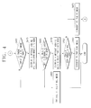
- FIG. 1 is a block diagram of a Digital TV (DTV) according to an exemplary embodiment of the present invention.
- the DTV may be connected to a Personal Computer (PC) and may convert a mode automatically according to existence of an image received from the PC.
- PC Personal Computer
- the DTV includes a broadcast receiving unit 110, an external input unit 120, an AV processing unit 130, a Graphic User Interface (GUI) generating unit 140, a video output unit 150, an audio output unit 160, a control unit 170, a memory 180, and a user input unit 190.
- GUI Graphic User Interface
- the broadcast receiving unit 110 receives a broadcasting signal from a broadcasting station or a satellite by a cable or wireless transmission and demodulates the signal.
- the external input unit 120 is connected to an external device such as a Digital Versatile Disk (DVD) player, a Divx player, and a PC and receives an external input signal from the external device.
- the external input unit 120 has terminals for connecting to the external device, for example, a composite terminal, a component terminal, a D-sub terminal, and a High Definition Multimedia Interface (HDMI) terminal.
- HDMI High Definition Multimedia Interface
- the AV processing unit 130 performs signal processing such as video decoding, video scaling, and audio decoding for the broadcasting signal received through the broadcast receiving unit 100 and the external input signal received through the external input unit 120.
- the AV processing unit 130 sends a video signal to the GUI generating unit 140 and an audio signal to the audio output unit 160.
- the GUI generating unit 140 generates a GUI to be displayed on a display and adds the generated GUI to the video signal output from the AV processing unit 130.
- the control unit 170 controls a GUI generating operation of the GUI generating unit 140.
- the video output unit 150 displays the video to which the GUI generated by the GUI generating unit 140 is added on the display.
- the audio output unit 160 outputs the audio output from the AV processing unit 130 through a speaker.
- the control unit 170 controls overall operations of the DTV according to a user's manipulation input through the user input unit 190.
- the user input unit 190 comprises various kinds of manipulation means provided in the exterior of the DTV and a light sensor which receives a user's command from a remote controller and sends the user's command to the control unit 170.
- the memory 180 stores software programs and data which is needed for the control unit 170 to control the operations of the DTV.
- mode data which is needed to control the operations of the DTV.
- the mode data includes information of a final mode which is a mode at the time when the DTV turns off.
- the control unit 170 determines whether the D-sub terminal provided in the external input unit 120 receives a normal image signal from the PC. If the image signal received from the PC has both a Horizontal Synchronizing signal (H-Sync) and a Vertical Synchronizing signal (V-Sync), it is a normal image signal. If the image signal received from the PC does not have any one of the H-Sync and the V-Sync, it is considered to be an abnormal image signal. If the abnormal image signal is received, an image signal is not regarded as having been received from the PC. If the image signal received from the PC doesn't have any one of the H-Sync and the V-Sync according to the Display Power Management Signaling (DPMS) function of PC, an image signal is not regarded as having been received from the PC. The control unit 170 may convert a mode of the DTV automatically based on whether the D-sub terminal receives an image signal from the PC. This will be explained in detail referring to FIG. 2 .
- H-Sync Horizontal Synchronizing signal
- V-Sync Vertical
- FIG. 2 is a flow chart of a mode conversion method in the DTV illustrated in FIG. 1 .
- the control unit 170 checks the memory 180 (S220).
- the control unit 170 reads data including mode data, which is stored in the memory 180 and may recognize what is the final mode of the DTV using the mode data.
- a PC mode is a mode wherein a PC image signal received from a PC which is connected to a terminal of the external input unit 120, is displayed on the DTV. If the final mode is the PC mode (S230-Y), the control unit 170 determines whether the external input unit 120 receives the PC image signal (S240).
- control unit 170 determines whether the external input unit 120 receives the PC image signal according to whether the D-sub terminal of the external input unit 120 receives the PC image signal comprising H-Sync and V-Sync.
- the control unit 170 controls the DTV to operate in the PC mode (S250).
- the control unit 170 controls the AV processing unit 130 to process the PC image signal input to the external input unit 120 and controls the video output unit 150 and the audio output unit 160 to output a PC image and sound.
- FIG. 3A illustrates the DTV performing the operation S250.
- the control unit 170 checks whether there is other external input to the external input unit 120 (S260). For example, the control unit 170 checks whether there is an external signal inputted through other external terminals such as a composite terminal, a component terminal, and HDMI terminal, if there is no external signal inputted through the D-sub terminal from the PC.
- control unit 170 makes a mode selection list based on the result of the check in operation S260 and controls the GUI generating unit 140 to make a GUI for the mode selection list (S280).
- the mode selection list includes all the modes which a user can select. TV and names of terminals which receives an external signal are included in the list.
- FIG. 3B illustrates an example of a mode selection list. A user can select one of the modes in the mode selection list illustrated in FIG. 3B using the user input unit 190.
- the control unit 170 controls the DTV to convert its mode to the mode selected by a user (S290).
- FIG. 3C illustrates the DTV which performs operation S290, if a user selects a component mode.
- control unit 170 controls the DTV to convert to the TV mode (S300).
- the control unit 170 updates the information of a final mode in the mode data stored in the memory 180 from PC mode to TV mode.
- the control unit 170 controls the GUI generating unit 140 to display a message that says 'converted to TV mode'.
- the DTV displays the message illustrated in FIG. 3D .
- the control unit 170 controls the AV processing unit 130 to process the broadcasting signal received at the broadcast receiving unit 110 and controls the video output unit 150 and the audio output unit 160 to output a broadcasting image and sound.
- FIG. 3E illustrates the DTV which displays the broadcasting image.
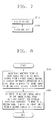
- FIG. 4 is a flow chart of operations in case a final mode is not a PC mode in operation 230 of FIG. 2 .
- the control unit 170 determines whether there is a PC image signal input to the external input unit 120 (S410).
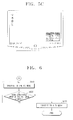
- FIG. 5A illustrates a DTV which displays a message asking whether a user wants to convert to a PC mode. A user may indicate whether he chooses a PC mode, by responding to the displayed message.
- the control unit 170 controls the GUI generating unit 140 to display a message asking which display type a user wants S440.
- FIG. 5B illustrates a DTV which display a message asking which display type a user wants. A user may choose a display type he wants, by responding to the displayed message.
- a dual mode is a mode which displays a PC image and the image of the final mode found in the checking operation S220 together. If a user chooses the dual mode (S450-Y), the control unit 170 controls the DTV to convert its display type to the dual mode (S460).
- FIG. 5C illustrates a DTV which is converted to the dual mode if the final mode is a TV mode.
- control unit 170 controls the DTV to convert its mode to the PC mode (S470).
- control unit 170 controls the DTV to operate in the final mode found in the operation S220 (S480).
- FIG. 6 is a flow chart of the DTV's operations after the DTV converts its mode to the PC mode through the operation S250 of FIG. 2 or the operation S470 of FIG. 4 .
- control unit 170 determines whether there is a continuous input of a PC image signal to the external input unit 120 (S620).
- the DTV If there is a continuous input of a PC image signal (S620-Y), the DTV operates the operation S610. But if there no continuous input of a PC image signal (S620-N), the control unit 170 controls the DTV to convert its mode to the TV mode (S630).
- a method for converting a mode automatically depending on whether there is input of a PC image signal and a DTV which performs the method is explained with an exemplary embodiment.
- a mode is converted depending on whether there is input of a PC image signal in this embodiment, but it is possible that a mode is converted depending on whether there is input of an image signal from a source other than a PC. For example, it is possible to implement a mode which is converted depending on whether there is input of an image signal from a DVD player through the component terminal.
- the PC is connected to the DTV through the D-sub terminal in this embodiment, but it is possible that the PC is connected to the DTV through other terminals such as the DVI terminal.
- the example of the case that there is input of the PC image signal is that the PC which is already turned on, is connected to the DTV or that the PC which is already connected to the DTV, is turned on.
- the TV mode in the operation S300 of FIG. 2 and the operation S630 of FIG. 6 may be substituted with a mode other than the TV mode and the other mode may be set up by a user. If the DTV does not support the dual mode, it is possible to implement the DTV without the content related to FIG. 4 .
- FIG. 7 illustrates a block diagram of a display apparatus according to another exemplary embodiment of the present invention.
- the display apparatus comprises a display unit 710 and a control unit 720.
- the display unit 710 displays an image.
- the control unit 720 determines whether there is a continuous input of an image signal from a first source during the display apparatus operation in a first mode in which the image inputted from the first source is displayed on the display unit 710.
- control unit 720 converts its mode to a second mode in which an image inputted from a second source is displayed on the display unit 710.
- FIG. 8 is a flow chart of a mode conversion method in a display apparatus.
- the display apparatus determines whether there is a continuous input of an image signal from a first source during the display apparatus operation in a first mode in which the image inputted from the first source is displayed (S810).
- the display apparatus converts its mode to a second mode in which an image inputted from a second source is displayed (S820).
- FIG. 9 illustrates a block diagram of a display apparatus according to another exemplary embodiment of the present invention.
- the display apparatus comprises a display unit 910 and a control unit 920.
- the display unit 910 displays an image.
- the control unit 920 determines whether there is input of an image signal from a first source during the display apparatus operation in a second mode in which an image inputted from a second source is displayed on the display unit 910.
- control unit 920 converts its mode to a first mode in which an image inputted from the first source is displayed on the display unit 910.
- FIG. 10 is a flow chart of another mode conversion method in a display apparatus.
- the display apparatus determines whether there is input of an image signal from a first source during the display apparatus operation in a second mode in which an image inputted from a second source is displayed (S1010).
- the display apparatus converts its mode to a first mode in which an image inputted from the first source is displayed (S1020).
Landscapes
- Engineering & Computer Science (AREA)
- Multimedia (AREA)
- Signal Processing (AREA)
- Human Computer Interaction (AREA)
- Automation & Control Theory (AREA)
- Computer Networks & Wireless Communication (AREA)
- Databases & Information Systems (AREA)
- Controls And Circuits For Display Device (AREA)
- Control Of Indicators Other Than Cathode Ray Tubes (AREA)
Applications Claiming Priority (1)
| Application Number | Priority Date | Filing Date | Title |
|---|---|---|---|
| KR1020080020043A KR20090094997A (ko) | 2008-03-04 | 2008-03-04 | 모드 전환방법 및 이를 적용한 디스플레이 장치 |
Publications (2)
| Publication Number | Publication Date |
|---|---|
| EP2099217A2 true EP2099217A2 (fr) | 2009-09-09 |
| EP2099217A3 EP2099217A3 (fr) | 2010-12-01 |
Family
ID=40548686
Family Applications (1)
| Application Number | Title | Priority Date | Filing Date |
|---|---|---|---|
| EP08171307A Ceased EP2099217A3 (fr) | 2008-03-04 | 2008-12-11 | Procédé de sélection de mode et appareil d'affichage le comportant |
Country Status (4)
| Country | Link |
|---|---|
| US (1) | US8212827B2 (fr) |
| EP (1) | EP2099217A3 (fr) |
| KR (1) | KR20090094997A (fr) |
| CN (1) | CN101527797A (fr) |
Families Citing this family (11)
| Publication number | Priority date | Publication date | Assignee | Title |
|---|---|---|---|---|
| JP5014238B2 (ja) * | 2008-04-24 | 2012-08-29 | キヤノン株式会社 | 画像表示装置、その制御方法 |
| KR20100075009A (ko) * | 2008-12-24 | 2010-07-02 | 삼성전자주식회사 | Gui 제공방법 및 장치 |
| CN102447962B (zh) * | 2010-09-30 | 2016-03-30 | 联想(北京)有限公司 | 一种具有电视功能的终端及显示方法 |
| CN103024314A (zh) * | 2012-12-17 | 2013-04-03 | 四川长虹电器股份有限公司 | 一种电视信号源导航和切换的方法 |
| KR101305704B1 (ko) * | 2013-05-13 | 2013-09-09 | 김철곤 | 이종 운영체제 컴퓨팅장치의 접속사용을 지원하는 사용자-개방형 전자칠판 장치 |
| KR102105168B1 (ko) | 2013-05-15 | 2020-04-24 | 삼성전자주식회사 | 디스플레이장치 및 그 제어방법 |
| KR20180037461A (ko) * | 2016-10-04 | 2018-04-12 | 삼성전자주식회사 | 전자 장치 및 그 제어 방법 |
| JP6788810B2 (ja) * | 2018-12-17 | 2020-11-25 | カシオ計算機株式会社 | 信号検出装置、信号検出方法及び信号検出プログラム |
| KR102190888B1 (ko) * | 2020-04-07 | 2020-12-15 | 삼성전자 주식회사 | 디스플레이장치 및 그 제어방법 |
| CN111711848A (zh) * | 2020-06-02 | 2020-09-25 | 深圳创维-Rgb电子有限公司 | 一种显示装置及显示方法 |
| CN112153335A (zh) * | 2020-09-21 | 2020-12-29 | 深圳创维-Rgb电子有限公司 | 一种广播电视监视器及控制方法 |
Citations (6)
| Publication number | Priority date | Publication date | Assignee | Title |
|---|---|---|---|---|
| US5382982A (en) | 1991-12-06 | 1995-01-17 | Sony Corporation | Television receiver with multiple inputs and outputs for automatically switching between inputs |
| US5432561A (en) | 1992-03-27 | 1995-07-11 | North American Philips Corporation | System for automatically activating picture-in-picture when an auxiliary signal is detected |
| EP0762378A1 (fr) * | 1995-09-04 | 1997-03-12 | Nanao Corporation | Appareil de commutation pour signal d'entrée, à priorité, pour dispositif d'affichage |
| US6593975B1 (en) | 1999-12-20 | 2003-07-15 | Samsung Electronics Co., Ltd. | Method for controlling a power saving mode of a video display device with respect to a predetermined one of a plurality of applied signal sources |
| US20060221254A1 (en) | 2003-10-22 | 2006-10-05 | Darwin Chang | Television with automatic input switching |
| US20060282793A1 (en) * | 2005-05-23 | 2006-12-14 | Jeffrey Stephens | System and method for display input selection |
Family Cites Families (5)
| Publication number | Priority date | Publication date | Assignee | Title |
|---|---|---|---|---|
| TW420931B (en) * | 1996-08-22 | 2001-02-01 | Hitachi Ltd | Television receiver and receiving method thereof |
| US20030142955A1 (en) * | 1997-09-12 | 2003-07-31 | Aki Hashizume | Apparatus for correcting an abnormality of video signal of a video system, its method, and recording medium storing the method |
| US6326935B1 (en) * | 1999-09-28 | 2001-12-04 | Gateway, Inc. | Method and apparatus for changing the mode of a display apparatus |
| US7173613B2 (en) * | 2003-09-30 | 2007-02-06 | Lenovosingapore Pte Ltd | Peripheral device including a user interface for controlling a computer system unit optionally attached to the peripheral device |
| KR100813981B1 (ko) * | 2006-07-11 | 2008-03-14 | 삼성전자주식회사 | 사용자 인터페이스 장치 및 그 구현 방법 |
-
2008
- 2008-03-04 KR KR1020080020043A patent/KR20090094997A/ko not_active Ceased
- 2008-07-09 US US12/170,106 patent/US8212827B2/en active Active
- 2008-12-11 EP EP08171307A patent/EP2099217A3/fr not_active Ceased
- 2008-12-12 CN CN200810186707A patent/CN101527797A/zh active Pending
Patent Citations (6)
| Publication number | Priority date | Publication date | Assignee | Title |
|---|---|---|---|---|
| US5382982A (en) | 1991-12-06 | 1995-01-17 | Sony Corporation | Television receiver with multiple inputs and outputs for automatically switching between inputs |
| US5432561A (en) | 1992-03-27 | 1995-07-11 | North American Philips Corporation | System for automatically activating picture-in-picture when an auxiliary signal is detected |
| EP0762378A1 (fr) * | 1995-09-04 | 1997-03-12 | Nanao Corporation | Appareil de commutation pour signal d'entrée, à priorité, pour dispositif d'affichage |
| US6593975B1 (en) | 1999-12-20 | 2003-07-15 | Samsung Electronics Co., Ltd. | Method for controlling a power saving mode of a video display device with respect to a predetermined one of a plurality of applied signal sources |
| US20060221254A1 (en) | 2003-10-22 | 2006-10-05 | Darwin Chang | Television with automatic input switching |
| US20060282793A1 (en) * | 2005-05-23 | 2006-12-14 | Jeffrey Stephens | System and method for display input selection |
Also Published As
| Publication number | Publication date |
|---|---|
| US8212827B2 (en) | 2012-07-03 |
| EP2099217A3 (fr) | 2010-12-01 |
| CN101527797A (zh) | 2009-09-09 |
| KR20090094997A (ko) | 2009-09-09 |
| US20090225091A1 (en) | 2009-09-10 |
Similar Documents
| Publication | Publication Date | Title |
|---|---|---|
| EP2099217A2 (fr) | Procédé de sélection de mode et appareil d'affichage le comportant | |
| US8903523B2 (en) | Audio processing device, audio processing method, and program | |
| JP5207860B2 (ja) | 映像音声再生装置、及び映像音声再生方法 | |
| JP5335309B2 (ja) | 通信装置 | |
| JP5008677B2 (ja) | 映像音声装置ネットワークおよび信号再生方法 | |
| JP5159489B2 (ja) | 通信装置 | |
| US20130040623A1 (en) | Image display method and apparatus | |
| US20130057762A1 (en) | Source device, sink device, system, and recording medium | |
| JP5183326B2 (ja) | 通信装置及びコンピュータプログラム | |
| US8793415B2 (en) | Device control apparatus, device control method and program for initiating control of an operation of an external device | |
| JP2009055149A (ja) | 電子機器 | |
| JP5414262B2 (ja) | 通信装置、制御方法及びプログラム | |
| CN103916694A (zh) | 播放源处理方法和装置 | |
| JP2012213131A (ja) | 入力切替装置 | |
| JP2008197529A (ja) | データ送受信システム | |
| US20110131616A1 (en) | Terminal device, media processing apparatus connected to terminal device, and controlling method thereof | |
| US20150024732A1 (en) | Electronic device and method for controlling the same | |
| KR20090018460A (ko) | 외부-영상기기의 영상출력 모드 변경기능을 구비한영상기기 및 그 제어방법 | |
| JP5020005B2 (ja) | 放送信号受信装置 | |
| JP2010011183A (ja) | 使用状況監視装置及び外部接続装置の監視方法及びテレビジョン受信装置 | |
| US20150156451A1 (en) | Relay apparatus | |
| KR20080065336A (ko) | Hdmi-cec 기능을 구비한 영상표시기기 및 그제어방법 | |
| KR101369390B1 (ko) | Av 입력신호 판단기능을 구비한 영상재생장치 및 그 방법 | |
| KR101437694B1 (ko) | 디스플레이장치 및 그의 제어 방법 | |
| JP2012095122A (ja) | テレビジョン受像機 |
Legal Events
| Date | Code | Title | Description |
|---|---|---|---|
| PUAI | Public reference made under article 153(3) epc to a published international application that has entered the european phase |
Free format text: ORIGINAL CODE: 0009012 |
|
| AK | Designated contracting states |
Kind code of ref document: A2 Designated state(s): AT BE BG CH CY CZ DE DK EE ES FI FR GB GR HR HU IE IS IT LI LT LU LV MC MT NL NO PL PT RO SE SI SK TR |
|
| AX | Request for extension of the european patent |
Extension state: AL BA MK RS |
|
| PUAL | Search report despatched |
Free format text: ORIGINAL CODE: 0009013 |
|
| AK | Designated contracting states |
Kind code of ref document: A3 Designated state(s): AT BE BG CH CY CZ DE DK EE ES FI FR GB GR HR HU IE IS IT LI LT LU LV MC MT NL NO PL PT RO SE SI SK TR |
|
| AX | Request for extension of the european patent |
Extension state: AL BA MK RS |
|
| 17P | Request for examination filed |
Effective date: 20110601 |
|
| AKX | Designation fees paid |
Designated state(s): DE GB NL |
|
| 17Q | First examination report despatched |
Effective date: 20120706 |
|
| RAP1 | Party data changed (applicant data changed or rights of an application transferred) |
Owner name: SAMSUNG ELECTRONICS CO., LTD. |
|
| STAA | Information on the status of an ep patent application or granted ep patent |
Free format text: STATUS: THE APPLICATION HAS BEEN REFUSED |
|
| 18R | Application refused |
Effective date: 20151022 |