EP2099238B1 - Tonsignalausgabevorrichtung, Tonsignalausgabeverfahren und computerlesbares Aufzeichnungsmedium - Google Patents
Tonsignalausgabevorrichtung, Tonsignalausgabeverfahren und computerlesbares Aufzeichnungsmedium Download PDFInfo
- Publication number
- EP2099238B1 EP2099238B1 EP09003228A EP09003228A EP2099238B1 EP 2099238 B1 EP2099238 B1 EP 2099238B1 EP 09003228 A EP09003228 A EP 09003228A EP 09003228 A EP09003228 A EP 09003228A EP 2099238 B1 EP2099238 B1 EP 2099238B1
- Authority
- EP
- European Patent Office
- Prior art keywords
- signals
- channels
- signal
- frequency
- sound
- Prior art date
- Legal status (The legal status is an assumption and is not a legal conclusion. Google has not performed a legal analysis and makes no representation as to the accuracy of the status listed.)
- Ceased
Links
Images


Classifications
-
- H—ELECTRICITY
- H04—ELECTRIC COMMUNICATION TECHNIQUE
- H04S—STEREOPHONIC SYSTEMS
- H04S1/00—Two-channel systems
- H04S1/002—Non-adaptive circuits, e.g. manually adjustable or static, for enhancing the sound image or the spatial distribution
-
- H—ELECTRICITY
- H04—ELECTRIC COMMUNICATION TECHNIQUE
- H04S—STEREOPHONIC SYSTEMS
- H04S3/00—Systems employing more than two channels, e.g. quadraphonic
- H04S3/002—Non-adaptive circuits, e.g. manually adjustable or static, for enhancing the sound image or the spatial distribution
-
- H—ELECTRICITY
- H04—ELECTRIC COMMUNICATION TECHNIQUE
- H04R—LOUDSPEAKERS, MICROPHONES, GRAMOPHONE PICK-UPS OR LIKE ACOUSTIC ELECTROMECHANICAL TRANSDUCERS; ELECTRIC HEARING AIDS; PUBLIC ADDRESS SYSTEMS
- H04R1/00—Details of transducers, loudspeakers or microphones
- H04R1/20—Arrangements for obtaining desired frequency or directional characteristics
- H04R1/22—Arrangements for obtaining desired frequency or directional characteristics for obtaining desired frequency characteristic only
- H04R1/26—Spatial arrangements of separate transducers responsive to two or more frequency ranges
-
- H—ELECTRICITY
- H04—ELECTRIC COMMUNICATION TECHNIQUE
- H04R—LOUDSPEAKERS, MICROPHONES, GRAMOPHONE PICK-UPS OR LIKE ACOUSTIC ELECTROMECHANICAL TRANSDUCERS; ELECTRIC HEARING AIDS; PUBLIC ADDRESS SYSTEMS
- H04R2203/00—Details of circuits for transducers, loudspeakers or microphones covered by H04R3/00 but not provided for in any of its subgroups
- H04R2203/12—Beamforming aspects for stereophonic sound reproduction with loudspeaker arrays
-
- H—ELECTRICITY
- H04—ELECTRIC COMMUNICATION TECHNIQUE
- H04R—LOUDSPEAKERS, MICROPHONES, GRAMOPHONE PICK-UPS OR LIKE ACOUSTIC ELECTROMECHANICAL TRANSDUCERS; ELECTRIC HEARING AIDS; PUBLIC ADDRESS SYSTEMS
- H04R2205/00—Details of stereophonic arrangements covered by H04R5/00 but not provided for in any of its subgroups
- H04R2205/022—Plurality of transducers corresponding to a plurality of sound channels in each earpiece of headphones or in a single enclosure
-
- H—ELECTRICITY
- H04—ELECTRIC COMMUNICATION TECHNIQUE
- H04R—LOUDSPEAKERS, MICROPHONES, GRAMOPHONE PICK-UPS OR LIKE ACOUSTIC ELECTROMECHANICAL TRANSDUCERS; ELECTRIC HEARING AIDS; PUBLIC ADDRESS SYSTEMS
- H04R3/00—Circuits for transducers
- H04R3/12—Circuits for transducers for distributing signals to two or more loudspeakers
-
- H—ELECTRICITY
- H04—ELECTRIC COMMUNICATION TECHNIQUE
- H04S—STEREOPHONIC SYSTEMS
- H04S2420/00—Techniques used stereophonic systems covered by H04S but not provided for in its groups
- H04S2420/07—Synergistic effects of band splitting and sub-band processing
-
- H—ELECTRICITY
- H04—ELECTRIC COMMUNICATION TECHNIQUE
- H04S—STEREOPHONIC SYSTEMS
- H04S3/00—Systems employing more than two channels, e.g. quadraphonic
-
- H—ELECTRICITY
- H04—ELECTRIC COMMUNICATION TECHNIQUE
- H04S—STEREOPHONIC SYSTEMS
- H04S7/00—Indicating arrangements; Control arrangements, e.g. balance control
- H04S7/30—Control circuits for electronic adaptation of the sound field
- H04S7/305—Electronic adaptation of stereophonic audio signals to reverberation of the listening space
Definitions
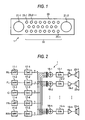
- FIG.1 is a view showing an external appearance (front) of the array speaker device 1.
- an array speaker 22 is arranged in a center portion of an enclosure 20 of the array speaker device 1.
- the array speaker 22 is composed of speaker units 23-1, 23-2, ... 23-n.
- a woofer 21-1 is provided on the left side when viewed from the front and a woofer 21-2 is provided on the right side (referred generically to as woofers 21 hereinafter when it is not needed to distinguish them mutually).
- the array speaker device 1 processes the sound in a high- frequency band (high-frequency component) and the sound in a low-frequency band (low-frequency component) separately, and outputs them from the array speaker 22 and the woofers 21 respectively. Therefore, configurations concerning the processes of the high-frequency component and the low-frequency component will be explained respectively hereunder.
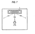
- the signals on five channels (RL, FL, C, FR, and RR) are reproduced as the low-frequency left signal L, the low-frequency right signal R, and the center signal C by the LPFs 31-1 to 31-5 and the adding portions 32-1 and 32-2. Then, these signals are reproduced as the uncorrelated signals Lm and Rm and the correlated signal Cm by the signal separating circuit 33.
Landscapes
- Physics & Mathematics (AREA)
- Engineering & Computer Science (AREA)
- Acoustics & Sound (AREA)
- Signal Processing (AREA)
- Stereophonic System (AREA)
- Circuit For Audible Band Transducer (AREA)
Claims (7)
- Eine Klangsignalausgabevorrichtung (1), wobei die Vorrichtung Folgendes aufweist:einen Empfangsabschnitt zum Empfangen von Signalen auf einer Vielzahl von Kanälen (RL, FL, C, FR, RR);einen Bandaufteilungsabschnitt (11-1, 11-2, 11-3, 11-4, 11-5; 31-1, 31-2, 31-3, 31-4, 31-5) zum Aufspalten des Signals auf der Vielzahl von Kanälen (RL, FL, C, FR, RR), zum jeweiligen Erzeugen von Niederfrequenzsignalen, deren Frequenz niedriger ist als eine vorbestimmte Frequenz;einen Trennungsabschnitt (33) zum Trennen einer korrelierten Komponente (Cm) und unkorrelierter Komponenten (Lm, Rm) zwischen vorbestimmten Kanälen (L, C, R) von den Niederfrequenzsignalen auf der Vielzahl von Kanälen (RL, FL, C, FR, RR);einen korrelierte-Komponenten-Ausgabeabschnitt (34-3; 35-1, 35-2, 36-1, 36-2, 21-1, 21-2) zum Aufprägen einer zweiten Richtungscharakteristik auf die korrelierten Komponenten (Cm) der Signale auf den entsprechenden Kanälen (L, C, R), zum Ausgeben einer aufgeprägten Komponente, deren Klangbild in der Frontrichtung lokalisiert ist;
gekennzeichnet durcheinen unkorrelierte-Komponenten-Ausgabeabschnitt (34-1; 34-2, 35-1, 35-2, 36-1, 36-2, 21-1, 21-2) zum Aufprägen einer ersten Richtungscharakteristik auf die unkorrelierten Komponenten (Lm, Rm) der Signale auf den entsprechenden Kanälen (L, C, R), zum Ausgeben von aufgeprägten Komponenten mit einem Richtungscharakteristik-Zentrum, gerichtet in eine Rechtsrichtung oder eine Linksrichtung bezüglich einer Frontrichtung. - Die Klangsignalausgabevorrichtung nach Anspruch 1, wobei die Vorrichtung ferner Folgendes aufweist:einen instantanen Klangpegelmessabschnitt (331-1, 331-2) zum Messen von instantanen Schalldrücken von Niederfrequenzsignalen auf den vorbestimmten Kanälen (L, C, R),wobei der Trennungsabschnitt (33) konfiguriert ist, zum Trennen der korrelierten Komponenten (Cm) und der unkorrelierten Komponenten (Lm, Rm) von den Niederfrequenzsignalen auf der Vielzahl von Kanälen (RL, FL, C, FR, RR), basierend auf den instantanen Schalldrücken.
- Die Klangsignalausgabevorrichtung nach Anspruch 1, wobei die Vorrichtung ferner Folgendes aufweist:einen Filterabschnitt (52-1, 52-2) zum Verarbeiten vorbestimmter Signale, die in den Niederfrequenzsignalen auf der Vielzahl von Kanälen (RL, FL, C, FR, RR) enthalten sind, durch die Anwendung adaptiver Filter, wobei die adaptiven Filter die Niederfrequenzsignale auf einer anderen Vielzahl von Kanälen als ein entsprechendes Zielsignal verwendet, um ein simuliertes Signal zu erzeugen,wobei der Trennungsabschnitt (33) konfiguriert ist, zum Trennen der korrelierten Komponenten (Cm) und der unkorrelierten Komponenten (Lm, Rm), basierend auf dem simulierten Signal.
- Die Klangsignalausgabevorrichtung nach Anspruch 1, wobei der Bandaufteilungsabschnitt (11-1, 11-2, 11-3, 11-4, 11-5; 31-1, 31-2, 31-3, 31-4, 31-5) konfiguriert ist, zum Aufteilen der Signale auf der Vielzahl von Kanälen (RL, FL, C, FR, RR), die von dem Empfangsabschnitt empfangen wurden, um jeweilige Hochfrequenzsignale zu erzeugen, deren Frequenzen höher sind als eine vorbestimmte Frequenz, und wobei
die Klangsignalausgabevorrichtung (1) ferner Folgendes aufweist:einen Hochfrequenz-Surroundausgabeabschnitt (17-1, 17-2, 17-3, 17-4, 17-5; 18-1, 18-2, ... , 18-n; 12-1, 12-2, ... , 12-n; 19-1, 19-2, ... , 19-n; 22, 23-1, 23-2, ... 23-n), zum Ausgeben der Hochfrequenzsignale auf der Vielzahl von Kanälen (RL, FL, C, FR, RR) als eine Surround-Klang Wiedergabe. - Die Klangsignalausgabevorrichtung nach Anspruch 4, wobei der unkorrelierte-Komponenten-Ausgabeabschnitt und der korrelierte-Komponenten-Ausgabeabschnitt eine Vielzahl von Niederfrequenz-Wiedergabetieftöner (21-1, 21-2) ist; und wobei der Hochfrequenz-Surroundausgabeabschnitt ein Array-Lautsprecher (22) mit einer Vielzahl von Lautsprechereinheiten (23-1, 23-2, ... , 23-n) ist.
- Ein Klangsignalausgabeverfahren, wobei das Verfahren die folgenden Schritte aufweist:Empfangen von Signalen auf einer Vielzahl von Kanälen (RL, FL, C, FR, RR);Aufspalten des Signals auf der Vielzahl von Kanälen, zum jeweiligen Erzeugen von Niederfrequenzsignalen, deren Frequenz niedriger ist als eine vorbestimmte Frequenz;Trennen einer korrelierten Komponente (Cm) und unkorrelierter Komponenten (Lm, Rm) zwischen vorbestimmten Kanälen (L, C, R) von den Niederfrequenzsignalen auf der Vielzahl von Kanälen (RL, FL, C, FR, RR);Aufprägen einer ersten Richtungscharakteristik auf die unkorrelierten Komponenten (Lm, Rm) der Signale auf den entsprechenden Kanälen (L, C, R), zum Ausgeben von aufgeprägten Komponenten mit einem Richtungscharakteristik-Zentrum, gerichtet in eine Rechtsrichtung oder eine Linksrichtung bezüglich einer Frontrichtung;Aufprägen einer zweiten Richtungscharakteristik auf die korrelierten Komponenten (Cm) der Signale auf den entsprechenden Kanälen (L, C, R), zum Ausgeben einer aufgeprägten Komponente.
- Ein computerlesbares Aufnahmemedium mit einem darauf aufgenommenen Programm zum Veranlassen eines Computers zum Ausführen eines Klangsignalausgabeverfahrens gemäß Anspruch 6.
Applications Claiming Priority (1)
| Application Number | Priority Date | Filing Date | Title |
|---|---|---|---|
| JP2008054491A JP4655098B2 (ja) | 2008-03-05 | 2008-03-05 | 音声信号出力装置、音声信号出力方法およびプログラム |
Publications (2)
| Publication Number | Publication Date |
|---|---|
| EP2099238A1 EP2099238A1 (de) | 2009-09-09 |
| EP2099238B1 true EP2099238B1 (de) | 2012-01-25 |
Family
ID=40651752
Family Applications (1)
| Application Number | Title | Priority Date | Filing Date |
|---|---|---|---|
| EP09003228A Ceased EP2099238B1 (de) | 2008-03-05 | 2009-03-05 | Tonsignalausgabevorrichtung, Tonsignalausgabeverfahren und computerlesbares Aufzeichnungsmedium |
Country Status (4)
| Country | Link |
|---|---|
| US (1) | US8189795B2 (de) |
| EP (1) | EP2099238B1 (de) |
| JP (1) | JP4655098B2 (de) |
| CN (1) | CN101527875B (de) |
Families Citing this family (27)
| Publication number | Priority date | Publication date | Assignee | Title |
|---|---|---|---|---|
| JP3915804B2 (ja) * | 2004-08-26 | 2007-05-16 | ヤマハ株式会社 | オーディオ再生装置 |
| US8351629B2 (en) | 2008-02-21 | 2013-01-08 | Robert Preston Parker | Waveguide electroacoustical transducing |
| US8295526B2 (en) | 2008-02-21 | 2012-10-23 | Bose Corporation | Low frequency enclosure for video display devices |
| US8351630B2 (en) | 2008-05-02 | 2013-01-08 | Bose Corporation | Passive directional acoustical radiating |
| US8265310B2 (en) * | 2010-03-03 | 2012-09-11 | Bose Corporation | Multi-element directional acoustic arrays |
| US8139774B2 (en) * | 2010-03-03 | 2012-03-20 | Bose Corporation | Multi-element directional acoustic arrays |
| JP5565044B2 (ja) * | 2010-03-31 | 2014-08-06 | ヤマハ株式会社 | スピーカ装置 |
| US8553894B2 (en) | 2010-08-12 | 2013-10-08 | Bose Corporation | Active and passive directional acoustic radiating |
| JP5417352B2 (ja) * | 2011-01-27 | 2014-02-12 | 株式会社東芝 | 音場制御装置及び方法 |
| CN104136299B (zh) * | 2011-12-29 | 2017-02-15 | 英特尔公司 | 用于在车内对声音进行导向的系统、方法以及装置 |
| JP5776597B2 (ja) * | 2012-03-23 | 2015-09-09 | ヤマハ株式会社 | 音信号処理装置 |
| JP5946090B2 (ja) * | 2012-07-12 | 2016-07-05 | パイオニア株式会社 | 音響信号処理装置及び音響信号処理方法 |
| WO2014034555A1 (ja) * | 2012-08-29 | 2014-03-06 | シャープ株式会社 | 音声信号再生装置、方法、プログラム、及び記録媒体 |
| CN103414988B (zh) * | 2013-05-21 | 2016-11-23 | 杭州联汇科技股份有限公司 | 一种室内扩声录音设备及语音追踪调整方法 |
| KR20150025852A (ko) * | 2013-08-30 | 2015-03-11 | 한국전자통신연구원 | 멀티채널 오디오 분리 장치 및 방법 |
| US9549260B2 (en) | 2013-12-30 | 2017-01-17 | Skullcandy, Inc. | Headphones for stereo tactile vibration, and related systems and methods |
| US9451355B1 (en) | 2015-03-31 | 2016-09-20 | Bose Corporation | Directional acoustic device |
| US10057701B2 (en) | 2015-03-31 | 2018-08-21 | Bose Corporation | Method of manufacturing a loudspeaker |
| CN106067996B (zh) * | 2015-04-24 | 2019-09-17 | 松下知识产权经营株式会社 | 语音再现方法、语音对话装置 |
| EP3089476A1 (de) * | 2015-04-27 | 2016-11-02 | Fraunhofer-Gesellschaft zur Förderung der angewandten Forschung e.V. | Soundsystem |
| CN107925814B (zh) * | 2015-10-14 | 2020-11-06 | 华为技术有限公司 | 生成提升声音印象的方法和设备 |
| WO2017127271A1 (en) * | 2016-01-18 | 2017-07-27 | Boomcloud 360, Inc. | Subband spatial and crosstalk cancellation for audio reproduction |
| US10225657B2 (en) | 2016-01-18 | 2019-03-05 | Boomcloud 360, Inc. | Subband spatial and crosstalk cancellation for audio reproduction |
| US9668081B1 (en) * | 2016-03-23 | 2017-05-30 | Htc Corporation | Frequency response compensation method, electronic device, and computer readable medium using the same |
| WO2018229821A1 (ja) | 2017-06-12 | 2018-12-20 | ヤマハ株式会社 | 信号処理装置、遠隔会議装置、および信号処理方法 |
| US10764704B2 (en) | 2018-03-22 | 2020-09-01 | Boomcloud 360, Inc. | Multi-channel subband spatial processing for loudspeakers |
| US10841728B1 (en) | 2019-10-10 | 2020-11-17 | Boomcloud 360, Inc. | Multi-channel crosstalk processing |
Family Cites Families (13)
| Publication number | Priority date | Publication date | Assignee | Title |
|---|---|---|---|---|
| EP0608937B1 (de) | 1993-01-27 | 2000-04-12 | Koninklijke Philips Electronics N.V. | Tonsignalverarbeitungsanordnung zur Ableitung eines Mittelkanalsignals und audiovisuelles Wiedergabesystem mit solcher Verarbeitungsanordnung |
| JP3509135B2 (ja) * | 1993-08-20 | 2004-03-22 | 三菱電機株式会社 | 音響再生装置 |
| US5771295A (en) * | 1995-12-26 | 1998-06-23 | Rocktron Corporation | 5-2-5 matrix system |
| EP0988773A4 (de) * | 1997-05-28 | 2006-01-11 | Jerald L Bauck | Lautsprecheranordnung zur vergrösserung des idealen punktes |
| WO2000024226A1 (en) * | 1998-10-19 | 2000-04-27 | Onkyo Corporation | Surround-sound system |
| KR20040068194A (ko) | 2001-12-05 | 2004-07-30 | 코닌클리케 필립스 일렉트로닉스 엔.브이. | 스테레오 신호를 강화하기 위한 회로 및 방법 |
| GB0304126D0 (en) * | 2003-02-24 | 2003-03-26 | 1 Ltd | Sound beam loudspeaker system |
| JP4254502B2 (ja) | 2003-11-21 | 2009-04-15 | ヤマハ株式会社 | アレースピーカ装置 |
| EP1815716A4 (de) | 2004-11-26 | 2011-08-17 | Samsung Electronics Co Ltd | Vorrichtung und verfahren zur verarbeitung von mehrkanal-audioeingangssignalen zur erzeugung von mindestens zwei kanalausgangssignalen daraus sowie computerlesbares medium mit ausführbarem code zur durchführung dieses verfahrens |
| JP4779381B2 (ja) | 2005-02-25 | 2011-09-28 | ヤマハ株式会社 | アレースピーカ装置 |
| KR100717066B1 (ko) | 2006-06-08 | 2007-05-10 | 삼성전자주식회사 | 심리 음향 모델을 이용한 프론트 서라운드 사운드 재생시스템 및 그 방법 |
| JP4841324B2 (ja) * | 2006-06-14 | 2011-12-21 | アルパイン株式会社 | サラウンド生成装置 |
| JP2008054491A (ja) | 2006-07-28 | 2008-03-06 | Nidec Sankyo Corp | モータ |
-
2008
- 2008-03-05 JP JP2008054491A patent/JP4655098B2/ja not_active Expired - Fee Related
-
2009
- 2009-03-04 US US12/397,858 patent/US8189795B2/en not_active Expired - Fee Related
- 2009-03-05 EP EP09003228A patent/EP2099238B1/de not_active Ceased
- 2009-03-05 CN CN2009101272036A patent/CN101527875B/zh not_active Expired - Fee Related
Also Published As
| Publication number | Publication date |
|---|---|
| EP2099238A1 (de) | 2009-09-09 |
| JP2009212890A (ja) | 2009-09-17 |
| JP4655098B2 (ja) | 2011-03-23 |
| CN101527875B (zh) | 2011-12-28 |
| US20090225992A1 (en) | 2009-09-10 |
| US8189795B2 (en) | 2012-05-29 |
| CN101527875A (zh) | 2009-09-09 |
Similar Documents
| Publication | Publication Date | Title |
|---|---|---|
| EP2099238B1 (de) | Tonsignalausgabevorrichtung, Tonsignalausgabeverfahren und computerlesbares Aufzeichnungsmedium | |
| US8477951B2 (en) | Front surround system and method of reproducing sound using psychoacoustic models | |
| EP0553832B1 (de) | Schallfeldsteuerungssystem | |
| JP4732807B2 (ja) | オーディオ信号処理 | |
| US8442237B2 (en) | Apparatus and method of reproducing virtual sound of two channels | |
| KR100626233B1 (ko) | 스테레오 확장 네트워크에서의 출력의 등화 | |
| US8345892B2 (en) | Front surround sound reproduction system using beam forming speaker array and surround sound reproduction method thereof | |
| KR102346935B1 (ko) | 매칭되지 않은 트랜스오럴 라우드스피커 시스템용 강화된 가상 스테레오 재생 | |
| KR101567461B1 (ko) | 다채널 사운드 신호 생성 장치 | |
| KR101368859B1 (ko) | 개인 청각 특성을 고려한 2채널 입체 음향 재생 방법 및장치 | |
| US8027476B2 (en) | Sound reproduction apparatus and sound reproduction method | |
| KR100608025B1 (ko) | 2채널 헤드폰용 입체 음향 생성 방법 및 장치 | |
| WO2012042905A1 (ja) | 音響再生装置および音響再生方法 | |
| EP1260119B1 (de) | Multikanaltonwiedergabesystem für stereophonische signale | |
| KR20020059725A (ko) | 입력 오디오 스테레오신호를 처리하기 위한 2개의 방법 및2개의 장치와, 오디오 스테레오신호 재생시스템 | |
| JPH06269098A (ja) | 音場制御システム | |
| JP2001314000A (ja) | 音場生成システム | |
| KR101745019B1 (ko) | 오디오 시스템 및 그 제어방법 | |
| JP2002262385A (ja) | 音像定位信号の生成方法、及び音像定位信号生成装置 | |
| JPH08205297A (ja) | サラウンド信号処理装置 | |
| JP4357218B2 (ja) | ヘッドホン再生方法及び装置 | |
| JP3925633B2 (ja) | 音声再生装置 | |
| JP2017175417A (ja) | 音響再生装置 | |
| JP2006042316A (ja) | 音像上方拡大回路 |
Legal Events
| Date | Code | Title | Description |
|---|---|---|---|
| PUAI | Public reference made under article 153(3) epc to a published international application that has entered the european phase |
Free format text: ORIGINAL CODE: 0009012 |
|
| AK | Designated contracting states |
Kind code of ref document: A1 Designated state(s): AT BE BG CH CY CZ DE DK EE ES FI FR GB GR HR HU IE IS IT LI LT LU LV MC MK MT NL NO PL PT RO SE SI SK TR |
|
| AX | Request for extension of the european patent |
Extension state: AL BA RS |
|
| 17P | Request for examination filed |
Effective date: 20100309 |
|
| 17Q | First examination report despatched |
Effective date: 20100409 |
|
| AKX | Designation fees paid |
Designated state(s): DE FR GB |
|
| GRAP | Despatch of communication of intention to grant a patent |
Free format text: ORIGINAL CODE: EPIDOSNIGR1 |
|
| GRAS | Grant fee paid |
Free format text: ORIGINAL CODE: EPIDOSNIGR3 |
|
| GRAA | (expected) grant |
Free format text: ORIGINAL CODE: 0009210 |
|
| AK | Designated contracting states |
Kind code of ref document: B1 Designated state(s): DE FR GB |
|
| REG | Reference to a national code |
Ref country code: GB Ref legal event code: FG4D |
|
| REG | Reference to a national code |
Ref country code: DE Ref legal event code: R096 Ref document number: 602009004839 Country of ref document: DE Effective date: 20120322 |
|
| PLBE | No opposition filed within time limit |
Free format text: ORIGINAL CODE: 0009261 |
|
| STAA | Information on the status of an ep patent application or granted ep patent |
Free format text: STATUS: NO OPPOSITION FILED WITHIN TIME LIMIT |
|
| 26N | No opposition filed |
Effective date: 20121026 |
|
| REG | Reference to a national code |
Ref country code: DE Ref legal event code: R097 Ref document number: 602009004839 Country of ref document: DE Effective date: 20121026 |
|
| REG | Reference to a national code |
Ref country code: FR Ref legal event code: PLFP Year of fee payment: 8 |
|
| REG | Reference to a national code |
Ref country code: FR Ref legal event code: PLFP Year of fee payment: 9 |
|
| REG | Reference to a national code |
Ref country code: FR Ref legal event code: PLFP Year of fee payment: 10 |
|
| PGFP | Annual fee paid to national office [announced via postgrant information from national office to epo] |
Ref country code: GB Payment date: 20180228 Year of fee payment: 10 |
|
| PGFP | Annual fee paid to national office [announced via postgrant information from national office to epo] |
Ref country code: FR Payment date: 20180223 Year of fee payment: 10 |
|
| GBPC | Gb: european patent ceased through non-payment of renewal fee |
Effective date: 20190305 |
|
| PG25 | Lapsed in a contracting state [announced via postgrant information from national office to epo] |
Ref country code: GB Free format text: LAPSE BECAUSE OF NON-PAYMENT OF DUE FEES Effective date: 20190305 |
|
| PG25 | Lapsed in a contracting state [announced via postgrant information from national office to epo] |
Ref country code: FR Free format text: LAPSE BECAUSE OF NON-PAYMENT OF DUE FEES Effective date: 20190331 |
|
| PGFP | Annual fee paid to national office [announced via postgrant information from national office to epo] |
Ref country code: DE Payment date: 20220620 Year of fee payment: 15 |
|
| REG | Reference to a national code |
Ref country code: DE Ref legal event code: R119 Ref document number: 602009004839 Country of ref document: DE |
|
| PG25 | Lapsed in a contracting state [announced via postgrant information from national office to epo] |
Ref country code: DE Free format text: LAPSE BECAUSE OF NON-PAYMENT OF DUE FEES Effective date: 20241001 |
|
| PG25 | Lapsed in a contracting state [announced via postgrant information from national office to epo] |
Ref country code: DE Free format text: LAPSE BECAUSE OF NON-PAYMENT OF DUE FEES Effective date: 20241001 |