EP2099351B1 - Racloir de lame présentant un élément de guidage pour délimiter le mouvement de découpage - Google Patents
Racloir de lame présentant un élément de guidage pour délimiter le mouvement de découpage Download PDFInfo
- Publication number
- EP2099351B1 EP2099351B1 EP07817562.7A EP07817562A EP2099351B1 EP 2099351 B1 EP2099351 B1 EP 2099351B1 EP 07817562 A EP07817562 A EP 07817562A EP 2099351 B1 EP2099351 B1 EP 2099351B1
- Authority
- EP
- European Patent Office
- Prior art keywords
- blade
- cutting
- cutting direction
- working
- guide
- Prior art date
- Legal status (The legal status is an assumption and is not a legal conclusion. Google has not performed a legal analysis and makes no representation as to the accuracy of the status listed.)
- Not-in-force
Links
- 238000005520 cutting process Methods 0.000 title claims description 165
- 238000005096 rolling process Methods 0.000 claims description 33
- 239000000758 substrate Substances 0.000 claims description 19
- 239000000463 material Substances 0.000 claims description 17
- 238000000034 method Methods 0.000 claims description 3
- 230000001154 acute effect Effects 0.000 claims description 2
- 238000010276 construction Methods 0.000 claims 1
- 239000006228 supernatant Substances 0.000 description 5
- 239000002131 composite material Substances 0.000 description 4
- 239000005340 laminated glass Substances 0.000 description 3
- 238000005452 bending Methods 0.000 description 2
- 238000013461 design Methods 0.000 description 2
- 238000011161 development Methods 0.000 description 2
- 238000009499 grossing Methods 0.000 description 2
- 238000009434 installation Methods 0.000 description 2
- 239000002184 metal Substances 0.000 description 2
- 229910052751 metal Inorganic materials 0.000 description 2
- 230000001681 protective effect Effects 0.000 description 2
- 238000003860 storage Methods 0.000 description 2
- 241001272720 Medialuna californiensis Species 0.000 description 1
- 230000004308 accommodation Effects 0.000 description 1
- 238000004026 adhesive bonding Methods 0.000 description 1
- 238000006073 displacement reaction Methods 0.000 description 1
- 238000009826 distribution Methods 0.000 description 1
- 238000009408 flooring Methods 0.000 description 1
- 239000011521 glass Substances 0.000 description 1
- 238000002347 injection Methods 0.000 description 1
- 239000007924 injection Substances 0.000 description 1
- 238000003780 insertion Methods 0.000 description 1
- 230000037431 insertion Effects 0.000 description 1
- 238000005304 joining Methods 0.000 description 1
- 238000004519 manufacturing process Methods 0.000 description 1
- 238000003825 pressing Methods 0.000 description 1
- 210000004243 sweat Anatomy 0.000 description 1
- 238000012549 training Methods 0.000 description 1
- 238000009966 trimming Methods 0.000 description 1
- 238000003466 welding Methods 0.000 description 1
- 239000002023 wood Substances 0.000 description 1
Images



Classifications
-
- A—HUMAN NECESSITIES
- A47—FURNITURE; DOMESTIC ARTICLES OR APPLIANCES; COFFEE MILLS; SPICE MILLS; SUCTION CLEANERS IN GENERAL
- A47L—DOMESTIC WASHING OR CLEANING; SUCTION CLEANERS IN GENERAL
- A47L13/00—Implements for cleaning floors, carpets, furniture, walls, or wall coverings
- A47L13/02—Scraping
- A47L13/08—Scraping with scraping blades
Definitions
- the invention relates to a blade scraper with a blade head comprising a blade receptacle with a receiving space for a blade for cutting a material to be cut in a cutting direction, the blade receptacle having a working side from which the blade is in a working position with an operative cutting edge from the blade receptacle protrudes, wherein the blade scraper has a guide for limiting a cutting movement or cutting area of the blade scraper and / or for employment of the blade head in an angle of attack or Anstellwinkel Scheme and wherein the guide is connected to the blade scraper.
- the working edge of the blade in the blade holder runs parallel to the working side.
- a blade scraper for example, in the document DE 199 49 074 A1 and in the DE 101 51 503 A1 disclosed.
- a blade scraper generally requires a particularly sharp blade.
- the blade scraper according to the DE 199 49 074 A1 a blade receptacle with a holding part, which defines the blade in the working position and in a protective position completely covers the same.
- the blade holder in the DE 101 51 503 A1 provided with an upper part which releases the used working edge of a blade in the blade holder in the working position and completely covers the same in the protective position from an upper side.
- a blade scraper In the GB 2 277 900 A a blade scraper is described, the blade is spring-loaded in the insert position and is supported in a rollable manner at a rear end side in the cutting direction.
- the blade scraper is cumbersome to guide two-handed, which complicates a safe working.
- the invention has for its object to provide a blade scraper of the type mentioned, which allows a safer and easier to work.
- the guide (6) has a roll-off device (28) with roll bodies (29) which can be rolled in the cutting direction (s) with running surfaces (30) for supporting and moving the blade scraper (1) on a substrate (U). in and against the cutting direction (s).
- the blade scraper for cutting a substrate by means of rolling elements on the ground is unrolled, wherein the areas or Aufsetzkir the tread with which the rolling bodies each rest on the ground, spanning the Anbenebene.
- a lower feed force for moving the blade scraper is necessary in comparison to slipping, which makes working with the blade scraper invention safer.
- the predetermined rolling direction in the cutting direction of the blade scraper is subjected to a direction dominance in the cutting direction, which is a guide in the cutting direction.
- preferably two rolling bodies in a longitudinal side region in the cutting direction may be spaced from each other and one in the other longitudinal side region and preferably in the cutting direction between the other two rolling bodies can be arranged.
- at least four rolling elements may be provided, wherein in each longitudinal side region a rolling body in the cutting direction leading and a rolling body can be arranged in the cutting direction trailing to the working cutting edge.
- the welds can usually form a supernatant perpendicular to the larger side surface of the floor coverings at their lateral longitudinal edges, which must be cut as smoothly and completely as possible in order to achieve a continuous smooth floor covering surface, without damaging material in the vicinity of the weld.
- a so-called saddle maker's half-moon knife is usually guided along the seams in a free hand, which requires a pronounced skill and skill on the part of the user.
- the guide according to the invention can here also, as further below to limit the cutting area by preventing the blade scraper laterally from or away from the weld during cutting.
- the guide can be designed to keep the blade constant over the weld at an optimal cutting angle, in which the supernatants as smooth as possible and without catching the knife in the sweat to be able to cut off.
- the necessary cutting forces should be reduced, among other things, to be able to intervene in the cutting process more easily correcting and to prevent a rapid fatigue of the user.
- a secure, supported placement of the blade scraper in the cutting area is helpful. It is also possible a side guided support against a laterally upstanding edge, wall, paragraph or the like.
- the guide can be integrally connected to the blade scraper.
- the guide is connected by conventional joining techniques such as screwing, riveting, clipping, gluing with the blade scraper.
- the screwing is preferably given preference with a conventional screw with retractable head, as this is the guide easily replaceable attached to the blade scraper.
- a guide can be easily replaced by another, adapted to the particular application guide or the blade scraper can be used as a conventional blade scraper without a guide.
- a corresponding screwing tool can generally be readily available in a common work area.
- the screwing tool can for example be stored integrated in a handle of the blade scraper.
- the connection of the guide and blade scraper can also be done via a latching means of interlocking or overlapping latching means.
- the guide can for example limit the cutting area in the cutting direction.
- the guide is designed to limit the cutting area perpendicular to the cutting direction or in the longitudinal direction of the working side. This is to avoid that the blade scraper in use does not laterally out of a certain path, such as the above-mentioned weld in the cutting direction.
- the guide a stop device with each have at least one lateral stop on both longitudinal sides of the receptacle, wherein the stops protrude in the longitudinal direction of the blade scraper on the working edge addition.
- the stops can project in or parallel to a blade plane of the blade in working position or perpendicular to the working cutting edge and in the longitudinal direction of the working cutting edge.
- the stops can also protrude laterally in the longitudinal direction of the working side to protect lateral end portions of the cutting edges, the cutting corners.
- this has a flat guide plate with stop projections as stops which laterally delimit a U-shaped incision, wherein the incision in installation position of the guide plate in the blade scraper counter to the cutting direction at least approximately or exactly to the working side or beyond goes.
- the guide plate can advantageously be connected to a larger side surface of the blade head, which expediently has a correspondingly flat bearing surface for abutment of the guide plate.
- Such a contact surface is, for example, in the blade scraper according to the DE 199 49 074 A1 given in the working position lower side of the blade head in the holding position of the support parts, which is formed without projections in the holding position, ie no projecting beyond the underside guide projections, and against which the guide plate is preferably screwed.
- the guide plate is adapted to the profile or outline of the contact surface so that it can not interfere with working with the blade scraper.
- the stop projections may protrude quasi horn-like on the guide plate in plate plane.
- the blade scraper can, like the blade scraper according to the DE 10 2005 059 016 , be formed with support members for supporting the blade in the working position, wherein the support members for holding the blade relative to each other in a holding position are movable and the support members via a hinge connected to each other.
- two support members, a lower and an upper support member is provided, wherein the lower support member, as in the DE 10 2005 059 016 described in more detail, may have a pivoting opening through which the upper support member is pivotable with a rear section in the cutting direction. It is hereby expressly to the DE 10 2005 059 016 referred and whose Offenbahrungsgehalt included in this application.
- a guide arranged above and / or below the blade head has a through-opening which is arranged in alignment with the pivoting opening and by means of which the upper holding part can be pivoted with a section.
- the pivoting opening and the pivoting opening preferably have the same profile or the same outline.
- the stop device bez. the stops may cause the working edge in its lateral end regions, i. in their corners or corners, from above and / or from below and / or laterally cover. This is understood below the page of the blade scraper, which is turned into working position to the cutting material, while the top is the side facing away from the blade scraper understood.
- the working side can, as usual, run perpendicular to the cutting direction, with the working edge of an inserted blade running parallel to the working side. But it can also be used in the recording trapezoidal blades, so that the working edge is oblique to the working side.
- the working side can also run obliquely to the cutting direction and the blade are inserted into the receptacle so that their working edge is parallel to the working side. With the direction of the cutting edge oblique to the cutting edge cutting material can be easily cut off.
- the guide and in particular the above described guide plate arranged on the underside of the blade scraper is preferably screwed to the underside or with the contact surface of the blade head, wherein the screw heads are preferably recessed.
- the guide may have a setting device for adjusting the blade head in an angle of attack or angle of attack.
- the blade can be kept in a certain angle to Schneidgut or to the ground, which solves the task alone completely.
- the blade receptacle can have a larger side surface embodied as a contact surface for engaging a larger side surface of the blade.
- the abutment surface can be arranged in an opening angle which opens in the cutting direction to an underside abutment surface for setting or abutment of the blade scraper on a surface of a substrate to be machined.
- the Anstell II can extend in the cutting direction and parallel to the working side.
- the angle of attack is an acute angle.
- the angle of attack can also be blunt, whereby the blade scraper equal to a reamer or the like can be used.
- the adjusting surface may expediently have at least the size of the contact surface and / or be arranged in a region below or obliquely below the blade scraper or the blade head. It can be divided into several individual areas. Thus, a stable support of the blade head can be achieved on the ground.
- the angle of attack is adjustable.
- the angle of attack in angular ranges of 1 ° to 89 °, preferably from 1 ° to 45 ° and more preferably from 1 ° to 30 ° be adjustable.
- the ideal angle of attack depends, among other things, on the cut material itself and its hardness and brittleness as well as on a depth of cut with which the working cutting edge engages in the cut material.
- the angle of attack can be changed by changing the inclination of the positioning surface and / or the contact surface become.
- the setting can be made continuously or in steps.
- the adjusting device has at least one downwardly extending extension, preferably a downwardly extending guide projection, which has on its in working position downwardly facing end side of the Anstell II.
- the position of the working cutting edge in the working position of the blade scraper with respect to the surface of the cut material can be fixed or changed.
- the longitudinal extension of the guide projection s downwards beyond a projection of the blade described above the Anstell
- both lateral guide projections are aligned parallel to each other.
- a movement alignment in the cutting direction which is equivalent to a guide in the cutting direction and is a guide in the sliding direction.
- the guide projections are arranged in alignment perpendicular to the cutting direction, whereby a cutting direction dominance is enhanced.
- the guide projections may be laterally attached to the blade head or connect to the same in one piece.
- the blade scraper with the runner-like guide projections receives a slide-like shape with the blade head between the runner-like guide projections and a longitudinally extending cutting in the cutting channel into which, for example, the above-described weld is led to its smoothing.
- the guide projections can thus be a support or support for support Make the blade scraper on the working surface. Because of the narrow contact surface, only slight frictional forces between the base and the abutment surface can occur when sliding the runner-like guide projections.
- the guide projections can serve by means of their associated Anstell Structure as part of the adjusting device.
- the guide projections may be arranged at least with a rear section in the cutting direction leading to the working cutting edge.
- the guide projections in the above-described cutting protrusions of the weld can prevent lateral slipping or slipping perpendicular to the cutting direction by laterally abut with its rear portion against the not yet planed or cut and thus superior or the rest of the flooring superior weld.
- the guide projections can also serve for the lateral limitation of the cutting movement or cutting area by the cutting area is defined by the cutting channel and the guide projections prevent lateral slipping out of the cutting material from the cutting area.
- the composite disk described above can be performed with its narrow side through the cutting channel, wherein the guide projections project past the larger side surfaces of the composite disk and thus can serve as a stop against lateral displacement of the composite disk.
- the guide projections can also serve as a stop in the cutting direction. Furthermore, since they can limit or cover the blade at least partially upwards and / or laterally, they can at the same time serve as blade protection.
- the two lateral guide projections can each be in the form of a guide projection pair with a guide projection leading in the cutting direction and a guide projection projecting in the cutting direction be formed, wherein the working cutting edge is arranged in the cutting direction between the front guide projection and the rear guide projection.
- the lateral guide projections may each have a running parallel to the working edge, aligned passage opening into which the blade can project into working position with a longitudinal portion of their working cutting edge.
- the blade is arranged in the working position so that the working cutting edge is arranged with its ends or corners in the opening.
- the blade head may have a body with a bottom parallel to the Anstell structure, arranged at an angle to the bottom contact surface and two parallel, perpendicular to the Anstell II and in the cutting direction longitudinal side surfaces for forming the skids or for connection to the runners.
- the body can be made as an injection molded part or milled part.
- the outer surfaces of the blade head in particular its top and longitudinal side surfaces or runners can be designed to handle ergonomically light, manual attack simultaneously as a handle.
- the edges may be rounded and the top, adapted to a palm interior of a user, be curved.
- a necessary introduction of force in the blade scraper facilitating a non-slip surface for example by means of a transverse corrugation and / or be provided by means of a non-slip surface.
- the rolling bodies can be rotatably mounted on the runners and project in a rolling position with their running surfaces downwards.
- the rolling bodies can generally also be arranged in a waiting position in which they do not project beyond the contact surface on the underside, wherein they are for their use from the waiting position in the running position can be brought and in both positions are preferably fixable or latched.
- the rolling elements can also be arranged on any other components of the blade scraper, such as provided on longitudinal members or directly on a body of the blade head.
- the rolling bodies are designed as rotary cylinders with an axis of rotation perpendicular to the cutting direction.
- a diameter of the rotary cylinder is preferably smaller than a height of the rotary cylinder, whereby the leadership of the blade scraper are reinforced in the cutting direction by the rolling body and an approximately linear support of the blade scraper can be achieved, the power as a result of the distribution of a supporting force over a line also cheaper For example, a more point-like load by means of a ball as a rolling body.
- the guide or the Anstell II projects with its working edge by an amount downwards. Downwards is when cutting to cutting material and / or surface directed towards.
- the blade between a storage position in which the blade does not project beyond the guide or the Anstell Diagram with its working edge by an amount down, and the stowed position movable back and forth and preferably in the ready position and storage position.
- the amount is adjustable. With the amount of the amount at the same time a certain chip thickness to be cut off cutting material can be adjusted.
- recording and / or receiving space for example, via a screw adjustment in the direction of Anstell Diagram and relative to Anstell scenes slidably or, similar to a conventional Handholzhobel be fixed by wedging in a desired position, which allows a continuous adjustment. It can also be a rasterization be provided for the gradual adjustment of the amount.
- the blade which in the stowed position with its working edge overhanging the Anstell II by the amount down, be placed with placement of the Anstell components on a substrate about an axis parallel to the working side and thus reach a working position.
- the blade can be more torsionally rigid and dimensionally stable during a cutting operation and thus make the cutting process safer.
- the same can have two blade receptacles for each blade, wherein the blade used comes in a blade holder with its working edge in the cutting direction and the other serving as a waiting blade blade in the other blade holder with its working cutting preferably opposite to the cutting direction. It may also be provided with a plurality of blade receptacles a carousel, one of which is rotatable in the cutting direction and fixed therein.
- Both blades can be arranged at the same angle of attack.
- the blade used may be mounted at an angle other than that of the waiting blade.
- the angle of attack of the blade used can be greater than that of the waiting blade.
- a fine chip can be cut off in a first cutting of material to be cut with the blade used in the cutting direction and a second cut with returning the blade scraper against the cutting direction with the waiting blade for smoothing the substrate.
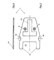
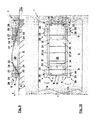
- FIGS. 1 to 10 Three embodiments of a blade scraper 1 with inserted blade K are shown in different views and partial views.
- the blade scraper 1 has a blade head 2 with a blade holder 3.
- the blade holder 3 comprises a receiving space 4 for the blade K for cutting a material to be cut in the FIGS. 5, 6 . 9 and 10 is represented by a subsurface U, in a cutting direction s.
- the blade holder 3 has a rear in the cutting direction s working side 5, from which the blade K in a in the FIGS. 1, 2 . 5, 6 . 9 and 10 shown working position protrudes from the blade holder 3 with a working edge S coming into use.
- the working cutting edge S of the blade K in the blade holder 3 runs parallel to the working side 5
- the blade scraper 1 has a guide 6 for limiting a cutting movement or a cutting area B (see indicated in FIG FIG. 2 and 6 ) of the blade scraper 1 and / or for the employment of the blade head 2 in an angle ß, ß 1 , ß 2 (see Figures 5 and 9 ) on.
- the guide 6 is in the first two embodiments of the blade scraper 1 according to the FIGS. 1 to 8 detachably screwed to the blade head 2, while the guide 6 in the third embodiment of the blade scraper 1 according to the FIGS. 9 and 10 partly in one piece and partially releasably connected by screws with the blade head.
- the blade scraper 1 shown in the first two embodiments is similar to the blade scraper shown in the DE 10 2005 059 016 (not yet published at the time of filing this application), wherein the in the DE 10 2005 059 016 described features, in particular with regard to the design of the blade head 2 are included in the disclosure of this application.
- the blade head 2 of this blade scraper 1 has the underside, ie, as in FIG. 5 shown on its in working position the substrate U side facing a flat connection surface 10 for connecting the guide plate 7 to the blade head 2, wherein the guide plate 7 is connected by means of screw holes 10 of the guide plate 7 sunk arranged screws 8 releasably connected to the blade head 2.
- a handle H is provided.
- the guide plate 7 is arranged parallel to the blades K and the receiving space 4 on the blade head 2.
- the guide plate 7 has two abutment projections 12 as part of a stop device 11 as stops, wherein the abutment projections 12 are arranged in the guide plate plane parallel to the longitudinal axis 1 of the blade scraper 1 in the mounting direction forward and with a larger directional components in the cutting direction s and laterally define a U-shaped incision 13.
- the incision 13 extends in the installation position of the guide plate 7 to just below the working side 5, whereby the blade S of the blade K is exposed in the region of the incision 13.
- the stop projections 12 have around narrow sides 14, which, depending on the use and movement of the blade scraper 1 as stops for limiting the cutting movement or the cutting area B.
- a laminated glass pane (not shown) is trimmed on its narrow sides and its narrow side is guided between the abutment projections 12 such that the abutment projections 12 abut against the larger side surfaces of the laminated glass pane with their inner, mutually facing narrow sides 14 with a lateral running of the blade scraper 1, so that the blade scraper 1 is held on the narrow side of the laminated glass pane.
- the inner narrow sides 14 of the stop projections 12 during trimming of a weld seam of a PVC floor covering, not shown here can serve as stops against a run of the blade scraper 1 perpendicular to the cutting direction s.
- the front side in the cutting direction narrow sides 14 of the stop projections 12 can act as stops against a survey not shown here on the ground U.
- the outer narrow sides 14 of the stop projections can serve as stops against a side elevation, not shown here, on the ground or the like.
- the cutting area is limited, which in the FIG. 2 drawn cutting area B refers to the limitation by the inner narrow sides 14 of the extensions 12.
- the guide plate covers how FIG. 2 Removable, the blade S of the blade K in its edge areas from below from.
- the guide plate 7 is adapted to the stop projections 12 to the profile of the blade head 2, so that the guide plate 7 does not interfere with the handling of the blade scraper 1. Also noteworthy is a T-shaped, designed as a through-opening 15 opening of the guide plate 7, through which an upper support member 16 of the blade holder 3 is pivotable, wherein the pivoting of the upper support member 16 against a lower support member 17 for opening and closing the blade holder 3 in detail in the DE 10 2005 059 016 is described, which is incorporated herein by reference.
- the guide plate 7 two lateral engagement openings 18 are provided for lateral manual engagement in the open blade receptacle 3 for removal or insertion of the blade K, wherein in none of Figures 1,2 . 5 and 6 the blade holder 3 is shown open.
- the guide plate 7 is constructed mirror-symmetrically with its longitudinal axis 1 as a mirror axis, which simplifies their production.
- the guide 6 has a completely different structure than that in the first embodiment and also fulfills other tasks for guiding the blade scraper 1.
- two guide projections one in the cutting direction s front Guide projection 20 and a rear in the cutting direction s guide projection 21, provided which are arranged in alignment in the cutting direction s and thus form a total skid 22.
- the narrow shape of the guide projections 20, 21 and their relative position to each other are clear in the FIGS. 8 a and b seen in a plan view of the same.
- the guide projections 19, 20 are also perpendicular to the cutting direction s arranged in alignment.
- the runners 22 and guide projections 20, 21 have on the underside a Anstell phenomenon 23, with which the guide 6 and the guide 6 of the blade head 2 on the in FIGS. 5 and 6 shown underground U supported.
- the respective Anstell components 23 is correspondingly narrow and elongated in the cutting direction s and thus causes, as in a conventional slide guiding the blade scraper 1 in the cutting direction s.
- the guide projections 20, 21 as the stopper projections 12 of the first embodiment of the blade scraper 1 serve as a stop and thus limit the cutting area in the cutting direction s and perpendicular to the cutting direction s.
- the guide projections 20, 21 with their Anstell Chemistry 23 a certain positioning of the blade scraper 1 on the substrate U, which also determines the relative position of the blade K with its working cutting S.
- the Anstell Chemistry 23 is arranged in a fixed angle ⁇ here to the blade K or to a contact surface 24, against which the blade K rests in the blade holder 3.
- the angle ⁇ is exemplary here 40 °.
- the blade K is, as indicated in the drawing, bent elastically in its working position shown here about a bending axis b parallel to the working side 5, so that their working blade S is arranged in the working position at a shallower angle to Anstell Structure 23 than the contact surface 24 and firmer and defined on the substrate U is applied. Further, a buckling strength of the blade or the working blade S is perpendicular to the cutting direction s increased, so that the working blade S attack in a straight line and can allow a smooth, flat cut. With the blade scraper 1 lifted off, which is not shown here, the blade K is relieved of load and the elastic bend is released, ie the blade K is level again and is in a staging position described above.
- the thickness of a cut chip not shown here and / or the deflection of the blade K is determined.
- the supernatant is not changeable, but it can be modifiable via suitable precautions, such as in a wood planer.
- the guide projections 20, 21 are screwed on the upper side or underside with the blade head 2, for which purpose screw holes 8 are provided on the guide projections 20, 21.
- the upper support member 16 cross-rear guide projection 21 has a recess 25 in which the upper support member 16 is pivotable.
- the blade scraper 1 in the FIGS. 9 and 10 is shown very schematically and only an underlying principle reproducing, the blade scraper 1 has a body 26 with the blade head 2 and two side rails 27.
- the guide 6 has a roll-off device 28 with four rollable in the cutting direction s, here wheel-shaped rolling elements 29 with treads 30 for supporting and moving the blade scraper 1 on the ground U in and against the cutting direction s.
- the running surfaces 30 project beyond the blade scraper 1 on the underside in a rolling position shown here.
- a rolling body 29 in the cutting direction s leading and a rolling body 29 in the cutting direction s lagging to the working side 5 is arranged on each longitudinal member 27, a rolling body 29 in the cutting direction s leading and a rolling body 29 in the cutting direction s lagging to the working side 5 is arranged.
- the rolling elements 29 are respectively as far outside and in or against the cutting direction s rotatably mounted on a longitudinal member 27 so that the trained as a carriage blade scraper 1 can be as wide and stable on the ground U.
- the clearer presentation is in FIG. 9 the shown in the side view, front side member omitted with two rolling bodies.
- the side members 27 are, as not explicitly shown, bolted to the blade head 2.
- this embodiment of the blade scraper 1 with its substantially prismatic body 26 and the simple longitudinal members 27 is particularly easy to produce.
- the blade head 2 has two blade holders, a front blade holder 31 in a marked cutting direction and a blade holder 32 which is located in a different cutting angle ⁇ 1 , ⁇ 2 to the base U or to the setting surface 23 the Anstell Chemistry 23 by Aufsetzat 33 of the rolling body 29 is formed.
- the used blade K is used, the working blade S points in the cutting direction s, while in the front blade holder 31 serving as a waiting blade K 'blade is inserted, the working blade S counter to the cutting direction s.
- Both blades K, K ' are fixed in their respective blade receptacle 31, 32 via a holding device, here indicated by a metal strip 34.
- a holding device here indicated by a metal strip 34.
- both blades K, K ' is provided that they bend with the application of the blade scraper 1 on the substrate U to be processed.
- ß 1 of the rear blade holder first a thicker chip from the substrate U are planed.
- Both blades K, K ' are formed with two cutting edges, the working cutting edge S and a replacement cutting edge S', wherein the replacement cutting edge S 'is arranged in the receiving space 4 in a protected manner.
- the replacement cutting edge S' By turning the blade K, K ', the replacement cutting edge S' then inserted as a working cutting edge is arranged outwards, while the working cutting edge S is seconded in the receiving space 4.
Landscapes
- Knives (AREA)
- Details Of Cutting Devices (AREA)
- Processing Of Stones Or Stones Resemblance Materials (AREA)
Claims (15)
- Racloir de lame avec une tête de lame (2) comprenant un logement de lame (3) avec un espace de réception (4) pour une lame destinée à couper une matière à couper dans un dispositif de coupure (s), le logement de lame (3) présentant un côté de travail (5) hors duquel la lame (K) dans une position de travail va sortir du logement de lame (3) avec un tranchant de travail (S) entrant en action, le racloir de lame (1) présentant un élément de guidage (6) pour délimiter un mouvement de découpage ou une zone de découpage (B) du racloir de lame (1) et/ou pour mettre en inclinaison la tête de lame (2) dans un angle de travail (β, β1, β2) ou dans une plage d'angles de travail, et l'élément de guidage (6) étant relié avec le racloir de lame (1), caractérisé en ce que l'élément de guidage (6) comporte un dispositif de déroulement (28) avec des corps roulants (29) adaptés à rouler dans le sens de découpage (2) et présentant des surfaces de roulement (30) pour appuyer et déplacer le racloir de lame (1) sur une base (U) dans le sens et opposé au sens de découpage (s).
- Racloir de lame selon la revendication 1, caractérisé en ce que le côté de travail (5) s'étend perpendiculairement ou en biais par rapport au sens de découpage (s).
- Racloir de lame selon la revendication 1 ou 2, caractérisé en ce que l'élément de guidage (6) comporte un dispositif de mise en inclinaison pour mettre en inclinaison la tête de lame (2) dans un angle de travail (β) ou dans une plage d'angles de travail.
- Racloir de lame selon la revendication 3, caractérisé en ce que le logement de lame (3) comporte une face latérale plus grande configurée comme une surface de contact (24) pour le contact d'une face latérale plus grande de la lame (K), que la surface de contact (24) est arrangée dans un angle de travail (β) s'ouvrant vers le sens de découpage (1) par rapport à une surface d'application envers (23), pour mettre ledit racloir de lame (1) en inclinaison sur ou en contact avec une surface à façonner d'une base (U), la surface d'application (23) s'étendant dans le sens de découpage (s) et parallèlement au côté de travail (5), et en ce que l'angle de travail (β) est un angle aigu.
- Racloir de lame selon la revendication 4, caractérisé en ce que l'angle de travail (β) est réglable.
- Racloir de lame selon l'une des revendications 1 à 5, caractérisé en ce qu'il sont prévus au moins quatre corps roulants (29), un corps roulant (29) étant disposé dans chaque zone du côté longitudinal (19) de manière avancée par rapport au tranchant de travail (S) au sens de découpage (s) et un corps roulant (29) étant disposé de manière retardée par rapport au tranchant de travail (S) au sens de découpage (s).
- Racloir de lame selon la revendication 6, caractérisé en ce que les corps roulants (29) sont pivotés à des profilés longitudinaux prévus à un élément tel que les cuves (22) et, dans une position roulante, surpassant celui-ci vers le bas par ses surfaces de roulement (30).
- Racloir selon la revendication 6 ou 7, caractérisé en ce que les corps roulants (19) sont configurés sous forme de cylindre tournant.
- Racloir selon l'une des revendications 1 à 8, comportant la lame disposée dans une position de mise à disposition dans le logement, caractérisé en ce que la lame (K), dans une position de mise à disposition, dépasse ledit élément de guidage (6) vers le bas d'une quantité, par son tranchant de travail (S).
- Racloir de lame selon la revendication (9), caractérisé en ce que ladite quantité est réglable.
- Racloir de lame selon la revendication 9 ou 10, caractérisé en ce que la lame (K), avec la mise de la tête de lame (2) sur une base, peut être amenée dans une position de travail et peut être fléchie autour d'un axe et parallèlement à la face de travail (5).
- Racloir de lame selon l'une des revendications 1 à 11, caractérisé en ce que la tête de lame (2) comporte deux logements de lame (3) pour une lame respective (K, K'), la lame (K) entrant en action étant orientée avec son tranchant de travail (S) dans le sens de découpage (s) dans l'un des logements de lame (3), et l'autre lame (K') qui sert de lame d'attente étant orientée avec son tranchant de travail (S) dans le sens opposé au sens de découpage (s) dans l'autre des logements de lame (3).
- Racloir de lame selon la revendication 12, caractérisé en ce que la tête de lame (2) comporte un logement de lame avant (31) dans le sens de découpage (s) et un logement de lame arrière (32) dans le sens de découpage (s), chacun des logements étant disposés dans un angle de travail différent (β1, β2).
- Racloir de lame selon la revendication 13, caractérisé en ce que la lame (K) entrant en action est logée sous un angle de travail (β1) qui diffère de l'angle de travail (β2) de la lame d'attente (K').
- Procédé pour couper une matière à couper d'une base utilisant un racloir de lame selon l'une des revendications 12 à 14, la tête de lame (2) du racloir de lame comportant deux logements de lame (3) pour une lame respective (K, K'), la lame (K) entrant en action étant orientée avec son tranchant de travail (S) dans le sens de découpage (s) dans l'un des logements de lame (3), et l'autre lame (K') qui sert de lame d'attente étant orientée avec son tranchant de travail (S) dans le sens opposé au sens de découpage (s) dans l'autre des logements de lame (3), le procédé comprenant les étapes suivants:la première découpage d'une limaille grosse de la matière à couper en utilisant la lame (K) entrant en action dans le sens de découpage (s) etla deuxième découpage d'une limaille fine de la matière à couper en retournant le racloir de lame (1) dans le sens opposé au sens de découpage (s) en utilisant la lame de l'attente (K').
Applications Claiming Priority (2)
| Application Number | Priority Date | Filing Date | Title |
|---|---|---|---|
| DE102006046659A DE102006046659B3 (de) | 2006-09-29 | 2006-09-29 | Klingenschaber |
| PCT/DE2007/001720 WO2008040309A1 (fr) | 2006-09-29 | 2007-09-21 | Racloir de lame présentant un élément de guidage pour délimiter le mouvement de découpage |
Publications (2)
| Publication Number | Publication Date |
|---|---|
| EP2099351A1 EP2099351A1 (fr) | 2009-09-16 |
| EP2099351B1 true EP2099351B1 (fr) | 2015-07-01 |
Family
ID=39064294
Family Applications (1)
| Application Number | Title | Priority Date | Filing Date |
|---|---|---|---|
| EP07817562.7A Not-in-force EP2099351B1 (fr) | 2006-09-29 | 2007-09-21 | Racloir de lame présentant un élément de guidage pour délimiter le mouvement de découpage |
Country Status (4)
| Country | Link |
|---|---|
| US (1) | US20090265940A1 (fr) |
| EP (1) | EP2099351B1 (fr) |
| DE (1) | DE102006046659B3 (fr) |
| WO (1) | WO2008040309A1 (fr) |
Families Citing this family (9)
| Publication number | Priority date | Publication date | Assignee | Title |
|---|---|---|---|---|
| DE102008026966A1 (de) * | 2007-12-21 | 2009-06-25 | Mozart Ag | Klingenhalter, insbesondere Fugenhobel, Klinge und Verfahren zum Abziehen und Abhobeln eines Untergrundes |
| TW201114529A (en) * | 2009-10-27 | 2011-05-01 | Goodly Ch Entpr Co Ltd | Scraper |
| US8584403B2 (en) * | 2011-01-03 | 2013-11-19 | Calvin A. Frelier | Fluid flow channel and scavenger system |
| US20140216605A1 (en) * | 2011-04-22 | 2014-08-07 | Stuart Batty | Negative rake scraper |
| USD711206S1 (en) * | 2012-09-07 | 2014-08-19 | Nomis Llc | Trim tool |
| JP6095826B1 (ja) | 2016-04-11 | 2017-03-15 | 株式会社エポック社 | 溶着性ビーズ玩具用スクレイパー |
| JP6108650B1 (ja) * | 2016-08-10 | 2017-04-05 | 株式会社エポック社 | 溶着性ビーズ玩具用スクレイパー |
| US20190202074A1 (en) * | 2018-01-02 | 2019-07-04 | Stanley Black & Decker, Inc. | Knife with Replaceable Blade |
| CN117297441B (zh) * | 2023-10-17 | 2025-07-29 | 珠海格力电器股份有限公司 | 切割机构、滚刷装置及清洁设备 |
Family Cites Families (72)
| Publication number | Priority date | Publication date | Assignee | Title |
|---|---|---|---|---|
| US165356A (en) * | 1875-07-06 | Improvement in dado-planes | ||
| US135341A (en) * | 1873-01-28 | Improvement in planes for scraping | ||
| US586164A (en) * | 1897-07-13 | Floor-plane | ||
| US508273A (en) * | 1893-11-07 | Putty-knife | ||
| US620226A (en) * | 1899-02-28 | Joiner s plane | ||
| US187811A (en) * | 1877-02-27 | Improvement in hand-rubbers | ||
| US558739A (en) * | 1896-04-21 | Stone-dressing tool | ||
| US678776A (en) * | 1900-10-19 | 1901-07-16 | Crist Frank | Chisel-gage. |
| US721178A (en) * | 1902-05-14 | 1903-02-24 | Nels J Johnson | Scraping-tool. |
| US849681A (en) * | 1906-04-23 | 1907-04-09 | William C Lindsay | Putty-remover. |
| US830541A (en) * | 1906-05-26 | 1906-09-11 | Stanley Rule & Level Co | Bench-plane. |
| US864260A (en) * | 1907-03-27 | 1907-08-27 | Grover G Rehfeld | Floor-planer. |
| US879793A (en) * | 1907-05-28 | 1908-02-18 | Andro Nylund | Plane. |
| US923271A (en) * | 1907-09-05 | 1909-06-01 | Charles W Johnson | Floor-scraper. |
| US903868A (en) * | 1908-03-27 | 1908-11-17 | George J Kepplinger | Floor planer and scraper. |
| US1114903A (en) * | 1914-07-29 | 1914-10-27 | David F Moore | Reefing-iron. |
| US1134072A (en) * | 1914-11-05 | 1915-03-30 | Stanley Rule & Level Co | Plane. |
| US1268873A (en) * | 1917-01-15 | 1918-06-11 | Alfred Nelson | Floor-scraper. |
| US1442544A (en) * | 1920-06-21 | 1923-01-16 | Erich Rahardt | Floor-scraping device |
| US1399381A (en) * | 1920-11-08 | 1921-12-06 | Evans Isaac | Spreading device |
| US1387969A (en) * | 1920-12-27 | 1921-08-16 | Elias Otto | Plane |
| US1495393A (en) * | 1921-11-28 | 1924-05-27 | Arthur J Beckett | Floor scraper |
| US1509278A (en) * | 1923-07-19 | 1924-09-23 | Agerup John | Device for coating pulleys with composition |
| US1567342A (en) * | 1924-04-04 | 1925-12-29 | Szako John | Plane |
| US1753103A (en) * | 1928-12-08 | 1930-04-01 | Greenlee Bros & Co | Recessing tool |
| US1828103A (en) * | 1930-03-03 | 1931-10-20 | Carl L Wright | Boat plank fitting method |
| US1877699A (en) * | 1931-03-16 | 1932-09-13 | George E Showers | Attachment for tools |
| US1911179A (en) * | 1931-11-25 | 1933-05-30 | Calleja John | Multiple cutter plane |
| US1979554A (en) * | 1932-06-22 | 1934-11-06 | George W Huntington | Cutting and stripping machine for pavement joints and the like |
| US2264939A (en) * | 1940-04-20 | 1941-12-02 | Hawkins Luty | Dropping board scraper |
| US2241608A (en) * | 1940-08-23 | 1941-05-13 | August J Lurie | Cutting device |
| US2565193A (en) * | 1948-06-07 | 1951-08-21 | Louis P Meconi | Bit clamp for carpenter's plane |
| US2787056A (en) * | 1954-06-22 | 1957-04-02 | Robert E Dobratz | Window paint scraper |
| US3203021A (en) * | 1963-09-20 | 1965-08-31 | Applied Science Lab Inc | Applicator for thin layer chromatography |
| US3237235A (en) * | 1964-01-21 | 1966-03-01 | Moody Willard Bruce | Joint raker |
| US3643328A (en) * | 1969-10-08 | 1972-02-22 | Albert V Wainwright Jr | Ski-renovating tool |
| US3662423A (en) * | 1970-10-09 | 1972-05-16 | Lloyd P Miller | Rock face brick cleaning rake |
| FR2313519A1 (fr) * | 1975-06-03 | 1976-12-31 | Venditti Gaetan | Accessoire pour truelle, taloche ou platoire de macons ou de peintre-platriers |
| US4235268A (en) * | 1979-01-22 | 1980-11-25 | Savary Clarence H | Tool for forming door mortice |
| FR2498101A1 (fr) * | 1981-01-16 | 1982-07-23 | Zaragoza Antoine | Racloir guide |
| GB2125721B (en) * | 1982-07-14 | 1986-02-12 | Keith Lodge | A hand tool |
| US4549351A (en) * | 1982-08-27 | 1985-10-29 | Stanbery Dan P | Coving cutter assembly |
| US4520564A (en) * | 1983-11-07 | 1985-06-04 | Wivinis Gerald P | Tool for removing automotive door panels |
| US4549350A (en) * | 1984-01-18 | 1985-10-29 | Glenn Patillo | Method and tool for removing floor covering |
| US4704795A (en) * | 1985-02-22 | 1987-11-10 | Primich John V | Adjustable scraper |
| US4709478A (en) * | 1986-10-02 | 1987-12-01 | Cortelyou Jr David H | Window paint scraper |
| US4779301A (en) * | 1987-05-04 | 1988-10-25 | Edgar Millette | Scraper |
| AU2075788A (en) * | 1987-07-21 | 1989-02-13 | Jurg Gottfried Staubli | Chisel |
| US4821419A (en) * | 1987-08-28 | 1989-04-18 | Lee Valley Tools Ltd. | Blind nailer |
| GB9309846D0 (en) * | 1993-05-13 | 1993-06-23 | Irwin Leslie P | Hand-held tools |
| US5606763A (en) * | 1996-01-19 | 1997-03-04 | Midwest Rake Co. | Applicator for liquid floor levelers |
| US5715605A (en) * | 1996-04-08 | 1998-02-10 | Nadeau; Jacques | Paper roll slabbing tool |
| US6308370B1 (en) * | 1998-02-02 | 2001-10-30 | Roydon Charles Southby | Adhesive spreader |
| US6105469A (en) * | 1998-08-14 | 2000-08-22 | Gracy; Mark S. | Material removal tool with wedge and fulcrum |
| FR2789618B1 (fr) * | 1999-02-16 | 2001-05-11 | Preposreve Sarl | Couteau d'ebarbage et nettoyage de pare-brise, a cache-lame basculant |
| GB9905852D0 (en) * | 1999-03-16 | 1999-05-05 | Brown Alan | Paint scraper |
| US6205608B1 (en) * | 1999-06-08 | 2001-03-27 | Lee M. Bowen | Deck crevice cleaning tool |
| DE19949074C2 (de) * | 1999-10-12 | 2002-06-06 | Addy Flocke | Klingenschaber |
| US6708412B2 (en) * | 2001-08-22 | 2004-03-23 | Lee Valley Tools, Ltd. | Bench plane jointer fence |
| US6484404B1 (en) * | 2001-10-16 | 2002-11-26 | Liang-Shen Kao | Multi-functional exacting knife structure |
| DE10151503A1 (de) * | 2001-10-18 | 2003-05-08 | Gronbach Forschungs Und Entwic | Klingenschaber |
| US20030131479A1 (en) * | 2002-01-14 | 2003-07-17 | Kinnaman Forest E. | Run cutter |
| US7401861B2 (en) * | 2003-04-23 | 2008-07-22 | Patrick W. Purcell | Apparatus for removing surface coverings and methods for using such apparatus |
| US7437794B2 (en) * | 2003-11-20 | 2008-10-21 | Massaro John S | Magnetic scraper |
| US20050172432A1 (en) * | 2004-02-09 | 2005-08-11 | Sullivan Andrew J. | Tool for cleaning taped seams of dry wall |
| US7185436B2 (en) * | 2004-03-30 | 2007-03-06 | Kyocera Tycom Corporation | Multi-position peeler apparatus |
| US7293361B1 (en) * | 2004-05-07 | 2007-11-13 | Ames True Temper, Inc. | Hand tool for chopping ice |
| US7530173B2 (en) * | 2005-08-29 | 2009-05-12 | Economaki John J | Variable cutting angle hand plane |
| US7930991B2 (en) * | 2005-10-18 | 2011-04-26 | Paul N. Gardner Company Incorporated | Adjustable film applicator |
| DE102005059016B4 (de) * | 2005-12-08 | 2008-04-03 | Mozart Ag | Klingenschaber |
| US7552976B2 (en) * | 2006-01-18 | 2009-06-30 | Brown Methuselah Matt I | Automated roofing material removal machine and method |
| USD595558S1 (en) * | 2008-06-04 | 2009-07-07 | Lee Valley Tools, Ltd. | Skew rabbet plane |
-
2006
- 2006-09-29 DE DE102006046659A patent/DE102006046659B3/de not_active Expired - Fee Related
-
2007
- 2007-09-21 WO PCT/DE2007/001720 patent/WO2008040309A1/fr not_active Ceased
- 2007-09-21 EP EP07817562.7A patent/EP2099351B1/fr not_active Not-in-force
- 2007-09-21 US US12/443,666 patent/US20090265940A1/en not_active Abandoned
Also Published As
| Publication number | Publication date |
|---|---|
| EP2099351A1 (fr) | 2009-09-16 |
| DE102006046659B3 (de) | 2008-06-05 |
| US20090265940A1 (en) | 2009-10-29 |
| WO2008040309A1 (fr) | 2008-04-10 |
Similar Documents
| Publication | Publication Date | Title |
|---|---|---|
| EP2099351B1 (fr) | Racloir de lame présentant un élément de guidage pour délimiter le mouvement de découpage | |
| DE102005057213B3 (de) | Messer | |
| DE102012004037B4 (de) | Arbeitsgerät | |
| EP4234160B1 (fr) | Système de guidage doté d'une machine-outil portative et rails de guidage | |
| DE10054174A1 (de) | Küchengerät zum Schneiden von Schneidgut | |
| EP0525438A1 (fr) | Scie circulaire portative à moteur pour travail manuel | |
| EP2638995B1 (fr) | Machine de coupe portable | |
| EP2638997B1 (fr) | Machine de coupe portable | |
| EP2638996B1 (fr) | Machine de coupe portable | |
| DE112023000461T5 (de) | Schienensäge | |
| DE102012005444A1 (de) | Hand-Werkzeugmaschine | |
| DE3014463A1 (de) | Passepartout-schneidgeraet | |
| DE102008050475B4 (de) | Parallelanschlag | |
| EP2229491B1 (fr) | Porte-lame et son procédé d'utilisation | |
| DE202018102354U1 (de) | Tapetenschneidevorrichtung | |
| DE102006009126B4 (de) | Messer und Kunststoffbearbeitungsmaschine mit einem solchen Messer | |
| DE1300889B (de) | Kohlenhobel mit vor den Werkzeugtraegern angeordneter Einrichtung zur Begrenzung der Schnittiefe | |
| DE19703807C1 (de) | Vorrichtung zum manuellen Schärfen von Schneidkanten von Schneidwerkzeugen | |
| DE20100087U1 (de) | Handkreissäge | |
| DE29601840U1 (de) | Schleifvorrichtung | |
| DE19500237A1 (de) | Vorrichtung zum Schneiden von Bodenbelägen | |
| EP3782754B1 (fr) | Lime destinée à limer la denture de coupe d'une chaîne coupante | |
| DE2519016C2 (de) | Schneidvorrichtung für Tapeten oder andere Papiere | |
| DE20009747U1 (de) | Tischkreissäge | |
| DE202007011242U1 (de) | Führungseinrichtung einer Zapfenschneidemaschine bzw. Zapfenfräsmaschine |
Legal Events
| Date | Code | Title | Description |
|---|---|---|---|
| PUAI | Public reference made under article 153(3) epc to a published international application that has entered the european phase |
Free format text: ORIGINAL CODE: 0009012 |
|
| 17P | Request for examination filed |
Effective date: 20090429 |
|
| AK | Designated contracting states |
Kind code of ref document: A1 Designated state(s): AT BE BG CH CY CZ DE DK EE ES FI FR GB GR HU IE IS IT LI LT LU LV MC MT NL PL PT RO SE SI SK TR |
|
| DAX | Request for extension of the european patent (deleted) | ||
| GRAP | Despatch of communication of intention to grant a patent |
Free format text: ORIGINAL CODE: EPIDOSNIGR1 |
|
| INTG | Intention to grant announced |
Effective date: 20150220 |
|
| GRAS | Grant fee paid |
Free format text: ORIGINAL CODE: EPIDOSNIGR3 |
|
| GRAA | (expected) grant |
Free format text: ORIGINAL CODE: 0009210 |
|
| AK | Designated contracting states |
Kind code of ref document: B1 Designated state(s): AT BE BG CH CY CZ DE DK EE ES FI FR GB GR HU IE IS IT LI LT LU LV MC MT NL PL PT RO SE SI SK TR |
|
| REG | Reference to a national code |
Ref country code: GB Ref legal event code: FG4D Free format text: NOT ENGLISH |
|
| REG | Reference to a national code |
Ref country code: AT Ref legal event code: REF Ref document number: 733437 Country of ref document: AT Kind code of ref document: T Effective date: 20150715 Ref country code: CH Ref legal event code: EP |
|
| REG | Reference to a national code |
Ref country code: IE Ref legal event code: FG4D Free format text: LANGUAGE OF EP DOCUMENT: GERMAN |
|
| REG | Reference to a national code |
Ref country code: DE Ref legal event code: R096 Ref document number: 502007014015 Country of ref document: DE |
|
| REG | Reference to a national code |
Ref country code: FR Ref legal event code: PLFP Year of fee payment: 9 |
|
| REG | Reference to a national code |
Ref country code: NL Ref legal event code: MP Effective date: 20150701 |
|
| REG | Reference to a national code |
Ref country code: LT Ref legal event code: MG4D |
|
| PG25 | Lapsed in a contracting state [announced via postgrant information from national office to epo] |
Ref country code: FI Free format text: LAPSE BECAUSE OF FAILURE TO SUBMIT A TRANSLATION OF THE DESCRIPTION OR TO PAY THE FEE WITHIN THE PRESCRIBED TIME-LIMIT Effective date: 20150701 Ref country code: GR Free format text: LAPSE BECAUSE OF FAILURE TO SUBMIT A TRANSLATION OF THE DESCRIPTION OR TO PAY THE FEE WITHIN THE PRESCRIBED TIME-LIMIT Effective date: 20151002 Ref country code: LV Free format text: LAPSE BECAUSE OF FAILURE TO SUBMIT A TRANSLATION OF THE DESCRIPTION OR TO PAY THE FEE WITHIN THE PRESCRIBED TIME-LIMIT Effective date: 20150701 Ref country code: LT Free format text: LAPSE BECAUSE OF FAILURE TO SUBMIT A TRANSLATION OF THE DESCRIPTION OR TO PAY THE FEE WITHIN THE PRESCRIBED TIME-LIMIT Effective date: 20150701 |
|
| PG25 | Lapsed in a contracting state [announced via postgrant information from national office to epo] |
Ref country code: PL Free format text: LAPSE BECAUSE OF FAILURE TO SUBMIT A TRANSLATION OF THE DESCRIPTION OR TO PAY THE FEE WITHIN THE PRESCRIBED TIME-LIMIT Effective date: 20150701 Ref country code: PT Free format text: LAPSE BECAUSE OF FAILURE TO SUBMIT A TRANSLATION OF THE DESCRIPTION OR TO PAY THE FEE WITHIN THE PRESCRIBED TIME-LIMIT Effective date: 20151102 Ref country code: IS Free format text: LAPSE BECAUSE OF FAILURE TO SUBMIT A TRANSLATION OF THE DESCRIPTION OR TO PAY THE FEE WITHIN THE PRESCRIBED TIME-LIMIT Effective date: 20151101 Ref country code: SE Free format text: LAPSE BECAUSE OF FAILURE TO SUBMIT A TRANSLATION OF THE DESCRIPTION OR TO PAY THE FEE WITHIN THE PRESCRIBED TIME-LIMIT Effective date: 20150701 Ref country code: ES Free format text: LAPSE BECAUSE OF FAILURE TO SUBMIT A TRANSLATION OF THE DESCRIPTION OR TO PAY THE FEE WITHIN THE PRESCRIBED TIME-LIMIT Effective date: 20150701 |
|
| REG | Reference to a national code |
Ref country code: DE Ref legal event code: R097 Ref document number: 502007014015 Country of ref document: DE |
|
| PG25 | Lapsed in a contracting state [announced via postgrant information from national office to epo] |
Ref country code: DK Free format text: LAPSE BECAUSE OF FAILURE TO SUBMIT A TRANSLATION OF THE DESCRIPTION OR TO PAY THE FEE WITHIN THE PRESCRIBED TIME-LIMIT Effective date: 20150701 Ref country code: CZ Free format text: LAPSE BECAUSE OF FAILURE TO SUBMIT A TRANSLATION OF THE DESCRIPTION OR TO PAY THE FEE WITHIN THE PRESCRIBED TIME-LIMIT Effective date: 20150701 Ref country code: IT Free format text: LAPSE BECAUSE OF FAILURE TO SUBMIT A TRANSLATION OF THE DESCRIPTION OR TO PAY THE FEE WITHIN THE PRESCRIBED TIME-LIMIT Effective date: 20150701 Ref country code: LU Free format text: LAPSE BECAUSE OF FAILURE TO SUBMIT A TRANSLATION OF THE DESCRIPTION OR TO PAY THE FEE WITHIN THE PRESCRIBED TIME-LIMIT Effective date: 20150921 Ref country code: EE Free format text: LAPSE BECAUSE OF FAILURE TO SUBMIT A TRANSLATION OF THE DESCRIPTION OR TO PAY THE FEE WITHIN THE PRESCRIBED TIME-LIMIT Effective date: 20150701 Ref country code: MC Free format text: LAPSE BECAUSE OF FAILURE TO SUBMIT A TRANSLATION OF THE DESCRIPTION OR TO PAY THE FEE WITHIN THE PRESCRIBED TIME-LIMIT Effective date: 20150701 Ref country code: SK Free format text: LAPSE BECAUSE OF FAILURE TO SUBMIT A TRANSLATION OF THE DESCRIPTION OR TO PAY THE FEE WITHIN THE PRESCRIBED TIME-LIMIT Effective date: 20150701 |
|
| REG | Reference to a national code |
Ref country code: CH Ref legal event code: PL |
|
| PLBE | No opposition filed within time limit |
Free format text: ORIGINAL CODE: 0009261 |
|
| STAA | Information on the status of an ep patent application or granted ep patent |
Free format text: STATUS: NO OPPOSITION FILED WITHIN TIME LIMIT |
|
| PG25 | Lapsed in a contracting state [announced via postgrant information from national office to epo] |
Ref country code: RO Free format text: LAPSE BECAUSE OF FAILURE TO SUBMIT A TRANSLATION OF THE DESCRIPTION OR TO PAY THE FEE WITHIN THE PRESCRIBED TIME-LIMIT Effective date: 20150701 |
|
| 26N | No opposition filed |
Effective date: 20160404 |
|
| REG | Reference to a national code |
Ref country code: IE Ref legal event code: MM4A |
|
| PG25 | Lapsed in a contracting state [announced via postgrant information from national office to epo] |
Ref country code: CH Free format text: LAPSE BECAUSE OF NON-PAYMENT OF DUE FEES Effective date: 20150930 Ref country code: IE Free format text: LAPSE BECAUSE OF NON-PAYMENT OF DUE FEES Effective date: 20150921 Ref country code: LI Free format text: LAPSE BECAUSE OF NON-PAYMENT OF DUE FEES Effective date: 20150930 |
|
| PG25 | Lapsed in a contracting state [announced via postgrant information from national office to epo] |
Ref country code: SI Free format text: LAPSE BECAUSE OF FAILURE TO SUBMIT A TRANSLATION OF THE DESCRIPTION OR TO PAY THE FEE WITHIN THE PRESCRIBED TIME-LIMIT Effective date: 20150701 |
|
| REG | Reference to a national code |
Ref country code: FR Ref legal event code: PLFP Year of fee payment: 10 |
|
| REG | Reference to a national code |
Ref country code: AT Ref legal event code: MM01 Ref document number: 733437 Country of ref document: AT Kind code of ref document: T Effective date: 20150921 |
|
| PG25 | Lapsed in a contracting state [announced via postgrant information from national office to epo] |
Ref country code: AT Free format text: LAPSE BECAUSE OF NON-PAYMENT OF DUE FEES Effective date: 20150921 |
|
| PG25 | Lapsed in a contracting state [announced via postgrant information from national office to epo] |
Ref country code: MT Free format text: LAPSE BECAUSE OF FAILURE TO SUBMIT A TRANSLATION OF THE DESCRIPTION OR TO PAY THE FEE WITHIN THE PRESCRIBED TIME-LIMIT Effective date: 20150701 |
|
| PG25 | Lapsed in a contracting state [announced via postgrant information from national office to epo] |
Ref country code: HU Free format text: LAPSE BECAUSE OF FAILURE TO SUBMIT A TRANSLATION OF THE DESCRIPTION OR TO PAY THE FEE WITHIN THE PRESCRIBED TIME-LIMIT; INVALID AB INITIO Effective date: 20070921 Ref country code: BG Free format text: LAPSE BECAUSE OF FAILURE TO SUBMIT A TRANSLATION OF THE DESCRIPTION OR TO PAY THE FEE WITHIN THE PRESCRIBED TIME-LIMIT Effective date: 20150701 |
|
| PG25 | Lapsed in a contracting state [announced via postgrant information from national office to epo] |
Ref country code: NL Free format text: LAPSE BECAUSE OF FAILURE TO SUBMIT A TRANSLATION OF THE DESCRIPTION OR TO PAY THE FEE WITHIN THE PRESCRIBED TIME-LIMIT Effective date: 20150701 Ref country code: CY Free format text: LAPSE BECAUSE OF FAILURE TO SUBMIT A TRANSLATION OF THE DESCRIPTION OR TO PAY THE FEE WITHIN THE PRESCRIBED TIME-LIMIT Effective date: 20150701 |
|
| PG25 | Lapsed in a contracting state [announced via postgrant information from national office to epo] |
Ref country code: BE Free format text: LAPSE BECAUSE OF NON-PAYMENT OF DUE FEES Effective date: 20150930 |
|
| PG25 | Lapsed in a contracting state [announced via postgrant information from national office to epo] |
Ref country code: TR Free format text: LAPSE BECAUSE OF FAILURE TO SUBMIT A TRANSLATION OF THE DESCRIPTION OR TO PAY THE FEE WITHIN THE PRESCRIBED TIME-LIMIT Effective date: 20150701 |
|
| REG | Reference to a national code |
Ref country code: FR Ref legal event code: PLFP Year of fee payment: 11 |
|
| REG | Reference to a national code |
Ref country code: FR Ref legal event code: PLFP Year of fee payment: 12 |
|
| PGFP | Annual fee paid to national office [announced via postgrant information from national office to epo] |
Ref country code: FR Payment date: 20180921 Year of fee payment: 12 |
|
| PGFP | Annual fee paid to national office [announced via postgrant information from national office to epo] |
Ref country code: GB Payment date: 20180924 Year of fee payment: 12 |
|
| PGFP | Annual fee paid to national office [announced via postgrant information from national office to epo] |
Ref country code: DE Payment date: 20181126 Year of fee payment: 12 |
|
| REG | Reference to a national code |
Ref country code: DE Ref legal event code: R119 Ref document number: 502007014015 Country of ref document: DE |
|
| PG25 | Lapsed in a contracting state [announced via postgrant information from national office to epo] |
Ref country code: DE Free format text: LAPSE BECAUSE OF NON-PAYMENT OF DUE FEES Effective date: 20200401 |
|
| GBPC | Gb: european patent ceased through non-payment of renewal fee |
Effective date: 20190921 |
|
| PG25 | Lapsed in a contracting state [announced via postgrant information from national office to epo] |
Ref country code: GB Free format text: LAPSE BECAUSE OF NON-PAYMENT OF DUE FEES Effective date: 20190921 Ref country code: FR Free format text: LAPSE BECAUSE OF NON-PAYMENT OF DUE FEES Effective date: 20190930 |