EP2099397B1 - Dispositif d'ouverture des voies aériennes - Google Patents
Dispositif d'ouverture des voies aériennes Download PDFInfo
- Publication number
- EP2099397B1 EP2099397B1 EP07863007.6A EP07863007A EP2099397B1 EP 2099397 B1 EP2099397 B1 EP 2099397B1 EP 07863007 A EP07863007 A EP 07863007A EP 2099397 B1 EP2099397 B1 EP 2099397B1
- Authority
- EP
- European Patent Office
- Prior art keywords
- vessel
- subject
- pump
- neck
- therapeutic apparatus
- Prior art date
- Legal status (The legal status is an assumption and is not a legal conclusion. Google has not performed a legal analysis and makes no representation as to the accuracy of the status listed.)
- Active
Links
Images


Classifications
-
- A—HUMAN NECESSITIES
- A61—MEDICAL OR VETERINARY SCIENCE; HYGIENE
- A61F—FILTERS IMPLANTABLE INTO BLOOD VESSELS; PROSTHESES; DEVICES PROVIDING PATENCY TO, OR PREVENTING COLLAPSING OF, TUBULAR STRUCTURES OF THE BODY, e.g. STENTS; ORTHOPAEDIC, NURSING OR CONTRACEPTIVE DEVICES; FOMENTATION; TREATMENT OR PROTECTION OF EYES OR EARS; BANDAGES, DRESSINGS OR ABSORBENT PADS; FIRST-AID KITS
- A61F5/00—Orthopaedic methods or devices for non-surgical treatment of bones or joints; Nursing devices ; Anti-rape devices
- A61F5/56—Devices for preventing snoring
Definitions
- the present invention relates generally to medical devices. More particularly, the present invention relates to a device for creating and maintaining an obstruction free upper airway.
- US 2006/0266369 A1 discloses devices and methods for maintaining an open airway by application of a force to a patient's tissue in one of inferior, anterior and lateral directions.
- Obstruction of the upper airway can occur at any age.
- Those at risk for having upper airway obstruction include persons with sleep apnea, those with airway tumors or foreign bodies such as aspirated food, and those with inflammatory or traumatic damage to the upper airway, which results in a weakened and collapsible airway wall, a condition known as tracheomalacia.
- hypoxemia a generalized condition of lowered blood oxygen. If left uncorrected, hypoxemia leads to serious end organ injury such as stroke and myocardial infarction (heart attack), and may have a lethal outcome.
- Snoring is a common chronic medical problem that is associated with episodic partial upper airway obstruction during sleep. Snoring afflicts millions of people worldwide. Snoring can lead to chronic fatigue that follows sleep deprivation and is considered by many to be a serious medical problem.
- the sound of snoring is produced by turbulent air-flow moving through an area of partial upper airway obstruction that produces resonant vibrations in the soft tissues adjacent to the upper airway.
- OSA obstructive sleep apnea
- an afflicted individual sustains numerous episodes of apnea, or complete, and often prolonged cessation of breathing. Severe cases may have 100 or more apnea events per hour of sleep.
- OSA results in nocturnal hypoxemia, and leads to cognitive impairment, daytime somnolence, hypertension, increased risk of stroke and myocardial infarction, and insulin resistant diabetes mellitus. Untreated, OSA may result in premature death.
- OSA is caused by closure of the upper airway during sleep due to either alteration in the mechanical properties of the upper airway, and/or to disturbances in neuromuscular control over airway caliber. Alterations in the mechanical properties of the upper airway, which predispose to collapse of the upper airway during sleep, may be caused by anatomical conditions such as large tonsils, or may be idiopathic.
- a variety of medical interventions have been shown to improve the mechanical properties of the upper airway and reduce sleep related airway closure. These include upper airway remodeling surgeries, medical devices that re-position the mandible, and continuous positive airway pressure (CPAP).
- CPAP works by delivering air at pressures above ambient pressure to the upper airway during sleep.
- Application of positive pressure to the upper airway acts as a "stint" and can retard the tendency of the upper airway to collapse during certain stages of sleep in OSA patients.
- the patient In order to deliver higher than ambient pressures to the upper airway, the patient must wear a tight fitting mask covering the mouth and/or nose. This mask is connected to an air supply tube, and a variable pressure air pump.
- An additional component can be added which humidifies the air, to avoid desiccation of the upper airway during treatment.
- There are multiple sources of patient dissatisfaction with CPAP including an uncomfortable face mask which may provoke feelings of claustrophobia, the noise of the air pump and the moisture of the humidification system. Also, some CPAP units are not easily portable and limit patients' ability to travel.
- a device having a vessel is provided.
- the vessel can be a hollow or concave utensil, shaped as a cup, bowl, or the like.
- the vessel has an edge and an internal surface and is configured to fit under the chin of a subject adjacent to the subject's neck at an external location corresponding approximately with the subject's internal soft tissue associated with the neck's anterior triangle.
- the edge may include an adhesive surface.
- a vacuum pump inlet is provided for receiving a negative pressure into the chamber to apply a force to a surface of the neck of the patient to draw the surface into the chamber.
- the device also includes a tube for connecting the vessel to the pressure control device.
- a pressure control device is provided for controlling the applied force within the range of about 4,9 N to 65,5 N (0.5 kilogram to about 6.68 kilograms).
- the applied force is within the range of about 6 N et 60,2 N (0.61 kg to.6.14 kg).
- the applied force is within the range of about 7,25 N to 55,4 N (0.74 kg to 5.65 kg).
- the applied force is within the range of about 8,9 N to 51 N (0.91 kg to 5.2 kg).
- the applied force is within the range of about 10,9 N to 46,9 N (1.11 kg to 4.78 kg).
- the vessel is made of a material having resilient memory such as silicone, urethane or rubber.
- the pressure control device exerts the negative pressure within the interior chamber in the range of about 7,62 Pa to 60,96 Pa (7.62 cm to about 60.96 cm of water).
- a vessel is dimensionally adapted to define an interior chamber for covering the anterior triangle of from about 32.90 cm 2 to about 210.58 cm 2 in surface area.
- the device further includes a dynamic pump.
- the dynamic pump may be a regenerative pump or a centrifugal pump.
- the device includes a positive displacement pump.
- the positive displacement pump may be a vane pump, a diaphragm pump, or a linear pump.
- a method of applying a force to open an upper airway of a patient may be as follows.
- the vessel is placed against a surface of a patient's neck to seat an edge under the chin of the patient to form chamber at a location corresponding approximately with the patient's internal soft tissue associated with the neck's anterior triangle.
- a force in the range of from about 4,9 N to 65,5 N (0.5 kilogram to about 6.68 kilograms) is applied to the interior of the chamber to pull the neck's anterior triangle toward the interior chamber.
- the vessel may be located over the anterior triangle of the patient's neck to treat sleep obstructive sleep apnea and other disorders associated with upper airway obstruction.
- a method of reducing snoring may be as follows.
- the vessel having an opening is placed on the surface of a subject's neck.
- the vessel is configured to fit under the chin of a subject adjacent to the subject's neck at an external location corresponding approximately with the subject's internal soft tissue associated with the neck's anterior triangle.
- the vessel is attached at the opening to a tube having a first end and a second end.
- the first end of the tube is attached at the opening.
- a vacuum source is attached to the second end of the tube.
- the vacuum source has a microprocessor and at least one acoustic sensor connected thereto.
- a force is applied over the anterior triangle of the patient's neck within the range of about 4,9 N to 65,5 N (0.5 kilogram to about 6.68 kilograms).
- a signal corresponding with an acoustic signature of the subject is identified by the acoustic sensor.
- the signal is registered and processed with a microprocessor attached to the vacuum source.
- the level of negative pressure created at the vacuum source is automatically maintained to reduce and/or eliminate snoring.
- the acoustic sensor is a microphone
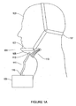
- a device 101 is shown on a subject 103 according to an embodiment of the present invention.
- the device 101 includes a vessel 105, a vacuum source 109, a tube 111, and a pressure control (not shown).
- the vessel 105 includes an edge 107 and an internal surface (not shown).
- the edge 107 seats against the chin and neck of the patient to define a chamber at an external location approximately at the subject's internal soft tissue associated with the neck's anterior triangle.
- a device 101 having a vessel 105 is worn by a subject.
- the vessel 105 is attached to a tube 111 at a first end 113 of the tube 111.
- a second end 115 of the tube 111 is attached to a vacuum source 109.
- the vessel 105 is attached to the subject 103 by a strap 117.
- the vessel 105 may be a hollow or concave utensil.
- the vessel 105 may be shaped as a cup, bowl, or the like.
- the vessel may be formed, molded, or fabricated from any material.
- Non-limiting examples of such materials suitable for constructing the vessel 105 include plastics, metals, natural fabrics, synthetic fabrics, and the like.
- the vessel 105 may also be constructed from a material having resilient memory such as silicone, rubber, or urethane.
- the vessel 105 can be flexible, semi-rigid, or rigid.
- semi-rigid means partially or somewhat rigid.
- Flexible means capable of being bent, usually without breaking, or susceptible of modification or adaptation.
- rigid means stiff or unyielding, not pliant nor flexible.
- the strap 117 functions to attach and helps seal the vessel 105 on the surface of the skin of the subject 103.
- the vessel 105 may be attached to a surface of a subject's neck by a negative pressure exerted by the vacuum source 109.
- adhesive may be utilized to attach the vessel 105 to a surface of the subject's neck.
- the natural anatomical contours of a subject may act in a synergistic manner with any other known means or method of attachment, thereby increasing the effectiveness of the attachment. Further, the natural anatomical contours of the subject may, on its own, act to attach the vessel 105 to the surface of a subject's neck. All would serve as a sufficient means for attaching the vessel 105 on a surface of the subject's neck.
- a seal could be created by, for example, an adhesive, the natural anatomical contours of the subject, or at least one clamp, such as a differential clamp and the like.
- the edge 107 has a high contact pressure area with the skin of the subject's neck. Upon exertion of negative pressure by the vacuum source 109, a seal is created.
- the seal is created by the application of adhesive to the device 101 or the skin of a subject's neck in a desired area.
- the seal may be an elastomeric seal.
- the elastomeric seal may comprise external flaps, extensions or the like, attached to the vessel 105. In one embodiment the elastomeric seal may be attached to the edge 107.
- the elastomeric seal may be made from materials including, but not limited to: Natural Rubber (NR); Polyisoprene (IR); Butyl rubber (copolymer of isobutylene and isoprene, IIR);Halogenated butyl rubbers (Chloro Butyl Rubber: CIIR; Bromo Butyl Rubber: BIIR); Polybutadiene (BR); Styrenebutadiene Rubber (copolymer of polystyrene and polybutadiene, SBR); Nitrile Rubber (copolymer of polybutadiene and acrylonitrile, NBR), also called buna N rubbers; Hydrated Nitrile Rubbers (HNBR) Therban® and Zetpol®; Chloroprene Rubber (CR), polychloroprene, Neoprene, Baypren; EPM (ethylene propylene rubber, a copolymer faeces of polyethylene and polypropylene) and EPDM rubber (ethylene propylene diene rubber
- Figure 1 A illustrates bellows 119 attached to the vessel 105.
- the bellows 119 allow the subject 103 to maintain natural head motion while still allowing the vessel 105 to be effectively sealed against the skin of the subject 103.
- the bellows 119 are formed from the same material as the vessel 105. In alternative embodiments, the bellows 119 may be formed from other suitable materials.
- the bellows 119 have no stiffness in a lateral sense to allow for increased movement of the subject.
- the lateral stiffness of the bellows can vary depending on the lateral movement desired.
- the bellows 119 are rigid enough so that the vessel 105 does not collapse. In some embodiments, the vessel does not have a bellow.
- FIG. 1 B shows an alternative embodiment of the device 101.
- the device 101 includes a vessel 105 and a tube 111.
- the vessel 105 includes an edge 107, which seats against under the chin of the subject to define a chamber at an external location approximately at the internal soft tissue of the subject associated with the anterior triangle of the neck.
- the vessel 105 covers the soft tissue of the subject's anterior triangle of the neck in the range of about 32.9 cm 2 to about 210.58 cm 2 . The range may cover the anatomical variations of the user population.
- the edge 107 helps to seal the vessel 105 on the surface of the skin of the subject and obviates the need for a strap. In this embodiment, the negative pressure exerted by a vacuum source holds the vessel 105 in place.
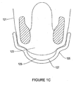
- FIG. 1C shown is an axial view of the device of FIG. 1A on a subject.
- the vessel 105 is placed against the surface of the subject's skin 121 at the subject's mandible 123.
- a vacuum cavity 125 is created between the subject's skin 121 and the vessel's interior surface 127.
- the vacuum cavity 125 allows for the displacement of the soft tissue.
- the vacuum source 109 creates negative pressure which is conveyed through the tube 111 to the vessel 105. Negative pressure means less than atmospheric pressure. This negative pressure, in conjunction with the area bounded by the seal, applies a force and consequently displaces the chin/neck soft tissues forward, thereby enlarging the airway passage in the back of the throat. According to the shown embodiment, the negative pressure created by the vacuum source 109 exerts negative pressure on a surface of the subject's skin.
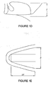
- Figures 1D-1E show a few exemplary dimensions of a subject's mandible. Given the dimensions, the area and the volume of the soft tissue of the subject's mandible is about 32 cm 2 and about 163 cm 3 , respectively. The weight of the mass of the subject's soft tissue is about 0.17 kg. The pressure to counter the weight of the subject's soft tissue is about 7,6 Pa (7.6 cm of water). The maximum effective pressure may depend on the subject's comfort threshold.
- the aggregate force in the range of from about 4,9 N to 65,5 N is applied to the interior of the vessel to pull the neck's anterior triangle toward the interior chamber.
- the aggregate force may preferably be in the range of about 6 N to 60,2 N (0.61 kilograms to about 6.14 kilograms), and more preferably about 7,25 N to 55,4 N (0.74 kilograms to 5.65 kilograms), and more preferably about 8,9 N to 51 N (0.91 kilograms to about 5.2 kilograms), and more preferably from about 10.9 N to 46,9 N (1.11 kilograms to about 4.78 kilograms).
- Figures 1F-1G show CT scans of the subject's upper airway at ambient pressure.
- Figures 1H-1I show the CT scans of the same subject with the negative pressure of 51 centimeters of water vacuum.
- Pressures below about 7,62 Pa (7.62 centimeters of water) vacuum may be ineffective since the pressure may be insufficient to maintain the vessel in the proper anatomic position.
- the pressures applied above about 60,96 Pa (60.96 centimeters of water) vacuum may not be tolerable by a user since speaking and swallowing becomes difficult due to the high pressure.
- the contact pressure applied to the subject's mandible varies depending on the contact area and the operating vacuum level of the vessel.
- a given negative pressure value for example 60 Pa (60 centimeters of water) vacuum
- the skin contact pressure is lowered and may enhance the comfort level for the subject.
- the vacuum source 109 may be any type of pneumatic vacuum pump including a dynamic pump and a positive displacement pump.
- the dynamic pump may be a regenerative pump or a centrifugal pump.
- the positive displacement pump may be a vane pump, a diaphragm pump, or a linear pump.
- the pneumatic vacuum pump may be of any pump that creates a vacuum.
- the pneumatic vacuum pump can provide up to 137 Pa (137 centimeters water) vacuum. Additionally, in an embodiment, the pneumatic vacuum pump can operate at less than 25 dB sound pressure. In a further embodiment, the pneumatic vacuum pump creates no dynamic pressure ripple.
- the pneumatic vacuum pump has a controller for regulating the vacuum level conveyed. Preferably the pneumatic vacuum pump contains all of these features.
- the edge 107 of the vessel 105 may be coated or covered with a means for low pressure skin contact.
- the low pressure skin contact means is an air-tube that traverses the periphery of the vessel. When negative pressure is applied by the vacuum source 109, the low pressure skin contact means will compress slightly.
- the air-tube is inflated with a fixed amount of air. In an alternate embodiment, the air-tube is inflated with the exhaust emitted by the pneumatic vacuum pump.
- the low pressure skin contact means could include without limitation a soft material such foam, rubber, fabric, adhesive, and the like.
- the edge 107 can extend around the full periphery of the vessel 105 including around bellows 119. In alternative embodiments, the edge 107 may not include a means for low pressure contact. The edge 107 may simply be the periphery of the material that comprises the vessel 105 or the vessel 105 and the bellows 119.
- the device 101 may have an auto adjust feature or a controller which would maintain the vacuum level just low enough to eliminate snoring and/or an apnea event.
- the pneumatic vacuum pump would have at least one acoustic sensor that would listen to the acoustic signature emitted of the user coming back up the tube 111.
- the acoustic sensor according to any of the embodiments of the present invention may be any acoustic sensor such as a microphone, or the like.
- the acoustic sensor is in the vessel 105 itself. In alternative embodiments, the acoustic sensor could located anywhere on the device 101. Signal processing would cue a microprocessor to adjust the pressure from the pneumatic vacuum pump to a desired level. The objective is to enhance patient comfort by optimizing the level of negative pressure.
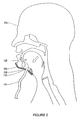
- FIG. 2 shown is a sagittal view of a subject using the device of FIG. 1A .
- the natural anatomical contours of the subject form a seal with the vessel 105.
- the vessel 105 has an opening 129.
- the tube's first end 113 is attached to the vessel 105 at the opening 129.
- negative pressure may be generated at the vacuum source (not shown) and conveyed through the tube 111.
- the negative pressure in the vacuum cavity causes negative pressure to be exerted on the area of skin exposed therein.
- the negative pressure displaces the subject's soft tissue, resulting in an opened stricture or airway. Accordingly, the subject 103 has an airway that is open and free of obstruction.
- a differential clamp 131 is attached to the bellows 119.
- the vessel 105 forms a seal with the subject's neck at a differential clamp-on area 133.
- the differential clamp 131 has a low friction surface 135 that helps form the seal at a differential clamp-on area 135.
- the differential clamp 131 is just one means for low pressure skin contact. In alternative embodiments, it is possible to utilize other clamps similar to differential clamps. Additionally, in alternative embodiments, adhesive may cover the surface of the clamp. As a seal is formed, a low pressure environment is created in the vacuum cavity 125.
- the differential clamp-on area 133 includes both the point at which the differential clamp 131 makes contact with a subject's skin, as well as the area surrounding the point of contact.
- the contact pattern along a subject's neckline becomes shifted downwards rather than being in line with the convolutions of the bellows 119.
- a negative or low pressure exists between the neck and the differential clamp 131 in the vacuum cavity 125, a natural force is carried into the low friction surface 135 against the neck. Accordingly, an additional force is created on the neck that maintains a seal.
- the contact pattern along a subject's neckline is moved such that the natural hydraulic forces, or the difference of the pressures existing in normal atmospheric pressure and the negative or low pressure existing in the vacuum cavity 125 will create an additional load onto the actual seal itself point where the low friction surface 135 makes contact with a subject's neck.
- FIG. 4A shown is a view of a device 137 according to an embodiment of the present invention on a subject.
- the device 137 has a vessel 139.
- the vessel 139 has an edge 141, and an internal surface (not shown).
- the vessel 139 is configured to fit under the chin of a subject 143 adjacent to the subject's neck at an external location corresponding approximately with the subject's internal soft tissue associated with the neck's anterior triangle.
- the vessel 139 is fabricated or formed from a material having a resilient memory. Accordingly, the vessel returns to its original form or position after being bent, compressed, or stretched.
- the vessel 139 can be made of any material having a resilient memory including, but not limited to, plastics, metals, fabrics, polymers, rubbers, and the like.
- An adhesive (not shown) coats at least a portion of the internal surface 147 of the vessel 139 to form a seal against the skin 145 of a subject 143.
- FIG. 4B shown is an axial view of the device of FIG. 4A on a subject.
- the vessel 139 is placed against the surface of the subject's skin 145 at the subject's mandible 147.
- An adhesive coats at least a portion of the internal surface 149 of the vessel 139.
- one process for applying the vessel 139 comprises applying pressure on the exterior surface 151 of the vessel 139 at a point approximately central to vessel 139 causing it to invert.
- the inverted vessel 139 is placed under the chin of the subject 143 adjacent to the subject's neck at an external location corresponding approximately with the subject's internal soft tissue associated with the neck's anterior triangle.
- the pressure applied to the central point of the vessel 139 is removed such that the flexible vessel returns to its original shape thereby taking hold of the skin 145 in contact with the adhesive.
- the skin 145 in contact with the adhesive will be displaced.
- the subject's internal soft tissue is displaced in a forward and downward fashion, thereby enhancing the airway.
- the vessel 139 may be provided without any adhesive on it at all. Accordingly, adhesive could be independently applied to the skin 145 of the subject 143 in a desired area and the vessel 139 could be applied to the coated skin in the manner provided above. In one embodiment, the adhesive could be double sided tape.
- FIG. 5 shown is a sagittal view of a subject using the device of FIG 4A .
- the vessel 139 has an adhesive on at least a portion of its internal surface 149. In contact with the skin, the vessel 139 pulls the subject's skin. The pulling displaces the subject's soft tissue, resulting in an opened stricture. Accordingly, the subject 143 has an airway that is open and free of obstruction.
- the vacuum source 109 has a vacuum pump 153 attached to a motor 155.
- a microcontroller 157 such as a microprocessor, is attached to the motor 155 by a first electrical connection 159.
- a pressure sensor 161 is attached to the microcontroller 157 by a second electrical connection 163.
- a tube 111 connects the vessel (not shown) to the vacuum pump at opposite ends of the tube 111.
- a first pneumatic connection 165 attaches the tube 111 to the pressure sensor 161.
- a relief valve 167 is attached to the tube 111 by a second pneumatic connection 169.
- the vacuum pump 153 may be any type of pneumatic vacuum pump including, but not limited to, a regenerative pump, a vane pump, a diaphragm pump, a centrifugal pump, a positive displacement pump or a dynamic pump.
- the pneumatic vacuum pump can provide up to 137 centimeters water vacuum.
- the microcontroller 157 may be any controller capable of identifying and processing data and/or signals received from the motor 155 and vacuum pump 153 and/or the pressure sensor 161 to regulate the vacuum pressure or negative pressure generated.
- the relief valve 167 may be mechanically or manually operated. The relief valve used to control or limit the negative pressure being exerted by the motor 155 and vacuum pump 153 which can build up by allowing the pressure to flow therefrom.
- a user sets an initial vacuum level of the device. Until the vessel 109 is in place and engaged in a desired position the pressure sensor 163 will recognize low vacuum levels.
- the microcontroller 157 will speed up the motor 155 and vacuum pump 153 until a set vacuum value or desired level of negative pressure is achieved in the vacuum cavity (not shown) of the vessel (not shown). If a vacuum value or desired level of negative pressure is surpassed, the microcontroller 157 will electrically slow the motor 155 and vacuum pump 153 down.
- the set vacuum level or desired level of negative pressure is automatically maintained by the microcontroller. To make up for system leakage, the motor 155 and vacuum pump 153 will rotate slowly thereby making up for system leakage. Accordingly, the device will operate quietly.
- a device is placed against a surface of a subject's neck.
- the device has a vessel having an edge and an internal surface.
- the device is configured to fit under the chin of a subject adjacent to the subject's neck at an external location corresponding approximately with the subject's internal soft tissue associated with the neck's anterior triangle.
- the device applies negative pressure on the surface of the subject's neck, thereby opening the airway.
- the device is preferably a device as described herein with respect to other embodiments of the present invention.
- a vessel is placed on the surface of a subject's neck.
- the vessel has an edge and an internal surface.
- the vessel is configured to fit under the chin of the subject adjacent to the subject's neck at an external location corresponding approximately with the subject's internal soft tissue associated with the neck's anterior triangle.
- the vessel is connected to a source of negative pressure.
- a force is applied in the range of from about 4,9N to 65,5N (0.5 kilogram to 6.68 kilograms) to the anterior triangle of the subject's neck to pull the soft tissue toward the interior chamber.
- the device is preferably a device as described herein with respect to other embodiments of the present invention.
- a flexible vessel with a resilient memory having an edge, an internal surface, an external surface, and a central point is provided.
- the internal surface is at least partially coated with adhesive.
- Applying pressure on the exterior surface at the central point of the flexible vessel causes it to invert.
- the inverted flexible vessel is placed under the chin of a subject adjacent to the subject's neck at an external location corresponding approximately with the subject's internal soft tissue associated with the neck's anterior triangle.
- the pressure applied to the central point of the flexible vessel is removed such that the flexible vessel returns to its original shape.
- the device is preferably a device as described herein with respect to other embodiments of the present invention.
- a method of reducing snoring may be as follows.
- a vessel having an opening is placed on the surface of a subject's neck.
- the vessel is configured to fit under the chin of a subject adjacent to the subject's neck at an external location corresponding approximately with the subject's internal soft tissue associated with the neck's anterior triangle.
- the vessel is attached at the opening to a tube having a first end and a second end.
- the first end of the tube is attached at the opening.
- a vacuum source is attached to the second end of the tube.
- the vacuum source has a microprocessor and at least one acoustic sensor connected thereto. Negative pressure is created at the vacuum source.
- a signal corresponding with an acoustic signature of the subject is identified by the acoustic sensor.
- the signal is registered and processed with a microprocessor attached to the vacuum source.
- the level of pressure created at the vacuum source is automatically maintained to reduce and/or eliminate snoring.
- the device is preferably a device as described herein with respect to other embodiments of the present invention.
Landscapes
- Health & Medical Sciences (AREA)
- Otolaryngology (AREA)
- Pulmonology (AREA)
- Nursing (AREA)
- Orthopedic Medicine & Surgery (AREA)
- Engineering & Computer Science (AREA)
- Biomedical Technology (AREA)
- Heart & Thoracic Surgery (AREA)
- Vascular Medicine (AREA)
- Life Sciences & Earth Sciences (AREA)
- Animal Behavior & Ethology (AREA)
- General Health & Medical Sciences (AREA)
- Public Health (AREA)
- Veterinary Medicine (AREA)
- Orthopedics, Nursing, And Contraception (AREA)
- Instructional Devices (AREA)
Claims (9)
- Appareil thérapeutique pour fluidifier une obstruction des voies respiratoire supérieures d'un patient, comprenant :un récipient (105) comportant un rebord (107) et une surface interne, le rebord (107) étant configuré pour reposer contre le menton et le cou du patient pour définir une chambre (125) à un emplacement externe approximativement au niveau du tissu mou interne du patient (103) associé au triangle antérieur du cou ; une entrée de pompe à vide pour recevoir une pression négative dans la chambre (125) pour appliquer une force à une surface du cou du patient (103) pour attirer la surface dans la chambre (125) ; et un dispositif de régulation de pression pour réguler la force appliquée dans la plage d'environ 4,9 N (0,5 kg) à environ 65,5 N (6,68 kg),caractérisé en ce quele rebord (107) comprend un joint élastomère avec des rabats ou extensions externes et lorsque l'appareil est appliqué sur le patient (103), la pression de contact appliquée sur le mandibule (123) du patient est fonction de sa surface de contact et la surface de contact augmente avec le niveau de vide appliqué.
- Appareil thérapeutique selon la revendication 1, dans lequel la force appliquée se trouve dans la plage d'environ 6N à 60,2 N (0,61 kg à 6,14 kg) ou dans lequel la force se trouve dans la plage d'environ 7,25 N à 55,4 N (0,74 kg à 5,65 kg) ou dans la plage de 8,9 N à 51 N (0,91 kg à 5,2 kg) ou dans la plage d'environ 10,9 N à 46,9 N (1,11 kg à 4,78 kg).
- Appareil thérapeutique selon la revendication 1, comprenant en outre un tube (111) pour raccorder le récipient (105) au dispositif de régulation de pression.
- Appareil thérapeutique selon la revendication 1, dans lequel le dispositif de régulation de pression exerce une pression négative à l'intérieur de la chambre interne (125) dans la plage d'environ 7,62 Pa à 60,96 Pa (7,62 cm à 60,96 cm d'eau).
- Appareil thérapeutique selon la revendication 1, dans lequel le récipient (105) est adapté dimensionnellement pour définir une chambre interne (125) pour couvrir le triangle antérieur d'une surface d'environ 32,90 cm2 à environ 210,58 cm2.
- Appareil thérapeutique selon la revendication 1, dans lequel le rebord (107) comprend une surface adhésive.
- Appareil thérapeutique selon la revendication 1, dans lequel le récipient (105) comprend un matériau ayant une mémoire de forme, de préférence un silicium, un uréthane ou un caoutchouc.
- Appareil thérapeutique selon la revendication 1, comprenant en outre une pompe dynamique, la pompe dynamique étant de préférence une pompe régénératrice ou une pompe centrifuge.
- Appareil thérapeutique selon la revendication 1, comprenant en outre une pompe à déplacement positif, la pompe à déplacement positif étant de préférence une pompe à palettes, une pompe à membrane ou une pompe linéaire.
Applications Claiming Priority (2)
| Application Number | Priority Date | Filing Date | Title |
|---|---|---|---|
| US87496906P | 2006-12-15 | 2006-12-15 | |
| PCT/US2007/025766 WO2008076421A2 (fr) | 2006-12-15 | 2007-12-17 | Dispositif et méthode d'ouverture des voies aériennes |
Publications (2)
| Publication Number | Publication Date |
|---|---|
| EP2099397A2 EP2099397A2 (fr) | 2009-09-16 |
| EP2099397B1 true EP2099397B1 (fr) | 2013-05-29 |
Family
ID=39431196
Family Applications (1)
| Application Number | Title | Priority Date | Filing Date |
|---|---|---|---|
| EP07863007.6A Active EP2099397B1 (fr) | 2006-12-15 | 2007-12-17 | Dispositif d'ouverture des voies aériennes |
Country Status (9)
| Country | Link |
|---|---|
| US (4) | US7762263B2 (fr) |
| EP (1) | EP2099397B1 (fr) |
| CN (1) | CN101594841B (fr) |
| AU (1) | AU2007334317B2 (fr) |
| BR (1) | BRPI0721116A2 (fr) |
| CA (1) | CA2672688C (fr) |
| ES (1) | ES2426414T3 (fr) |
| MX (1) | MX2009006367A (fr) |
| WO (1) | WO2008076421A2 (fr) |
Families Citing this family (41)
| Publication number | Priority date | Publication date | Assignee | Title |
|---|---|---|---|---|
| US7644714B2 (en) | 2005-05-27 | 2010-01-12 | Apnex Medical, Inc. | Devices and methods for treating sleep disorders |
| DE202007019439U1 (de) | 2006-10-13 | 2012-09-12 | Apnex Medical, Inc. | Geräte, Systeme und Methoden zur Behandlung von obstruktiver Schalfapnoe |
| US9744354B2 (en) | 2008-12-31 | 2017-08-29 | Cyberonics, Inc. | Obstructive sleep apnea treatment devices, systems and methods |
| US9913982B2 (en) | 2011-01-28 | 2018-03-13 | Cyberonics, Inc. | Obstructive sleep apnea treatment devices, systems and methods |
| US8855771B2 (en) | 2011-01-28 | 2014-10-07 | Cyberonics, Inc. | Screening devices and methods for obstructive sleep apnea therapy |
| US9205262B2 (en) | 2011-05-12 | 2015-12-08 | Cyberonics, Inc. | Devices and methods for sleep apnea treatment |
| US9186511B2 (en) | 2006-10-13 | 2015-11-17 | Cyberonics, Inc. | Obstructive sleep apnea treatment devices, systems and methods |
| ES2426414T3 (es) * | 2006-12-15 | 2013-10-23 | 5I Sciences, Inc. | Dispositivo para abrir una vía de aire |
| US20090177124A1 (en) * | 2007-11-08 | 2009-07-09 | Silwa John W | Sleep apnea prevention and relief device |
| WO2009143259A2 (fr) * | 2008-05-20 | 2009-11-26 | 5I Sciences | Dispositif et procédé pour ouvrir une voie respiratoire |
| CA2815226A1 (fr) * | 2010-10-26 | 2012-05-03 | 5I Sciences, Inc. | Dispositif et procede d'ouverture de voies respiratoires |
| US9084859B2 (en) | 2011-03-14 | 2015-07-21 | Sleepnea Llc | Energy-harvesting respiratory method and device |
| CN102283733B (zh) * | 2011-06-29 | 2014-07-23 | 邱晨 | 治疗阻塞性睡眠呼吸暂停综合症的鼾症治疗颈贴 |
| WO2013179176A1 (fr) * | 2012-06-01 | 2013-12-05 | Koninklijke Philips N.V. | Utilisation de mesures secondaires dans l'aspiration cervicale |
| US20150126912A1 (en) * | 2012-06-05 | 2015-05-07 | Koninklijke Philips N.V. | Negative pressure on neck to treat obstructive sleep apnea |
| CN102949771B (zh) * | 2012-11-19 | 2015-02-18 | 潘法廷 | 一种无创伤同步呼吸气道打开器 |
| US10780017B2 (en) * | 2013-03-15 | 2020-09-22 | Somne Llc | Treating sleep apnea with negative pressure |
| US20140261449A1 (en) | 2013-03-15 | 2014-09-18 | Elwha Llc | Sleep-apnea-treatment system with multiple pressure and sealing surfaces |
| US20160184127A1 (en) * | 2013-08-06 | 2016-06-30 | Fuso Pharmaceutical Industries, Ltd. | Airway expansion apparatus |
| WO2015123360A1 (fr) | 2014-02-11 | 2015-08-20 | Cyberonics, Inc. | Systèmes et des procédés de détection et de traitement de l'apnée obstructive du sommeil |
| AU2016220059A1 (en) | 2015-02-17 | 2017-09-14 | Sommetrics, Inc. | Medical pump filtration device, and methods of manufacture and use thereof |
| US10010313B2 (en) | 2015-05-18 | 2018-07-03 | Richard L. Arden | Mandibular subluxation device and method |
| US10258319B2 (en) | 2015-05-18 | 2019-04-16 | Richard L. Arden | Airway assist device and method |
| US10342526B2 (en) | 2015-07-01 | 2019-07-09 | Richard L. Arden | Airway assist device and method |
| US10709413B2 (en) * | 2015-07-16 | 2020-07-14 | Koninklijke Philips N.V. | System and method for analysis of the upper airway and a respiratory pressure support system |
| US11491044B2 (en) | 2015-11-25 | 2022-11-08 | Sommetrics, Inc. | Chamber cushion, seal and use thereof |
| US11058570B2 (en) * | 2016-01-20 | 2021-07-13 | Sommetrics, Inc. | Device and method for opening an airway |
| US11123218B2 (en) | 2016-03-08 | 2021-09-21 | Sommetrics, Inc. | Device and method for opening an airway |
| US10925801B2 (en) * | 2016-11-04 | 2021-02-23 | Sommetrics, Inc. | Pressure control system, device and method for opening an airway |
| CN110430854A (zh) * | 2017-01-13 | 2019-11-08 | 埃尔瓦有限公司 | 用负压治疗睡眠呼吸暂停,并使用睡眠呼吸暂停设备获取与睡眠呼吸暂停事件和睡眠呼吸暂停相关的信息及使睡眠呼吸暂停事件和睡眠呼吸暂停治疗与受试者生活方式和健康相关 |
| ES3027184T3 (en) | 2017-09-12 | 2025-06-13 | Isl Llc | Devices and methods for contacting living tissue |
| US12370112B2 (en) | 2018-09-19 | 2025-07-29 | Sifferlin Conceptual Designs Company, LLC | System and method for airway management |
| US11497678B2 (en) * | 2019-09-18 | 2022-11-15 | Sifferlin Conceptual Designs Company, LLC | System and method for airway management |
| CN109589200A (zh) * | 2018-12-14 | 2019-04-09 | 厦门医学院附属口腔医院(厦门市口腔医院) | 一种前导再定位式阻鼾器及其制作方法 |
| JP7794635B2 (ja) | 2019-03-12 | 2026-01-06 | アイエスエル,エルエルシー | 生体組織に接触するための装置および方法 |
| TWI790597B (zh) * | 2020-05-21 | 2023-01-21 | 佳音醫療器材股份有限公司 | 用於改善睡眠呼吸阻塞的裝置 |
| US20240173468A1 (en) * | 2021-03-10 | 2024-05-30 | Sommetrics, Inc. | Pressure relief device and method for opening an airway |
| CN115634350B (zh) * | 2022-10-25 | 2025-11-14 | 天津怡和嘉业医疗科技有限公司 | 一种呼吸治疗装置 |
| US20260014337A1 (en) * | 2022-11-04 | 2026-01-15 | Bmc Medical Co., Ltd. | Model selection method for negative pressure face mask assembly, and model selection apparatus |
| CN116439900B (zh) * | 2023-06-16 | 2023-08-18 | 苏州小蓝医疗科技有限公司 | 呼吸反馈式止鼾治疗控制装置、电子设备、系统和介质 |
| WO2025155723A1 (fr) * | 2024-01-16 | 2025-07-24 | JD3 Labs Inc | Dispositif de fixation de menton et sa méthode d'utilisation |
Family Cites Families (18)
| Publication number | Priority date | Publication date | Assignee | Title |
|---|---|---|---|---|
| JPH01223966A (ja) | 1988-03-01 | 1989-09-07 | Sumitomo Bakelite Co Ltd | 人工呼吸器 |
| US5265624A (en) * | 1990-09-06 | 1993-11-30 | Edentec | Stimulation collar |
| US5343878A (en) * | 1992-06-08 | 1994-09-06 | Respironics Inc. | Pressure application method |
| US5520613A (en) * | 1994-05-11 | 1996-05-28 | Naturalife Corporation | Respiratory breast tissue expanding device with timing function |
| GB9509206D0 (en) * | 1995-05-05 | 1995-06-28 | Dranez Anstalt | Relief of obstructive sleep apnoea |
| US5979456A (en) * | 1996-04-22 | 1999-11-09 | Magovern; George J. | Apparatus and method for reversibly reshaping a body part |
| US5918598A (en) * | 1998-04-10 | 1999-07-06 | Belfer; William A. | Strapless respiratory facial mask for customizing to the wearer's face |
| US6877513B2 (en) * | 2000-01-21 | 2005-04-12 | Respironics, Inc. | Intraoral apparatus for enhancing airway patency |
| US6935335B1 (en) * | 2000-08-17 | 2005-08-30 | Ilife Systems, Inc. | System and method for treating obstructive sleep apnea |
| DE20111396U1 (de) * | 2001-07-12 | 2001-10-18 | Hoffrichter Medizintechnik GmbH, 19061 Schwerin | Atemtherapiegerät |
| US20030167018A1 (en) | 2002-03-04 | 2003-09-04 | Robert Wyckoff | Sleep apnea device and method thereof |
| US6938620B2 (en) * | 2002-08-09 | 2005-09-06 | Charles E. Payne, Jr. | Headwear for use by a sleep apnea patient |
| US20070221231A1 (en) * | 2004-06-10 | 2007-09-27 | Macken John A | Method and apparatus for treatment of snoring and sleep apnea |
| US20050274386A1 (en) * | 2004-06-10 | 2005-12-15 | John Macken | Method and apparatus for treatment of snoring and sleep apnea |
| US20050274387A1 (en) * | 2004-06-10 | 2005-12-15 | John Macken | Method and apparatus for treatment of snoring and sleep apnea |
| US7644714B2 (en) * | 2005-05-27 | 2010-01-12 | Apnex Medical, Inc. | Devices and methods for treating sleep disorders |
| US7779625B2 (en) * | 2006-05-11 | 2010-08-24 | Kalypto Medical, Inc. | Device and method for wound therapy |
| ES2426414T3 (es) * | 2006-12-15 | 2013-10-23 | 5I Sciences, Inc. | Dispositivo para abrir una vía de aire |
-
2007
- 2007-12-17 ES ES07863007T patent/ES2426414T3/es active Active
- 2007-12-17 US US12/002,515 patent/US7762263B2/en active Active
- 2007-12-17 AU AU2007334317A patent/AU2007334317B2/en not_active Ceased
- 2007-12-17 WO PCT/US2007/025766 patent/WO2008076421A2/fr not_active Ceased
- 2007-12-17 CA CA2672688A patent/CA2672688C/fr not_active Expired - Fee Related
- 2007-12-17 CN CN2007800506929A patent/CN101594841B/zh not_active Expired - Fee Related
- 2007-12-17 EP EP07863007.6A patent/EP2099397B1/fr active Active
- 2007-12-17 BR BRPI0721116-3A2A patent/BRPI0721116A2/pt not_active Application Discontinuation
- 2007-12-17 MX MX2009006367A patent/MX2009006367A/es not_active Application Discontinuation
-
2010
- 2010-07-19 US US12/838,669 patent/US10258496B2/en active Active
-
2019
- 2019-04-15 US US16/384,730 patent/US20190240065A1/en not_active Abandoned
-
2022
- 2022-11-21 US US17/991,755 patent/US20230079060A1/en not_active Abandoned
Also Published As
| Publication number | Publication date |
|---|---|
| WO2008076421A3 (fr) | 2008-07-31 |
| CA2672688C (fr) | 2014-12-30 |
| US20100275910A1 (en) | 2010-11-04 |
| AU2007334317A1 (en) | 2008-06-26 |
| CN101594841B (zh) | 2012-04-25 |
| US20080163875A1 (en) | 2008-07-10 |
| EP2099397A2 (fr) | 2009-09-16 |
| CA2672688A1 (fr) | 2008-06-26 |
| US20230079060A1 (en) | 2023-03-16 |
| US20190240065A1 (en) | 2019-08-08 |
| US7762263B2 (en) | 2010-07-27 |
| WO2008076421A2 (fr) | 2008-06-26 |
| AU2007334317B2 (en) | 2014-02-06 |
| BRPI0721116A2 (pt) | 2014-02-25 |
| US10258496B2 (en) | 2019-04-16 |
| CN101594841A (zh) | 2009-12-02 |
| MX2009006367A (es) | 2009-12-15 |
| ES2426414T3 (es) | 2013-10-23 |
Similar Documents
| Publication | Publication Date | Title |
|---|---|---|
| US20230079060A1 (en) | Device and method for opening an airway | |
| JP4598339B2 (ja) | 呼吸マスク用の可変開口ガス抜き | |
| US7182082B2 (en) | Respiratory therapy device for keeping free natural respiratory tract of a human body and the use thereof in order to prevent the sound of snoring | |
| EP1301233B1 (fr) | Masque nasal possedant des courroies pouvant etre moulees solidaires | |
| JP5049286B2 (ja) | 一体型緩衝体鼻枕を有する患者界面材 | |
| CN114796779B (zh) | 病人接口及其多个方面 | |
| JP2019521821A (ja) | Cpapデバイスのための鼻用インターフェース | |
| JPH10509887A (ja) | ガス供給マスク | |
| US20090177124A1 (en) | Sleep apnea prevention and relief device | |
| JP2024533799A (ja) | 気体排出アセンブリ、換気アセンブリ、フレームアセンブリ及びマスクシステム | |
| US20070000493A1 (en) | Apparatus for maintaining airway patency | |
| JP2017029654A (ja) | いびき等の防止用マウスピース | |
| WO2017067086A1 (fr) | Appareil de commande de ventilation, et dispositif de masque respiratoire muni d'appareil de commande de ventilation | |
| US8118030B1 (en) | Head position control device | |
| WO2017067083A1 (fr) | Appareil de commande de ventilation, et dispositif de masque de respiration comprenant un appareil de commande de ventilation | |
| AU2017245404A1 (en) | Therapeutic apparatus for relieving obstruction to the upper airway of a patient and methods | |
| AU2014202428A1 (en) | Device and method for opening an airway | |
| CN209864958U (zh) | 呼吸面罩的衬垫、呼吸面罩以及通气治疗设备 | |
| AU2001276152B2 (en) | Nasal mask with integral mouldable straps | |
| KR20180104474A (ko) | 코골이 방지구 | |
| KR20240153196A (ko) | 코골이 방지용 입막음 장치 | |
| CN106309000A (zh) | 一种智能舒颈止鼾枕 | |
| AU2001276152A1 (en) | Nasal mask with integral mouldable straps |
Legal Events
| Date | Code | Title | Description |
|---|---|---|---|
| PUAI | Public reference made under article 153(3) epc to a published international application that has entered the european phase |
Free format text: ORIGINAL CODE: 0009012 |
|
| 17P | Request for examination filed |
Effective date: 20090702 |
|
| AK | Designated contracting states |
Kind code of ref document: A2 Designated state(s): AT BE BG CH CY CZ DE DK EE ES FI FR GB GR HU IE IS IT LI LT LU LV MC MT NL PL PT RO SE SI SK TR |
|
| DAX | Request for extension of the european patent (deleted) | ||
| 17Q | First examination report despatched |
Effective date: 20110328 |
|
| GRAP | Despatch of communication of intention to grant a patent |
Free format text: ORIGINAL CODE: EPIDOSNIGR1 |
|
| GRAS | Grant fee paid |
Free format text: ORIGINAL CODE: EPIDOSNIGR3 |
|
| GRAA | (expected) grant |
Free format text: ORIGINAL CODE: 0009210 |
|
| AK | Designated contracting states |
Kind code of ref document: B1 Designated state(s): AT BE BG CH CY CZ DE DK EE ES FI FR GB GR HU IE IS IT LI LT LU LV MC MT NL PL PT RO SE SI SK TR |
|
| REG | Reference to a national code |
Ref country code: GB Ref legal event code: FG4D |
|
| REG | Reference to a national code |
Ref country code: CH Ref legal event code: EP |
|
| REG | Reference to a national code |
Ref country code: AT Ref legal event code: REF Ref document number: 613898 Country of ref document: AT Kind code of ref document: T Effective date: 20130615 |
|
| REG | Reference to a national code |
Ref country code: IE Ref legal event code: FG4D |
|
| REG | Reference to a national code |
Ref country code: DE Ref legal event code: R096 Ref document number: 602007030806 Country of ref document: DE Effective date: 20130725 |
|
| REG | Reference to a national code |
Ref country code: SE Ref legal event code: TRGR |
|
| RAP2 | Party data changed (patent owner data changed or rights of a patent transferred) |
Owner name: 5I SCIENCES, INC. |
|
| REG | Reference to a national code |
Ref country code: AT Ref legal event code: MK05 Ref document number: 613898 Country of ref document: AT Kind code of ref document: T Effective date: 20130529 |
|
| REG | Reference to a national code |
Ref country code: ES Ref legal event code: FG2A Ref document number: 2426414 Country of ref document: ES Kind code of ref document: T3 Effective date: 20131023 |
|
| REG | Reference to a national code |
Ref country code: LT Ref legal event code: MG4D |
|
| PG25 | Lapsed in a contracting state [announced via postgrant information from national office to epo] |
Ref country code: GR Free format text: LAPSE BECAUSE OF FAILURE TO SUBMIT A TRANSLATION OF THE DESCRIPTION OR TO PAY THE FEE WITHIN THE PRESCRIBED TIME-LIMIT Effective date: 20130830 Ref country code: LT Free format text: LAPSE BECAUSE OF FAILURE TO SUBMIT A TRANSLATION OF THE DESCRIPTION OR TO PAY THE FEE WITHIN THE PRESCRIBED TIME-LIMIT Effective date: 20130529 Ref country code: SI Free format text: LAPSE BECAUSE OF FAILURE TO SUBMIT A TRANSLATION OF THE DESCRIPTION OR TO PAY THE FEE WITHIN THE PRESCRIBED TIME-LIMIT Effective date: 20130529 Ref country code: FI Free format text: LAPSE BECAUSE OF FAILURE TO SUBMIT A TRANSLATION OF THE DESCRIPTION OR TO PAY THE FEE WITHIN THE PRESCRIBED TIME-LIMIT Effective date: 20130529 Ref country code: AT Free format text: LAPSE BECAUSE OF FAILURE TO SUBMIT A TRANSLATION OF THE DESCRIPTION OR TO PAY THE FEE WITHIN THE PRESCRIBED TIME-LIMIT Effective date: 20130529 Ref country code: PT Free format text: LAPSE BECAUSE OF FAILURE TO SUBMIT A TRANSLATION OF THE DESCRIPTION OR TO PAY THE FEE WITHIN THE PRESCRIBED TIME-LIMIT Effective date: 20130930 Ref country code: IS Free format text: LAPSE BECAUSE OF FAILURE TO SUBMIT A TRANSLATION OF THE DESCRIPTION OR TO PAY THE FEE WITHIN THE PRESCRIBED TIME-LIMIT Effective date: 20130929 |
|
| REG | Reference to a national code |
Ref country code: NL Ref legal event code: VDEP Effective date: 20130529 |
|
| PG25 | Lapsed in a contracting state [announced via postgrant information from national office to epo] |
Ref country code: BG Free format text: LAPSE BECAUSE OF FAILURE TO SUBMIT A TRANSLATION OF THE DESCRIPTION OR TO PAY THE FEE WITHIN THE PRESCRIBED TIME-LIMIT Effective date: 20130829 Ref country code: PL Free format text: LAPSE BECAUSE OF FAILURE TO SUBMIT A TRANSLATION OF THE DESCRIPTION OR TO PAY THE FEE WITHIN THE PRESCRIBED TIME-LIMIT Effective date: 20130529 |
|
| PG25 | Lapsed in a contracting state [announced via postgrant information from national office to epo] |
Ref country code: LV Free format text: LAPSE BECAUSE OF FAILURE TO SUBMIT A TRANSLATION OF THE DESCRIPTION OR TO PAY THE FEE WITHIN THE PRESCRIBED TIME-LIMIT Effective date: 20130529 |
|
| PG25 | Lapsed in a contracting state [announced via postgrant information from national office to epo] |
Ref country code: CZ Free format text: LAPSE BECAUSE OF FAILURE TO SUBMIT A TRANSLATION OF THE DESCRIPTION OR TO PAY THE FEE WITHIN THE PRESCRIBED TIME-LIMIT Effective date: 20130529 Ref country code: DK Free format text: LAPSE BECAUSE OF FAILURE TO SUBMIT A TRANSLATION OF THE DESCRIPTION OR TO PAY THE FEE WITHIN THE PRESCRIBED TIME-LIMIT Effective date: 20130529 Ref country code: SK Free format text: LAPSE BECAUSE OF FAILURE TO SUBMIT A TRANSLATION OF THE DESCRIPTION OR TO PAY THE FEE WITHIN THE PRESCRIBED TIME-LIMIT Effective date: 20130529 Ref country code: BE Free format text: LAPSE BECAUSE OF FAILURE TO SUBMIT A TRANSLATION OF THE DESCRIPTION OR TO PAY THE FEE WITHIN THE PRESCRIBED TIME-LIMIT Effective date: 20130529 Ref country code: EE Free format text: LAPSE BECAUSE OF FAILURE TO SUBMIT A TRANSLATION OF THE DESCRIPTION OR TO PAY THE FEE WITHIN THE PRESCRIBED TIME-LIMIT Effective date: 20130529 |
|
| PG25 | Lapsed in a contracting state [announced via postgrant information from national office to epo] |
Ref country code: RO Free format text: LAPSE BECAUSE OF FAILURE TO SUBMIT A TRANSLATION OF THE DESCRIPTION OR TO PAY THE FEE WITHIN THE PRESCRIBED TIME-LIMIT Effective date: 20130529 Ref country code: NL Free format text: LAPSE BECAUSE OF FAILURE TO SUBMIT A TRANSLATION OF THE DESCRIPTION OR TO PAY THE FEE WITHIN THE PRESCRIBED TIME-LIMIT Effective date: 20130529 |
|
| PLBE | No opposition filed within time limit |
Free format text: ORIGINAL CODE: 0009261 |
|
| STAA | Information on the status of an ep patent application or granted ep patent |
Free format text: STATUS: NO OPPOSITION FILED WITHIN TIME LIMIT |
|
| 26N | No opposition filed |
Effective date: 20140303 |
|
| REG | Reference to a national code |
Ref country code: DE Ref legal event code: R097 Ref document number: 602007030806 Country of ref document: DE Effective date: 20140303 |
|
| REG | Reference to a national code |
Ref country code: CH Ref legal event code: PL |
|
| PG25 | Lapsed in a contracting state [announced via postgrant information from national office to epo] |
Ref country code: LU Free format text: LAPSE BECAUSE OF FAILURE TO SUBMIT A TRANSLATION OF THE DESCRIPTION OR TO PAY THE FEE WITHIN THE PRESCRIBED TIME-LIMIT Effective date: 20131217 Ref country code: MC Free format text: LAPSE BECAUSE OF FAILURE TO SUBMIT A TRANSLATION OF THE DESCRIPTION OR TO PAY THE FEE WITHIN THE PRESCRIBED TIME-LIMIT Effective date: 20130529 |
|
| REG | Reference to a national code |
Ref country code: IE Ref legal event code: MM4A |
|
| PG25 | Lapsed in a contracting state [announced via postgrant information from national office to epo] |
Ref country code: IE Free format text: LAPSE BECAUSE OF NON-PAYMENT OF DUE FEES Effective date: 20131217 Ref country code: CH Free format text: LAPSE BECAUSE OF NON-PAYMENT OF DUE FEES Effective date: 20131231 Ref country code: LI Free format text: LAPSE BECAUSE OF NON-PAYMENT OF DUE FEES Effective date: 20131231 |
|
| PG25 | Lapsed in a contracting state [announced via postgrant information from national office to epo] |
Ref country code: CY Free format text: LAPSE BECAUSE OF FAILURE TO SUBMIT A TRANSLATION OF THE DESCRIPTION OR TO PAY THE FEE WITHIN THE PRESCRIBED TIME-LIMIT Effective date: 20130529 Ref country code: TR Free format text: LAPSE BECAUSE OF FAILURE TO SUBMIT A TRANSLATION OF THE DESCRIPTION OR TO PAY THE FEE WITHIN THE PRESCRIBED TIME-LIMIT Effective date: 20130529 |
|
| PG25 | Lapsed in a contracting state [announced via postgrant information from national office to epo] |
Ref country code: HU Free format text: LAPSE BECAUSE OF FAILURE TO SUBMIT A TRANSLATION OF THE DESCRIPTION OR TO PAY THE FEE WITHIN THE PRESCRIBED TIME-LIMIT; INVALID AB INITIO Effective date: 20071217 |
|
| PG25 | Lapsed in a contracting state [announced via postgrant information from national office to epo] |
Ref country code: MT Free format text: LAPSE BECAUSE OF FAILURE TO SUBMIT A TRANSLATION OF THE DESCRIPTION OR TO PAY THE FEE WITHIN THE PRESCRIBED TIME-LIMIT Effective date: 20130529 |
|
| REG | Reference to a national code |
Ref country code: FR Ref legal event code: PLFP Year of fee payment: 9 |
|
| REG | Reference to a national code |
Ref country code: FR Ref legal event code: PLFP Year of fee payment: 10 |
|
| REG | Reference to a national code |
Ref country code: FR Ref legal event code: PLFP Year of fee payment: 11 |
|
| PGFP | Annual fee paid to national office [announced via postgrant information from national office to epo] |
Ref country code: SE Payment date: 20181211 Year of fee payment: 12 |
|
| PGFP | Annual fee paid to national office [announced via postgrant information from national office to epo] |
Ref country code: ES Payment date: 20190102 Year of fee payment: 12 Ref country code: IT Payment date: 20181220 Year of fee payment: 12 |
|
| REG | Reference to a national code |
Ref country code: SE Ref legal event code: EUG |
|
| PG25 | Lapsed in a contracting state [announced via postgrant information from national office to epo] |
Ref country code: IT Free format text: LAPSE BECAUSE OF NON-PAYMENT OF DUE FEES Effective date: 20191217 Ref country code: SE Free format text: LAPSE BECAUSE OF NON-PAYMENT OF DUE FEES Effective date: 20191218 |
|
| REG | Reference to a national code |
Ref country code: ES Ref legal event code: FD2A Effective date: 20210526 |
|
| PG25 | Lapsed in a contracting state [announced via postgrant information from national office to epo] |
Ref country code: ES Free format text: LAPSE BECAUSE OF NON-PAYMENT OF DUE FEES Effective date: 20191218 |
|
| PGFP | Annual fee paid to national office [announced via postgrant information from national office to epo] |
Ref country code: DE Payment date: 20250930 Year of fee payment: 19 |
|
| PGFP | Annual fee paid to national office [announced via postgrant information from national office to epo] |
Ref country code: GB Payment date: 20251001 Year of fee payment: 19 |
|
| PGFP | Annual fee paid to national office [announced via postgrant information from national office to epo] |
Ref country code: FR Payment date: 20251008 Year of fee payment: 19 |