EP2099512B1 - Applikator für eine wasserstrahltrenneinrichtung, insbesondere zur behandlung von wunden und geschwüren - Google Patents
Applikator für eine wasserstrahltrenneinrichtung, insbesondere zur behandlung von wunden und geschwüren Download PDFInfo
- Publication number
- EP2099512B1 EP2099512B1 EP07846333A EP07846333A EP2099512B1 EP 2099512 B1 EP2099512 B1 EP 2099512B1 EP 07846333 A EP07846333 A EP 07846333A EP 07846333 A EP07846333 A EP 07846333A EP 2099512 B1 EP2099512 B1 EP 2099512B1
- Authority
- EP
- European Patent Office
- Prior art keywords
- suction
- applicator according
- applicator
- covering hood
- suction pipe
- Prior art date
- Legal status (The legal status is an assumption and is not a legal conclusion. Google has not performed a legal analysis and makes no representation as to the accuracy of the status listed.)
- Not-in-force
Links
Images




Classifications
-
- A—HUMAN NECESSITIES
- A61—MEDICAL OR VETERINARY SCIENCE; HYGIENE
- A61B—DIAGNOSIS; SURGERY; IDENTIFICATION
- A61B17/00—Surgical instruments, devices or methods
- A61B17/32—Surgical cutting instruments
- A61B17/3203—Fluid jet cutting instruments
-
- A—HUMAN NECESSITIES
- A61—MEDICAL OR VETERINARY SCIENCE; HYGIENE
- A61B—DIAGNOSIS; SURGERY; IDENTIFICATION
- A61B17/00—Surgical instruments, devices or methods
- A61B17/32—Surgical cutting instruments
- A61B17/3203—Fluid jet cutting instruments
- A61B17/32037—Fluid jet cutting instruments for removing obstructions from inner organs or blood vessels, e.g. for atherectomy
-
- A—HUMAN NECESSITIES
- A61—MEDICAL OR VETERINARY SCIENCE; HYGIENE
- A61B—DIAGNOSIS; SURGERY; IDENTIFICATION
- A61B90/00—Instruments, implements or accessories specially adapted for surgery or diagnosis and not covered by any of the groups A61B1/00 - A61B50/00, e.g. for luxation treatment or for protecting wound edges
- A61B90/40—Apparatus fixed or close to patients specially adapted for providing an aseptic surgical environment
-
- A—HUMAN NECESSITIES
- A61—MEDICAL OR VETERINARY SCIENCE; HYGIENE
- A61H—PHYSICAL THERAPY APPARATUS, e.g. DEVICES FOR LOCATING OR STIMULATING REFLEX POINTS IN THE BODY; ARTIFICIAL RESPIRATION; MASSAGE; BATHING DEVICES FOR SPECIAL THERAPEUTIC OR HYGIENIC PURPOSES OR SPECIFIC PARTS OF THE BODY
- A61H35/00—Baths for specific parts of the body
-
- A—HUMAN NECESSITIES
- A61—MEDICAL OR VETERINARY SCIENCE; HYGIENE
- A61M—DEVICES FOR INTRODUCING MEDIA INTO, OR ONTO, THE BODY; DEVICES FOR TRANSDUCING BODY MEDIA OR FOR TAKING MEDIA FROM THE BODY; DEVICES FOR PRODUCING OR ENDING SLEEP OR STUPOR
- A61M1/00—Suction or pumping devices for medical purposes; Devices for carrying-off, for treatment of, or for carrying-over, body-liquids; Drainage systems
- A61M1/71—Suction drainage systems
- A61M1/74—Suction control
- A61M1/741—Suction control with means for varying suction manually
- A61M1/7411—Suction control with means for varying suction manually by changing the size of a vent
-
- A—HUMAN NECESSITIES
- A61—MEDICAL OR VETERINARY SCIENCE; HYGIENE
- A61M—DEVICES FOR INTRODUCING MEDIA INTO, OR ONTO, THE BODY; DEVICES FOR TRANSDUCING BODY MEDIA OR FOR TAKING MEDIA FROM THE BODY; DEVICES FOR PRODUCING OR ENDING SLEEP OR STUPOR
- A61M1/00—Suction or pumping devices for medical purposes; Devices for carrying-off, for treatment of, or for carrying-over, body-liquids; Drainage systems
- A61M1/84—Drainage tubes; Aspiration tips
- A61M1/85—Drainage tubes; Aspiration tips with gas or fluid supply means, e.g. for supplying rinsing fluids or anticoagulants
-
- A—HUMAN NECESSITIES
- A61—MEDICAL OR VETERINARY SCIENCE; HYGIENE
- A61M—DEVICES FOR INTRODUCING MEDIA INTO, OR ONTO, THE BODY; DEVICES FOR TRANSDUCING BODY MEDIA OR FOR TAKING MEDIA FROM THE BODY; DEVICES FOR PRODUCING OR ENDING SLEEP OR STUPOR
- A61M1/00—Suction or pumping devices for medical purposes; Devices for carrying-off, for treatment of, or for carrying-over, body-liquids; Drainage systems
- A61M1/90—Negative pressure wound therapy devices, i.e. devices for applying suction to a wound to promote healing, e.g. including a vacuum dressing
- A61M1/91—Suction aspects of the dressing
- A61M1/916—Suction aspects of the dressing specially adapted for deep wounds
-
- A—HUMAN NECESSITIES
- A61—MEDICAL OR VETERINARY SCIENCE; HYGIENE
- A61M—DEVICES FOR INTRODUCING MEDIA INTO, OR ONTO, THE BODY; DEVICES FOR TRANSDUCING BODY MEDIA OR FOR TAKING MEDIA FROM THE BODY; DEVICES FOR PRODUCING OR ENDING SLEEP OR STUPOR
- A61M3/00—Medical syringes, e.g. enemata; Irrigators
- A61M3/02—Enemata; Irrigators
- A61M3/0204—Physical characteristics of the irrigation fluid, e.g. conductivity or turbidity
- A61M3/0216—Pressure
-
- A—HUMAN NECESSITIES
- A61—MEDICAL OR VETERINARY SCIENCE; HYGIENE
- A61B—DIAGNOSIS; SURGERY; IDENTIFICATION
- A61B17/00—Surgical instruments, devices or methods
- A61B2017/00743—Type of operation; Specification of treatment sites
- A61B2017/00747—Dermatology
- A61B2017/00761—Removing layer of skin tissue, e.g. wrinkles, scars or cancerous tissue
-
- A—HUMAN NECESSITIES
- A61—MEDICAL OR VETERINARY SCIENCE; HYGIENE
- A61M—DEVICES FOR INTRODUCING MEDIA INTO, OR ONTO, THE BODY; DEVICES FOR TRANSDUCING BODY MEDIA OR FOR TAKING MEDIA FROM THE BODY; DEVICES FOR PRODUCING OR ENDING SLEEP OR STUPOR
- A61M1/00—Suction or pumping devices for medical purposes; Devices for carrying-off, for treatment of, or for carrying-over, body-liquids; Drainage systems
- A61M1/90—Negative pressure wound therapy devices, i.e. devices for applying suction to a wound to promote healing, e.g. including a vacuum dressing
- A61M1/96—Suction control thereof
- A61M1/966—Suction control thereof having a pressure sensor on or near the dressing
-
- A—HUMAN NECESSITIES
- A61—MEDICAL OR VETERINARY SCIENCE; HYGIENE
- A61M—DEVICES FOR INTRODUCING MEDIA INTO, OR ONTO, THE BODY; DEVICES FOR TRANSDUCING BODY MEDIA OR FOR TAKING MEDIA FROM THE BODY; DEVICES FOR PRODUCING OR ENDING SLEEP OR STUPOR
- A61M2205/00—General characteristics of the apparatus
- A61M2205/33—Controlling, regulating or measuring
- A61M2205/3331—Pressure; Flow
- A61M2205/3344—Measuring or controlling pressure at the body treatment site
-
- A—HUMAN NECESSITIES
- A61—MEDICAL OR VETERINARY SCIENCE; HYGIENE
- A61M—DEVICES FOR INTRODUCING MEDIA INTO, OR ONTO, THE BODY; DEVICES FOR TRANSDUCING BODY MEDIA OR FOR TAKING MEDIA FROM THE BODY; DEVICES FOR PRODUCING OR ENDING SLEEP OR STUPOR
- A61M3/00—Medical syringes, e.g. enemata; Irrigators
- A61M3/02—Enemata; Irrigators
- A61M3/0279—Cannula; Nozzles; Tips; their connection means
- A61M3/0287—Cannula; Nozzles; Tips; their connection means with an external liquid collector
Definitions
- the invention relates to an applicator according to the preamble of claim 1.
- Such water jet separators are used in human and veterinary medicine.
- Wounds or ulcers are damage to the skin, which always heals best when there is sufficient self-cleansing bleeding, when the best developing bacteria in the ulcer are completely killed or removed and when the upper epidermis of the tissue is sharp-edged for better integration. For smaller wounds, therefore, it only needs to be cleaned and disinfected to meet these conditions.
- necrotic tissue Larger wounds and ulcers usually have blurred wound edges and ulcers have a high proportion of necrotic tissue.
- the necrotic tissue is usually large in area and often deeply formed, which prevents the healing process and greatly increases the risk of infection.
- a particularly dangerous and treatment-intensive ulcer is the leg or Unterschenkelgeschorul (Ulkus cruris). Ulcers are therefore usually mechanically treated, in which the necrotic tissue is scraped or cut out with the aid of a curette or a scalpel, wherein the native tissue is penetrated to improve healthy blood.
- This water jet separation technology basically includes a pressure generating device with a discharge nozzle for a separating liquid jet, a vacuum generating device with one or more suction openings for a suction flow and an applicator, which is adapted to the specific application and to the outlet nozzle for the separating liquid jet and the suction openings for the Suction current forms in a special way and arranges each other.
- This water jet separation technique is successfully invasive and always applied where body cavities are present, in which the separating liquid can accumulate locally, so that they can then be sucked unhindered together with the separated tissue parts again.
- US 5 037 431 discloses a wall washer apparatus having the features of the preamble of claim 1.
- a wound scavenger with a fluid return known, which has a bell-shaped shield. Within this shield is an outlet nozzle for a liquid drug and a suction nozzle for the leaked liquid drug.
- the shield covers the wound during treatment and thus protects the surgeon from the bacteria-enriched fluid. However, this protection is low because there is insufficient coverage of the work area.
- the wound irrigation device is intended only for rinsing and cleaning a wound, a surgical procedure for the treatment of the wound is not possible.
- the outlet nozzle of the pressure line and the inlet opening of the suction line are arranged facing each other so that the exiting water jet enters directly into the suction opening together with the separated tissue parts.
- the outlet nozzle is designed as a nozzle ring with a circumferential and radially aligned nozzle slot. This slot is aligned and the pressures of the liquid jet and the suction flow are coordinated so that forms a dipping into the suction liquid membrane that separates the tissue.
- the DE 600 23 136 T2 ( EP 1 182 974 B1 ) describes an applicator in which the outlet nozzle of the water jet and the inlet opening of the suction line are opposed to a certain distance from each other. The distance is chosen so that according to the Venturi principle, an additional suction force is generated, which improves the removal of the separated tissue. In special cases, it is possible to dispense with a separate suction device.
- an applicator which has a nozzle ring with two outlet nozzles for the separating liquid at the distal end of the suction tube, which are aligned radially and into the interior of the suction tube.
- the invention is therefore based on the object to develop a generic applicator, which creates the largest possible field of work while shielding the environment and at the same time is suitable for mobile use.
- This object is solved by the characterizing features of claim 1.
- the new applicator eliminates the mentioned features of the prior art.
- all the known advantages of water jet separation come to fruition, which consist in particular that can be cut deep into the healthy tissue in a gentle and patient-friendly way. These include, for example, the use of a dynamic and pulsed water jet, the use of an abrasive release agent, the use of an antibiotic, antiseptic medium or the use of a temperature-controlled release agent.
- the tissue stimulating vacuum is generated in the cover over the suction line. This all promotes the healing process.
- the special advantage of the new applicator lies in the fact that the intervention takes place in a vacuum-sealed working chamber. This sucks the tissue parts into the working chamber and prepares them in an advantageous manner for the separation process.
- the vacuum also increases blood flow to the wound or ulcer, which is beneficial to cleansing the wound or ulcer.
- a particular advantage lies in the fact that the spread of disease-causing microorganisms for the protection of the surgeon and the environment is certainly avoided. This protection occurs through the vacuum-related sealing of the working chamber during the surgical procedure.
- the protection also results from the fact that the separating liquid controlled by the vacuum exits only when the sealing of the working chamber is ensured.
- a special sealing element with a novel catch flap provides additional shielding during the shutdown phase.
- the new applicator also provides an increased field of work, because the cover can be dimensioned, designed and arranged independently of the arrangement of the outlet nozzles and the suction openings. As a result, larger wound or ulcer surfaces can be processed. If, nevertheless, a transfer is required, this can be easily achieved by the surgeon by controlling the vacuum via the bypass opening in the suction flow. Expedient refinements emerge from the subclaims 2 to 16.
- the applicator 1 belongs to a surgical water jet separator, which consists of a liquid separator for separating a biological structure and a corresponding suction device.
- This water jet separator is now well known in medical technology and therefore need not be shown and described in detail.
- the water jet separator accordingly consists of a reservoir for a sterile liquid, a pressure pump and an injection line and the suction device has a collecting container for the liquid and the separated tissue parts, a suction pump and a suction line.
- the injection line of the water jet separating device and the suction line of the suction device open together into the applicator 1.
- a bypass opening 13th In the suction line 4 is located in the handle region of the handpiece 2, a bypass opening 13th
- a flat, downwardly open and upwardly closed and to the sides cover 6 which has a circumferential sealing edge 7 on its downwardly open side.
- the sealing edge 7 is largely adaptable to the body shapes of the patient and preferably equipped with a special sealing material that allows an airtight seal to the body surface.
- This forms a hermetically sealed working chamber 8.
- the cover 6 is made of a transparent material to allow a view from the outside into the working chamber 8 and thus to the working field.
- This cover 6 is preferably elongated with a side piece 9 close to the handpiece 2 and a side face 10 remote from the handpiece 2.
- the pressure line 3 for the water jet opens laterally in the side piece 9 near the handpiece 2, where it forms an outlet nozzle 11.
- This outlet nozzle 11 is preferably a flat nozzle.
- the suction line 4 is guided above the cover 6 to the handpiece 2 distant side surface 10, in which it opens at the lowest point of the cover 6 and in this area has a suction opening 12.
- the suction port 12 of the discharge nozzle 11 is in the same plane opposite and thus in the effective range of the discharge nozzle 11.
- the cover 6 is funnel-shaped in the suction opening 12. This cover 6 hermetically shields the working area of the surgeon with respect to the environment.
- the working probe 5 'in the second embodiment in the same way a handpiece 2 with a pressure line 3, a suction line 4 and a cover 6' with a sealing edge 7, wherein the pressure line 3 and the suction line 4 turn the cover 6 'are supplied laterally.
- the cover 6 ' is made round in cross section and the pressure line 3 and the suction line 4 around the periphery of the cover 6' around.
- the circumferential part of the suction line 4 is located in the lowest level and the pressure line 3 in the overlying level of the cover 6 '. These are located in the circumferential part of the suction line 4 preferably a plurality of uniformly distributed suction openings 12.
- the overlying pressure line 3 has after the Fig.
- outlet nozzles 11 are directed to the underlying plane in which the suction openings 12 are located.
- the four or more, if possible provided in an even number outlet openings 12 thus form in the middle of the cover 6 'a focus.
- Fig. 7 only two of the outlet openings 11 are provided, which are opposite each other and located in a plane, but are directed laterally past each other. In this case, these ratios are chosen so that one of the water separating beams of the two outlet nozzles 11 attacked tissue part is set in rotation. That supports the separation.
- a cylindrical cover 6 which receives the pressure line 3 and the suction line 4 in the distal region of the applicator 1 in length and wrapped and firmly connected to the handle 2.
- the covering hood 6 is designed to be open, so that a circular sealing edge 7 is formed, whereby the pressure line 3 and the suction line 4 are again arranged axially parallel to one another and to the cylindrical covering hood 6".
- the pressure line 3 and the suction line 4 in a special way eccentrically to the cylindrical cover 6 "arranged in such a way that the suction line 4 off axis and in close proximity to the inner wall of the cylindrical cover 6" and the pressure line 3 on the near-axis side of the suction line 4 are located.
- the suction line 4 has at the distal end an end suction opening 12 and optionally further suction openings 12 which are arranged distributed on the circumference. Accordingly, the length of the suction pipe 4 ends at a predetermined distance above the sealing edge 7 of the cover 6 "so as to keep the end suction opening 12.
- the discharge pipe 3 has an exit nozzle 11 which is located at the outermost distal end and radially and in the direction away from the suction line 4 shows.
- the modified working probe 5 "in the third embodiment according to 10 and 11 in turn has a cylindrical cover 6 ", which consists of a transparent material and which receives the pressure line 3 and the suction line 4 in the distal region of the applicator 1 in length and envelops and which is firmly connected to the handle 2.
- Der Druck Gustav 3 and the suction pipe 4 are arranged at a radial distance from each other and to the cylindrical cover 6 "in such a manner that the ends of the pressure pipe 3 and the suction pipe 4 are arranged in the distal region with a greatest radial distance from each other.
- the pressure line 3 is closed at the end, wherein the outlet nozzle 11 is arranged radially and at the outermost end of the pressure line 3.
- the outlet nozzle 11 is preferably a flat nozzle.
- the outlet nozzle 11 points in the direction of the end of the suction line 4.
- This end of the suction line 4 has an end-side and optionally further radial suction openings 12th
- the covering hood 6 is in turn designed to be open at the distal end.
- the end of the covering hood 6" runs chamfered, so that an oval sealing edge 7 is formed.
- a special sealing element 16 is placed, which consists of a flexible material and thus is adaptable to different body shapes of the patient.
- This sealing element 16 has a proximal retaining ring 17, which ensures the connection to the cylindrical covering hood 6 ", and a distal sealing lip 18, which rests on the body surface of the patient a catch flap 19 which is movable in the axial direction, whereby the catch flap 19 is between an unfolded position in the rest position, such as the catch flap 19 Fig. 10 shows, and a not shown folded position in the active position of use movable.
- the cover 6 has in the region of the handpiece 2 also a first bypass opening 13 which is held open or closed by the hand of the surgeon and is dimensioned so that in the open state, the suction flow through the bypass opening 13 and thus a buildup of suction forces on In the vicinity of this first bypass opening 13 there is a second bypass opening 20, which in Tuning with the performance of the vacuum pump is dimensioned so that sets a defined suction with defined suction with a complete seal on the sealing element 16 and a closed bypass opening 13.
- a vacuum sensor 21 which is connected on the one hand via a pressure sensor line 22 to the working chamber 8 and on the other hand via a signal line 23 to the liquid feed pump.
- the vacuum sensor 21 is designed and coupled to the liquid feed pump so that the liquid feed pump is eligible only at a predetermined vacuum pressure range. A liquid delivery and thus a discharge of liquid from the outlet nozzle 11 are not possible outside of this vacuum pressure difference.
- Fig. 12 has the working probe 5 "formed as a bell cover 6"', which in turn is open and equipped with a circular sealing edge 7 in the lower area.
- the pressure line 3 and suction line 4 are again guided axially parallel to one another 4 holds and seals the gap between the cover 6 '' and the pressure line 3 and the suction line 4 to the outside.
- holding and sealing element 14 is firmly connected to the cover 6 '"and slidably designed with respect to the pressure line 3 and the suction line 4.
- the pressure line 3 and the suction line 4 is adjustable both in height and in the angular position, so that the distal Ends of the pressure line 3 and the suction line 4 together can reach each point of the working surface within the cover 6 '".
- each with a holding and sealing element 14 closed openings for selectively passing the pressure line 3 and the suction line 4 may be provided.
- the distal ends of the pressure line 3 and the suction line 4 are in turn in a known manner with a radial and directed away from the suction line 4 outlet nozzle 11 and a front and optionally further radial suction openings 12 equipped.
- Fig. 13 has the cover 6 '"in the region of its sealing edge 7, a circumferential sealing element 15 which is interchangeably attached to the cover 6'" and is adapted with its sealing edge 7 to certain body parts of the patient.
- This sealing element 15 can be replaced with other sealing elements 15 with a different contour of the sealing edge 7.
- the sealing element 15 may also consist of a flexible material and thus be made self-adapting.
- the likewise circumferentially running suction line 4 is integrated and derived directly, wherein the suction line 4 has a plurality of suction openings 12 in its peripheral area. Accordingly, only the pressure line 3 is passed through the holding and sealing element 14, whereby only this pressure line 3 is handled during the operation.
- a predetermined water pressure which forms a corresponding preferably flat water separation beam in cooperation with the outlet nozzle 11.
- the suction line 4 is initially depressurized, because the bypass opening 13 is opened, thus generating a secondary suction flow.
- With the closure of this bypass opening 13 by the surgeon builds in the working chamber 8 of the cover 6, 6 ', 6 “, 6'” a negative pressure, which in the range of the working probe 5, 5 ', 5 “, 5"', 5 “” located tissue lifts and pushes it against the sealing edge 7 of the cover 6, 6 ', 6 ", 6"'. This hermetically shields the working area from the environment so that no water and therefore no bacteria can escape from the working area.
- the tissue to be separated is raised by the force of the suction flow within the cover 6 and brought into a strong streamlining and in a favorable position for the separation process.
- the water jet then performs work in which he intelligently penetrates between the tissue cells, expands and tightens them and separates them. Tissue cells are hardly damaged.
- the suction flow captures the separated tissue pieces along with the accumulating water and conveys them through the suction openings 12 to the receptacle.
- the separation jet and the suction flow within the cover 6 rectified, so superimpose the two forces and achieve a high separation and suction.
- the applicator 1 in the second embodiment of the Fig. 4-7 develops several water separation beams that face each other.
- the water separation beams are focused, whereby the tissue to be separated is undermined on all sides, lifted and crushed in focus.
- An additional angular momentum is exerted on the tissue to be separated, which further facilitates the separation.
- the water separation jet is directed away from the suction opening 12.
- the separating water jet from the circular inner wall of the cover 6 ', 6'" is detected and deflected, so that the water separation beam slides along the inner wall and is returned to the suction port 12.
- the pressure generation for the water jet is switched off and the bypass opening 13 is opened by the surgeon, so that the suction relaxed and the tissue at the sealing edge 7 of the cover 6, 6 ', 6 ", 6"' sucked tissue releases again.
- the applicator 1 is converted into the next field of work and newly taken in processing.
- This implementation of the applicator 1 within the wound or the ulcer is unnecessary in the embodiment of the Fig. 12 and 13 Largely because the bell-shaped cover 6 "'is designed so large volume that it covers the wound or ulcer in the whole as a rule in this case by the vertical increase and the horizontal deflection of the bundled pressure line 3 and suction line 4 within the working chamber.
- the modified applicator 1 in the third embodiment of the 10, 11 has additional functions and advantages.
- the beveled course of the distal sealing edge 7 results in an oval working surface on the body of the patient and thus the greatest possible distance between the outlet nozzle 11 and the suction openings 12.
- This tapered sealing edge 7 of the applicator 1 gets a handy working position.
- This suction initially determines the size of the vacuum and ensures during the water steel separation for a supporting entrainment effect for the separated tissue ,
- the resulting due to the suction power of the vacuum pump on the one hand and the flow resistance at the second bypass opening 20 on the other hand vacuum pulls the body tissue of the patient in a sealing manner against the sealing edge 7.
- the vacuum sucks the flexible sealing element 16 in the body dents and thus ensures even in these cases a functionally related seal.
- This vacuum pressure is monitored by the vacuum sensor 21. After a predetermined vacuum pressure has settled in the working chamber 8, the vacuum sensor 21 signals a control command for activating the liquid feed pump.
- the generated water jet then performs its work in an already described intelligent way.
- the surgeon opens the bypass opening 13, so that the vacuum is released and the sealing element 16 is released from the body surface.
- the vacuum sensor 21 detects this pressure change in the working chamber 8 and gives a control signal to the liquid feed pump to turn it off immediately.
- this control signal initiates a brief reversal of the conveying direction in order to allow the liquid feed pump to run after it, and thus a limited further conveyance to minimize.
- the surgeon therefore immediately lifts the applicator 1 from the body surface of the patient immediately after opening the first bypass opening 13 in order to be able to start again at a next body location.
Landscapes
- Health & Medical Sciences (AREA)
- Life Sciences & Earth Sciences (AREA)
- Heart & Thoracic Surgery (AREA)
- General Health & Medical Sciences (AREA)
- Veterinary Medicine (AREA)
- Public Health (AREA)
- Animal Behavior & Ethology (AREA)
- Biomedical Technology (AREA)
- Surgery (AREA)
- Engineering & Computer Science (AREA)
- Vascular Medicine (AREA)
- Anesthesiology (AREA)
- Hematology (AREA)
- Molecular Biology (AREA)
- Medical Informatics (AREA)
- Nuclear Medicine, Radiotherapy & Molecular Imaging (AREA)
- Oral & Maxillofacial Surgery (AREA)
- Pathology (AREA)
- Rehabilitation Therapy (AREA)
- Epidemiology (AREA)
- Pain & Pain Management (AREA)
- Physical Education & Sports Medicine (AREA)
- Pulmonology (AREA)
- Surgical Instruments (AREA)
- Accommodation For Nursing Or Treatment Tables (AREA)
- Medicines That Contain Protein Lipid Enzymes And Other Medicines (AREA)
Description
- Die Erfindung bezieht sich auf einen Applikator nach dem Oberbegriff des Anspruchs 1. Derartige Wasserstrahltrenneinrichtungen werden in der Human- und Veterinärmedizin eingesetzt.
- Wunden oder Geschwüre sind Beschädigungen der Haut, die immer dann am besten abheilen, wenn eine ausreichende Eigenblutung zur Selbstreinigung besteht, wenn die im Geschwür sich bestens entwickelnden Bakterien vollständig abgetötet oder entfernt werden und wenn die obere Epidermis des Gewebes zum besseren Zusammenwachsen scharfkantig ausgebildet ist. Bei kleineren Wunden muss daher lediglich gereinigt und desinfiziert werden, um diese Bedingungen zu erfüllen.
- Größere Wunden und Geschwüren haben in der Regel unscharfe Wundränder und Geschwüre weisen einen großen Anteil an nekrotischem Gewebe auf. Dabei ist das nekrotische Gewebe meistens großflächig und häufig auch tiefgehend ausgebildet, was den Heilungsprozess verhindert und die Gefahr einer Infektion stark erhöht. Ein besonders gefährliches und behandlungsintensives Geschwür ist das Bein- oder Unterschenkelgeschwür (Ulkus cruris).
Geschwüre werden daher in der Regel mechanisch bearbeitet, in dem das nekrotische Gewebe mit Hilfe einer Kürette oder eines Skalpells ausgeschabt bzw. ausgeschnitten wird, wobei zur Verbesserung der Eigenblutung bis in das gesunde Gewebe eingedrungen wird. - Dieses Verfahren ist aber für den ausführenden Arzt nicht sehr angenehm und für den Patienten nicht ausreichend schmerzarm.
Es besteht daher in der Fachwelt für diesen Einsatzfall die Forderung nach einer in der Medizintechnik bereits weitgehend eingeführten Wasserstrahltrenntechnik.
Zu dieser Wasserstrahltrenntechnik gehört grundsätzlich eine Druckerzeugungseinrichtung mit einer Austrittsdüse für einen trennenden Flüssigkeitsstrahl, eine Vakuumerzeugungseinrichtung mit einer oder mehreren Saugöffnungen für einen Saugstrom und ein Applikator, der auf den speziellen Einsatzfall angepasst ist und der dazu die Austrittsdüse für den trennenden Flüssigkeitsstrahl und die Saugöffnungen für den Saugstrom in besonderer Weise ausbildet und zueinander anordnet. Diese Wasserstrahltrenntechnik wird erfolgreich invasiv und immer dort angewendet, wo Körperhöhlen vorhanden sind, in denen sich die Trennflüssigkeit örtlich ansammeln kann, damit sie danach ungehindert zusammen mit den abgetrennten Gewebeteilen wieder abgesaugt werden kann. Diese Bedingung gibt es bei der Wundbehandlung im Allgemeinen und insbesondere vom Ulkus cruris nicht. Der Einsatz der herkömmlichen Wasserstrahltrenntechnik ist daher in diesen Fällen ungeeignet, weil sich die Trennflüssigkeit und damit die vorhandenen krankheitserregenden Mikroorganismen aus dem Geschwür unkontrolliert in das Umfeld der Operation verteilen könnten. Das gefährdet den Patienten und das Personal. -
US 5 037 431 offenbart ein Gerät zur Wandspülung, das die Merkmale des Oberbegriffs von Anspruch 1 aufweist. - Aus der
US 5 941 859 ist ein Wundenspülgerät mit einer Flüssigkeitsrückführung bekannt, das ein glockenförmiges Schutzschild aufweist. Innerhalb dieses Schutzschildes befindet sich eine Austrittsdüse für ein flüssiges Medikament und ein Saugstutzen für das ausgetretene flüssige Medikament. Der Schutzschild bedeckt die Wunde während der Behandlung und schützt somit den Operateur vor der mit Bakterien angereicherten Flüssigkeit. Dieser Schutz ist aber nur gering, weil keine ausreichende Abdeckung des Arbeitsbereiches vorhanden ist. Außerdem ist das Wundspülgerät nur zum Spülen und Reinigen einer Wunde vorgesehen, ein chirurgischer Eingriff zur Behandlung der Wunde ist nicht möglich. - In einer Veröffentlichung von Guthke, Jage, Wendekamm und Kühne "Wundreinigung bei Ulcus cruris - eine Indikation für den Hochdruckwasserdissektor"; Zbl Haut 1994: 164; 181-2 wurde ein gegen das Umfeld abschirmendes Behandlungszelt mit einer Abzugsschleuse der Firma Medaxis vorgestellt, die den gesamten Arbeitsplatz für die Operation einhaust und so eine unkontrollierte Ausbreitung von Mikroorganismen vermeidet. Diese Abzugsschleuse entspricht nicht den heutigen Anforderungen, weil sie die Handlungsfähigkeit des Operateurs stark einschränkt und weil sie eine außergewöhnlich starke Saugleistung benötigt, um den aus Luft, Wasser und Gewebeteilen bestehenden Inhalt der großvolumigen Abzugsschleuse abzusaugen. Dementsprechend groß und stark müssen die Antriebseinrichtungen ausgelegt sein und so ist es nicht möglich, diese Wasserstrahltrenneinrichtung für die ambulante Wundbehandlung einzusetzen.
- Es sind nun eine Reihe von Applikatoren bekannt, bei denen die Austrittsdüse der Druckleitung und die Eintrittsöffnung der Saugleitung so einander zugewandt angeordnet sind, dass der austretende Wasserstrahl zusammen mit den abgetrennten Gewebeteilen direkt in die Saugöffnung eintritt.
So beschreibt beispielsweise dieEP0 997 105 B1 einen Applikator, bei dem die Austrittsdüse als ein Düsenring mit einen umlaufenden und radial ausgerichteten Düsenschlitz ausgebildet ist. Dieser Schlitz ist dabei so ausgerichtet und die Drücke des Flüssigkeitsstrahles und des Saugstromes sind so aufeinander abgestimmt, dass sich eine in das Saugrohr eintauchende Flüssigkeitsmembran ausbildet, die das Gewebe trennt.
DieDE 600 23 136 T2 (EP 1 182 974 B1 ) beschreibt einen Applikator, bei dem die Austrittsdüse der Wasserstrahls und die Eintrittsöffnung der Saugleitung auf einen bestimmten Abstand zueinander gegenübergestellt sind. Dabei ist der Abstand so gewählt, dass nach dem Prinzip von Venturi eine zusätzliche Saugkraft erzeugt wird, die den Abtransport des abgetrennten Gewebes verbessert. In besonderen Fällen kann auf eine gesonderte Saugeinrichtung verzichtet werden. - In der
DE 40 18 736 A1 ist dagegen ein Applikator beschrieben, der am distalen Ende des Saugrohres einen Düsenring mit zwei Austrittsdüsen für die Trennflüssigkeit besitzt, die radial und in das Innere des Saugrohres ausgerichtet sind.
Alle diese Applikatoren vermeiden zwar wegen der unmittelbaren Nähe der Austrittsdüse und der Saugöffnung ein unkontrolliertes Streuen der austretenden Trennflüssigkeit, haben aber gemeinsam den Nachteil, dass sie nur ein sehr geringes Arbeitsfeld ausbilden. Der Abstand zwischen der Austrittsdüse und der Saugöffnung ist aber funktionsbedingt gering und so ist eine Vergrößerung dieses Abstandes nur begrenzt möglich, weil die Größe der Saugöffnung und die Stärke des Saugstromes ein einwandfreies Aufnehmen des gesamten Flüssigkeitsstromes dann nicht mehr gewährleisten können. Diese Applikatoren sind ausschließlich für den invasiven Einsatz vorgesehen und daher für ein Debridement von offenen und großflächigen Wunden und Geschwüren ungeeignet. - Der Erfindung liegt daher die Aufgabe zu Grunde, einen gattungsgemäßen Applikator zu entwickeln, der ein größtmögliches Arbeitsfeld schafft und dabei das Umfeld abschirmt und gleichzeitig für den mobilen Einsatz geeignet ist.
Diese Aufgabe wird durch die kennzeichnenden Merkmale des Anspruches 1 gelöst. Der neue Applikator beseitigt die genannten Merkmale des Standes der Technik.
Dabei kommen alle die bekannten Vorteile der Wasserstrahltrennung zum Tragen, die insbesondere darin bestehen, dass in schonender und für den Patienten verträglicher Weise bis tief in das gesunde Gewebe eingeschnitten werden kann. Dazu gehören beispielsweise die Verwendung eines dynamischen und gepulsten Wasserstrahls, die Verwendung eines abrasiven Trennmittels, die Verwendung eines antibiotischen, antiseptischen Mediums oder der Einsatz eines temperaturgeregelten Trennmittels. Dabei ist es besonders zweckmäßig, wenn in der Abdeckhaube über die Saugleitung ein vorzugsweise pulsierendes, das Gewebe stimulierendes Vakuum erzeugt wird. Das alles fördert den Heilungsprozess. Der spezielle Vorteil des neuen Applikators liegt nun darin, dass der Eingriff in einer Vakuum verschlossenen Arbeitskammer erfolgt. Das saugt die Gewebeteile in die Arbeitskammer und präpariert sie in vorteilhafter Weise für den Trennvorgang. Das Vakuum sorgt aber auch dafür, dass die Durchblutung der Wunde oder des Geschwürs verstärkt wird, was sich vorteilhaft auf die Reinigung der Wunde oder des Geschwürs auswirkt. Ein besonderer Vorteil liegt aber auch darin, dass das Ausbreiten von krankheitserregenden Mikroorganismen zum Schutz des Operateurs und des Umfeldes sicher vermieden wird. Dieser Schutz tritt durch das vakuumbedingte Abdichten der Arbeitskammer während des chirurgischen Eingriffs ein. Der Schutz ergibt sich aber auch dadurch, dass die Trennflüssigkeit vom Vakuum gesteuert nur dann austritt, wenn die Abdichtung der Arbeitskammer gewährleistet ist. Durch ein spezielles Dichtelement mit einer neuartigen Fangklappe ist eine zusätzliche Abschirmung während der Abschaltphase vorgesehen.
Der neue Applikator schafft auch ein vergrößertes Arbeitsfeld, weil die Abdeckhaube unabhängig von der Anordnung der Austrittsdüsen und der Saugöffnungen dimensioniert, gestaltet und angeordnet werden kann. Dadurch können größere Wund- oder Geschwürflächen bearbeitetet werden. Sollte dennoch ein Umsetzen erforderlich werden, ist das vom Operateur durch die Steuerung des Vakuums über die Bypassöffnung im Saugstrom leicht zu realisieren.
Zweckdienliche Ausgestaltungen ergeben sich aus den Unteransprüchen 2 bis 16. - Die Erfindung soll anhand mehrerer Ausführungsbeispiele näher erläutert werden.
Dazu zeigen: - Fig. 1:
- einen Schnitt durch einen Applikator in einer ersten Ausführungsform,
- Fig. 2:
- eine Seitenansicht des Applikators nach der
Fig. 1 , - Fig. 3:
- eine Draufsicht des Applikators nach der
Fig. 1 , - Fig. 4:
- einen Schnitt durch einen Applikator in einer zweiten Ausführungsform,
- Fig. 5:
- eine Seitenansicht des Applikators nach der
Fig. 4 , - Fig. 6:
- eine Draufsicht des Applikators nach der
Fig. 4 , - Fig. 7:
- eine Draufsicht des Applikators nach der
Fig. 4 mit einer abgewandelten Düsenanordnung, - Fig. 8:
- einen Längsschnitt durch einen Applikator in einer dritten Ausführungs-form,
- Fig. 9:
- einen Querschnitt durch den Applikator nach der
Fig. 8 , - Fig. 10:
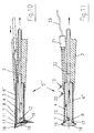
- einen Längsschnitt durch einen abgewandelten Applikator der dritten Ausführungsform nach der
Fig. 8 , - Fig. 11:
- einen anderen Längsschnitt des abgewandelten Applikators nach der
Fig. 10 , - Fig. 12:
- eine Seitenansicht eines Applikators in einer vierten Ausführungsform und
- Fig. 13:
- ein gegenüber der
Fig. 12 abgewandelter Applikator. - Der Applikator 1 gehört zu einer chirurgische Wasserstrahltrenneinrichtung, die aus einer Flüssigkeitstrenneinrichtung zum Trennen einer biologischen Struktur und einer entsprechenden Absaugeinrichtung besteht. Diese Wasserstrahltrenneinrichtung ist in der Medizintechnik inzwischen allgemein bekannt und braucht daher nicht näher gezeigt und beschrieben zu werden. Die Wasserstrahltrenneinrichtung besteht demnach aus einem Vorratsbehälter für eine sterile Flüssigkeit, einer Druckpumpe und einer Einspritzleitung und die Absaugeinrichtung besitzt einen Auffangbehälter für die Flüssigkeit und die abgetrennten Gewebeteile, eine Saugpumpe und eine Absaugleitung. Die Einspritzleitung der Wasserstrahltrenneinrichtung und die Absaugleitung der Absaugeinrichtung münden gemeinsam in den Applikator 1.
Der Applikator 1 aller Ausführungsformen außerFig. 13 besteht aus einem Handstück 2, das die Druckleitung 3 für den austretenden Wassertrennstrahl und die Saugleitung 4 für die aufgenommene Flüssigkeit und die abgetrennten Gewebeteile zusammenhält und sie zu einer, am distalen Ende des Applikators 1 befindlichen Arbeitssonde 5 führt. Dabei sind die Druckleitung 3 und die Saugleitung 4 getrennt voneinander, unmittelbar benachbart und achsparallel zueinander angeordnet. In der Saugleitung 4 befindet sich im Griffbereich des Handstückes 2 eine Bypassöffnung 13. - Nach den
Fig. 1 - 3 besitzt die Arbeitssonde 5 in der ersten Ausführungsform eine flache, nach unten offene und nach oben und zu den Seiten geschlossene Abdeckhaube 6, die auf ihrer nach unten offenen Seite eine umlaufende Dichtkante 7 besitzt. Die Dichtkante 7 ist dabei weitestgehend an die Körperformen des Patienten anpassbar und vorzugsweise mit einem besonderen Dichtmaterial ausgerüstet, das einen luftdichten Abschluss zur Körperoberfläche ermöglicht. Damit bildet sich eine hermetisch abgeschlossene Arbeitskammer 8 aus. Die Abdeckhaube 6 besteht aus einem transparenten Material, um eine Sicht von außen in die Arbeitskammer 8 und damit auf das Arbeitsfeld zu ermöglichen. Diese Abdeckhaube 6 ist vorzugsweise länglich gestreckt mit einer zum Handstück 2 nahen Seitenfläche 9 und einer zum Handstück 2 fernen Seitenfläche 10 ausgeformt. Die Druckleitung 3 für den Wasserstrahl mündet seitlich in der zum Handstück 2 nahen Seitenfläche 9 und bildet dort eine Austrittsdüse 11 aus. Diese Austrittsdüse 11 ist vorzugsweise eine Flachdüse. Die Saugleitung 4 ist oberhalb der Abdeckhaube 6 zur zum Handstück 2 fernen Seitenfläche 10 geführt, in der sie an der tiefsten Stelle der Abdeckhaube 6 einmündet und in diesem Bereich eine Saugöffnung 12 besitzt. Damit liegt die Saugöffnung 12 der Austrittsdüse 11 in gleicher Ebene gegenüber und damit im Wirkungsbereich der Austrittsdüse 11. Zur besseren Aufnahme des Wassertrennstrahls und der abgetrennten Gewebeteile ist die Abdeckhaube 6 im Bereich der Saugöffnung 12 trichterförmig ausgebildet. Diese Abdeckhaube 6 schirmt das Arbeitsfeld des Operateurs gegenüber dem Umfeld hermetisch ab. - Nach den
Fig. 4-7 besitzt die Arbeitssonde 5' in der zweiten Ausführungsform in gleicher Weise ein Handstück 2 mit einer Druckleitung 3, einer Saugleitung 4 und einer Abdeckhaube 6' mit einer Dichtkante 7, wobei die Druckleitung 3 und die Saugleitung 4 wiederum der Abdeckhaube 6' seitlich zugeführt sind. Dabei ist die Abdeckhaube 6' im Querschnitt rund ausgeführt und die Druckleitung 3 und die Saugleitung 4 am Umfang der Abdeckhaube 6' herumgeführt. Der umlaufende Teil der Saugleitung 4 befindet sich in der untersten Ebene und die Druckleitung 3 in der darüber liegenden Ebene der Abdeckhaube 6'. Dazu befinden sich im umlaufenden Teil der Saugleitung 4 vorzugsweise mehrere gleichmäßig verteilt angeordnete Saugöffnungen 12. Die darüber liegende Druckleitung 3 besitzt nach derFig. 6 vier gleichmäßig versetzt angeordnete Austrittsdüsen 11, sodass immer zwei der Austrittsdüsen 11 sich gegenüberliegen. Dabei sind die Austrittsdüsen 11 auf die darunter liegende Ebene gerichtet, in der sich die Saugöffnungen 12 befinden. Die vier oder auch mehr, möglichst in gerader Anzahl vorgesehenen Austrittsöffnungen 12 bilden somit in der Mitte der Abdeckhaube 6' einen Fokus.
Nach derFig. 7 sind lediglich zwei der Austrittsöffnungen 11 vorgesehen, die sich gegenüberliegen und in einer Ebene befinden, aber seitlich aneinander vorbei gerichtet sind. Dabei sind diese Verhältnisse so gewählt, dass ein von den Wassertrennstrahlen der beiden Austrittsdüsen 11 angegriffenes Gewebeteil in Rotation versetzt wird. Das unterstützt die Trennung. - Nach den
Fig. 8 und 9 besitzt die Arbeitssonde 5" eine zylindrische Abdeckhaube 6", die die Druckleitung 3 und die Saugleitung 4 im distalen Bereich des Applikators 1 in der Länge aufnimmt und umhüllt und fest mit dem Handgriff 2 verbunden ist. Am distalen Ende ist die Abdeckhaube 6" offen ausgeführt, sodass sich eine kreisrunde Dichtkante 7 ausbildet. Dabei sind die Druckleitung 3 und die Saugleitung 4 wieder achsparallel zueinander und zur zylindrischen Abdeckhaube 6" angeordnet. Zusammen sind die Druckleitung 3 und die Saugleitung 4 in besonderer Weise außermittig zur zylindrischen Abdeckhaube 6" in der Art angeordnet, dass sich die Saugleitung 4 achsfern und in unmittelbarer Nähe zur Innenwand der zylindrischen Abdeckhaube 6" und die Druckleitung 3 auf der achsnahen Seite der Saugleitung 4 befinden.
Die Saugleitung 4 besitzt am distalen Ende eine stirnseitige Saugöffnung 12 und wahlweise weitere Saugöffnungen 12, die am Umfang verteilt angeordnet sind. Dementsprechend endet die Saugleitung 4 in der Länge mit einem vorbestimmten Abstand oberhalb der Dichtkante 7 der Abdeckhaube 6", um die stirnseitige Saugöffnung 12 offen zu halten. Die Druckleitung 3 besitzt eine Austrittsdüse 11, die am äußersten distalen Ende und radial angeordnet ist und in Richtung weg von der Saugleitung 4 zeigt. - Die abgewandelte Arbeitssonde 5" in der dritten Ausführungsform nach den
Fig. 10 und 11 besitzt wiederum eine zylindrische Abdeckhaube 6", die aus einem transparenten Material besteht und die die Druckleitung 3 und die Saugleitung 4 im distalen Bereich des Applikators 1 in der Länge aufnimmt und umhüllt und die fest mit dem Handgriff 2 verbunden ist. Dabei sind die Druckleitung 3 und die Saugleitung 4 mit einem radialen Abstand zueinander und zur zylindrischen Abdeckhaube 6" in der Art angeordnet, dass die Enden der Druckleitung 3 und der Saugleitung 4 im distalen Bereich mit einem größten radialen Abstand zueinander angeordnet sind. Die Druckleitung 3 ist stirnseitig verschlossen, wobei die Austrittsdüse 11 radial und am äußersten Ende der Druckleitung 3 angeordnet ist. Die Austrittsdüse 11 ist vorzugsweise eine Flachdüse. Dabei zeigt die Austrittsdüse 11 in Richtung des Endes der Saugleitung 4. Dieses Ende der Saugleitung 4 besitzt eine stirnseitige und wahlweise weitere radiale Saugöffnungen 12.
Die Abdeckhaube 6" ist am distalen Ende wiederum offen ausgeführt. In der vorliegenden Ausführung verläuft das Ende der Abdeckhaube 6" abgeschrägt, sodass sich eine ovale Dichtkante 7 ausbildet. Auf diese Dichtkante 7 ist ein spezielles Dichtelement 16 aufgesetzt, das aus einem flexiblen Material besteht und somit an verschiedene Körperformen des Patienten anpassbar ist. Dieses Dichtelement 16 besitzt einen proximalen Haltering 17, der die Verbindung zur zylindrischen Abdeckhaube 6" gewährleistet, und eine distale Dichtlippe 18, die auf der Körperoberfläche des Patienten aufliegt. In besonderer Weise ist die distale Dichtlippe 18 im Bereich der Saugöffnungen 12 der Saugleitung 4 mit einer in axialer Richtung beweglichen Fangklappe 19 ausgestattet. Dabei ist die Fangklappe 19 zwischen einer ausgeklappten Stellung in der Ruheposition, so wie es dieFig. 10 zeigt, und einer nicht dargestellten eingeklappten Stellung in der aktiven Einsatzposition beweglich.
Die Abdeckhaube 6" besitzt im Bereich des Handstückes 2 ebenfalls eine erste Bypassöffnung 13, die von der Hand des Operateurs offen oder geschlossen gehalten wird und so bemessen ist, dass im offenen Zustand der Saugstrom über die Bypassöffnung 13 geleitet und damit ein Aufbau von Saugkräften am distalen Ende verhindert wird. In der Nähe dieser ersten Bypassöffnung 13 befindet sich eine zweite Bypassöffnung 20, die in Abstimmung mit der Leistung der Vakuumpumpe so bemessen ist, dass sich bei einer vollständigen Abdichtung am Dichtelement 16 und einer geschlossenen Bypassöffnung 13 ein definierter Saugstrom mit definierten Saugkräften einstellt.
Im Handstück 2 des Applikators 1 befindet sich weiterhin ein Vakuumsensor 21, der einerseits über eine Druckfühlerleitung 22 mit der Arbeitskammer 8 und andererseits über eine Signalleitung 23 mit der Flüssigkeitsförderpumpe verbunden ist. Dabei ist der Vakuumsensor 21 so ausgeführt und so mit der Flüssigkeitsförderpumpe gekoppelt, dass die Flüssigkeitsförderpumpe nur bei einem vorbestimmten Vakuumdruckbereich förderfähig ist. Eine Flüssigkeitsförderung und damit ein Austritt von Flüssigkeit aus der Austrittsdüse 11 sind außerhalb dieser Vakuumdruckdifferenz nicht möglich. - Nach der
Fig. 12 besitzt die Arbeitssonde 5" eine als Glocke ausgebildete Abdeckhaube 6"', die im unteren Bereich wiederum offen und mit einer kreisrunden Dichtkante 7 ausgestattet ist. In der Glockenkuppel der Abdeckhaube 6'" befindet sich eine Öffnung, in der die wiederum achsparallel nebeneinander liegenden Druckleitung 3 und Saugleitung 4 hindurchgeführt sind. In dieser Öffnung der Glockenkupplung ist ein flexibles Halte- und Dichtelement 14 eingesetzt, welches die Druckleitung 3 und die Saugleitung 4 hält und den Zwischenraum zwischen der Abdeckhaube 6"' und der Druckleitung 3 und der Saugleitung 4 nach außen abdichtet. Dabei ist Halte- und Dichtelement 14 fest mit der Abdeckhaube 6'" verbunden und gegenüber der Druckleitung 3 und der Saugleitung 4 gleitend ausgelegt. Damit ist die Druckleitung 3 und die Saugleitung 4 sowohl in der Höhe als auch in der Winkelstellung verstellbar, sodass die distalen Enden der Druckleitung 3 und der Saugleitung 4 zusammen jeden Punkt der Arbeitsfläche innerhalb der Abdeckhaube 6'" erreichen können. Neben dem flexiblen Halte- und Dichtelement 14 in der Glockenkupplung oder alternativ dazu, können weitere jeweils mit einem Halte- und Dichtelement 14 verschlossene Öffnungen zum wahlweisen Hindurchführen der Druckleitung 3 und der Saugleitung 4 vorgesehen sein. Damit kann die Zugänglichkeit zum Arbeitsfeld des Operateurs verbessert werden. - Die distalen Enden der Druckleitung 3 und der Saugleitung 4 sind wiederum in bekannter Weise mit einer radialen und von der Saugleitung 4 weg gerichteten Austrittsdüse 11 und einer stirnseitigen und wahlweise weiterer radialer Saugöffnungen 12 ausgestattet.
- Gemäß der
Fig. 13 besitzt die Abdeckhaube 6'" im Bereich seiner Dichtkante 7 ein umlaufendes Dichtelement 15, das auswechselbar an der Abdeckhaube 6'" befestigt ist und mit seiner Dichtkante 7 an bestimmte Körperteile des Patienten angepasst ist. Dieses Dichtelement 15 kann gegen andere Dichtelemente 15 mit einer anderen Kontur der Dichtkante 7 ausgewechselt werden. Das Dichtelement 15 kann auch aus einem flexiblen Material bestehen und damit selbstanpassend ausgeführt sein. Im Dichtelement 15 ist die ebenfalls umlaufend ausgeführte Absaugleitung 4 integriert und direkt abgeleitet, wobei die Absaugleitung 4 in seinem umlaufenden Bereich mehrere Saugöffnungen 12 aufweist. Dementsprechend ist durch das Halte- und Dichtelement 14 lediglich die Druckleitung 3 hindurch geführt, wodurch während der Operation auch nur diese Druckleitung 3 gehandhabt wird. - Während des Betriebes der Wasserstrahltrenneinrichtung stellt sich in der Druckleitung 3 ein vorbestimmter Wasserdruck ein, der im Zusammenwirken mit der Austrittsdüse 11 einen entsprechenden vorzugsweise flachen Wassertrennstrahl ausbildet. Die Saugleitung 4 ist zunächst drucklos, weil die Bypassöffnung 13 geöffnet ist und so einen Nebensaugstrom erzeugt. Mit dem Verschluss dieser Bypassöffnung 13 durch den Operateur baut sich in der Arbeitskammer 8 der Abdeckhaube 6, 6', 6", 6'" ein Unterdruck auf, der das im Bereich der Arbeitssonde 5, 5', 5", 5"', 5"" befindliche Gewebe anhebt und es gegen die Dichtkante 7 der Abdeckhaube 6, 6', 6", 6"' drückt. Damit ist das Arbeitsfeld gegenüber dem Umfeld hermetisch abgeschirmt, sodass kein Wasser und damit keine Bakterien aus dem Arbeitsfeld austreten können. Gleichzeitig wird das abzutrennende Gewebe durch die Kraft des Saugstromes innerhalb der Abdeckhaube 6 angehoben und in eine starke Straffung und in eine günstige Position für den Trennvorgang gebracht. Der Wasserstrahl verrichtet dann Arbeit, in dem er in intelligenter Weise zwischen die Gewebezellen dringt, sie aufweitet und weiter spannt und sie voneinander trennt. Gewebezellen werden dabei kaum beschädigt. Der Saugstrom erfasst die abgetrennten Gewebeteile zusammen mit dem sich ansammelnden Wasser und befördert sie durch die Saugöffnungen 12 zum Aufnahmebehälter.
Bei der ersten Ausführungsform gemäß derFig. 1 - 3 sind der Trennstrahl und der Saugstrom innerhalb der Abdeckhaube 6 gleichgerichtet, sodass sich die beiden Kräfte überlagern und eine hohe Trenn- und Saugwirkung erzielen.
Der Applikator 1 in der zweiten Ausführungsform nach denFig. 4 - 7 entwickelt mehrere Wassertrennstrahlen, die sich gegenüberliegen. Damit werden die Wassertrennstrahlen fokussiert, wodurch das abzutrennende Gewebe allseitig untergraben, angehoben und im Fokus zerkleinert wird. Durch die Anordnung des Austrittsdüsen 11 nach derFig. 7 wird ein zusätzlicher Drehimpuls auf das abzutrennende Gewebe ausgeübt, der das Trennen weiter erleichtert.
In den dritten und vierten Ausführungsformen nach denFig. 8, 9 ,12 und13 ist der Wassertrennstrahl von der Saugöffnung 12 weggerichtet. Dabei wird der trennende Wasserstrahl von der runden Innenwand der Abdeckhaube 6", 6'" erfasst und umgelenkt, sodass der Wassertrennstrahl an der Innenwand entlang gleitet und zur Saugöffnung 12 zurückgeführt wird. - Nach dem erfolgten Debridement wird die Druckerzeugung für den Wasserstrahl abgeschaltet und die Bypassöffnung 13 vom Operateur geöffnet, sodass sich der Saugstrom entspannt und das an der Dichtkante 7 der Abdeckhaube 6, 6', 6", 6"' angesaugte Gewebe wieder freigibt. Danach wird der Applikator 1 ins nächste Arbeitsfeld umgesetzt und neu in Bearbeitung genommen.
Dieses Umsetzen des Applikators 1 innerhalb der Wunde oder des Geschwürs erübrigt sich bei der Ausführungsform nach derFig. 12 und13 weitestgehend, weil die glockenförmige Abdeckhaube 6"' so großvolumig ausgeführt ist, dass sie die Wunde oder das Geschwür in der Regel im Ganzen überdeckt. Die Bearbeitung Zug um Zug erfolgt hierbei durch die vertikale Anhebung und die horizontale Auslenkung der gebündelten Druckleitung 3 und Saugleitung 4 innerhalb der Arbeitskammer 8.
Der abgewandelte Applikator 1 in der dritten Ausführungsform nach denFig. 10, 11 besitzt darüber hinaus gehende Funktionen und Vorteile. So ergibt der abgeschrägte Verlauf der distalen Dichtkante 7 eine ovale Arbeitsfläche am Körper des Patienten und damit einen größten möglichen Abstand zwischen der Austrittsdüse 11 und den Saugöffnungen 12. Mit dieser abgeschrägten Dichtkante 7 bekommt der Applikator 1 eine handlichere Arbeitsposition. Mit dem Verschließen der ersten Bypassöffnung 13 fließt ein Saugstrom über die zweite Bypassöffnung 20, der Arbeitskammer 8 und den Saugöffnungen 12 in der Saugleitung 4. Dieser Saugstrom bestimmt zunächst die Größe des Vakuums und sorgt auch während der Wasserstahltrennung für einen unterstützenden Mitreißeffekt für das abgetrennte Gewebe. Das auf Grund der Saugleistung der Vakuumpumpe einerseits und des Durchflusswiderstandes an der zweiten Bypassöffnung 20 andererseits entstehende Vakuum zieht das Körpergewebe des Patienten in abdichtender Weise gegen die Dichtkante 7. An besonderen Körperstellen des Patienten, die eine derartige Gewebeverschiebung nicht oder nicht ausreichend zulassen, wie es sich beispielsweise im Bereich von Gliedmaßen ergibt, saugt das Vakuum das flexible Dichtelement 16 in die Körperdellen und gewährleistet damit auch in diesen Fällen eine funktionsbedingte Abdichtung. Dieser Vakuumdruck wird vom Vakuumsensor 21 überwacht. Nachdem sich in der Arbeitskammer 8 ein vorbestimmter Vakuumdruck eingestellt hat, signalisiert der Vakuumsensor 21 einen Steuerbefehl zur Aktivierung der Flüssigkeitsförderpumpe. Der erzeugte Wasserstrahl verrichtet dann seine Arbeit in bereits beschriebener intelligenter Weise.
Nach dem erfolgten Debridement öffnet der Operateur die Bypassöffnung 13, sodass sich das Vakuum entspannt und sich das Dichtelement 16 von der Körperoberfläche löst. Der Vakuumsensor 21 erfasst diese Druckveränderung in der Arbeitskammer 8 und gibt ein Steuersignal an die Flüssigkeitsförderpumpe, um sie sofort abschalten zu lassen. Dieses Steuersignal leitet gleichzeitig eine kurze Umkehrung der Förderrichtung ein, um ein Nachlaufen der Flüssigkeitsförderpumpe und damit eine begrenzte Weiterförderung zu minimieren. Der Operateur hebt also unmittelbar nach dem Öffnen der ersten Bypassöffnung 13 den Appplikator 1 von der Körperoberfläche des Patienten ab, um es an einer nächsten Körperstelle wieder ansetzen zu können. Auf Grund der sensorgestützten An- und Abschaltung der Flüssigkeitsförderpumpe wird ein unkontrolliertes Austreten von mit Bakterien versetzter Flüssigkeit in das Umfeld unterbunden. Eine zusätzliche Sicherheit gegen das unerwünschte Austreten von verunreinigter Flüssigkeit tritt durch die besondere Funktion des Dichtelementes 16 ein. Auf Grund der natürlichen Bewegung des Operateurs löst sich beim Abheben des Applikators 1 zunächst der obere Teil der Dichtkante 7, in dessen Bereich sich die Austrittsdüse 11 befindet, während der untere Teil im Bereich der Saugöffnungen 12 noch an der Körperoberfläche verweilt. Dadurch kommt es zum Aufklappen der Fangklappe 19, die einen wider erwarten dennoch kurzzeitig vorhandenen Druckflüssigkeitsstrahl aufnimmt und in das Innere der Arbeitskammer 8 umlenkt. Ein Austreten des Druckflüssigkeitsstrahls aus dem Bereich der Arbeitskammer 8 in die Nähe des Operateurs wird dadurch verhindert. Nach dem Umsetzen des Applikators 1 wiederholt sich diese Funktion an einer anderen Körperposition. -
- 1
- Applikator
- 2
- Handstück
- 3
- Druckleitung
- 4
- Saugleitung
- 5
- Arbeitssonde
- 6
- Abdeckhaube
- 7
- Dichtkante
- 8
- Arbeitskammer
- 9
- nahe Seitenfläche
- 10
- ferne Seitenfläche
- 11
- Austrittsdüse
- 12
- Saugöffnung
- 13
- Bypassöffnung
- 14
- flexibles Halte- und Dichtelement
- 15
- Dichtelement
- 16
- Dichtelement
- 17
- Haltering
- 18
- Dichtlippe
- 19
- Fangklappe
- 20
- zweite Bypassöffnung
- 21
- Vakuumsensor
- 22
- Druckfühlerleitung
- 23
- Signalleitung
Claims (16)
- Applikator für eine Wasserstrahltranneinrichtung, insbesondere zur Behandlung von Wunden und Geschwüren, bestehend aus einem Handgriff (2), einer Druckleitung (3) und einer Saugleitung (4), wobei die Druckleitung (3) mindestens ein Austrittsdüse (11) und die Saugleitung (4) mindestens eine Saugöffnung (12) besitzt und die Austrittsdüse (11) und die Saugöffnung (12) in einer Abdeckhaube (6, 6', 6", 6'") angeordnet sind und die Abdeckhaube (6, 6', 6", 6''') vorzugsweise aus einem transparenten Material besteht,
dadurch gekennzeichnet, dass die Abdeckhaube (6, 6', 6", 6"') mit Körperteilen des Patienten eine definiert vakuumverschlossene und von einem Vakuumsensor (21) überwachte Arbeitskammer (8) ausbildet. - Applikator nach Anspruch 1,
dadurch gekennzeichnet, dass die Austrittsdüse (11) der Druckleitung (3) auf die Saugöffnung (12) der Saugleitung (4) gerichtet ist. - Applikator nach Anspruch 1,
dadurch gekennzeichnet, dass die Austrittsdüse (11) radial vorzugsweise an der zum Handstück (2) nahen Seitenfläche (9) und die Saugöffnung (12) radial an der zum Handstück (2) fernen Seitenfläche (10) angeordnet sind. - Applikator nach Anspruch 1,
dadurch gekennzeichnet, dass die Abdeckhaube (6') an ihrem Umfang in einer oberen Ebene mindestens eine Austrittsdüse (11) und in einer unteren Ebene mindestens eine Saugöffnung (12) besitzt. - Applikator nach Anspruch 4,
dadurch gekennzeichnet, dass die Austrittsdüsen (11) so angeordnet sind, dass die austretenden Wasserstrahlen einen Focus ausbilden. - Applikator nach Anspruch 4,
dadurch gekennzeichnet, dass die Austrittsdüsen (11) so angeordnet sind, dass die austretenden Wasserstrahlen auf Abstand einander begegnen und einen mittigen Drall erzeugen. - Applikator nach Anspruch 2,
dadurch gekennzeichnet, dass die Abdeckhaube (6") vorzugsweise zylindrisch ausgebildet ist, die Druckleitung (3) und die Saugleitung (4) in der Länge umhüllt, und am distalen Ende offen ausgeführt ist, wobei die Druckleitung (3) und die Saugleitung (4) außermittig zur Abdeckhaube (6") in der Art angeordnet sind, dass sich die Austrittsdüse (11) der Druckleitung (3) und die Saugöffnung (12) der Saugleitung (4) im distalen Bereich mit einem größten radialen Abstand zueinander befinden. - Applikator nach Anspruch 1,
dadurch gekenazeichnet, dass die Austrittsdüse (11) der Druckleitung (3) radial und von der Saugöffnung (12) weg und gegen die Abdeckhaube (6", 6"') gerichtet ist. - Applikator nach Anspruch 8,
dadurch gekennzeichnet, dass die Abdeckhaube (6") vorzugsweise zylindrisch ausgebildet ist, die Druckleitung (3) und die Saugleitung (4) in der Länge umhüllt, und am distalen Ende offen ausgeführt ist, wobei die Druckleitung (3) und die Saugleitung (4) außermittig zur Abdeckhaube (6") in der Art angeordnet sind, dass sich die Saugleitung (4) achsfern und die Druckleitung (3) auf der achsnahen Seite der Saugleitung (4) befinden. - Applikator nach Anspruch 8,
dadurch gekennzeichnet, dass die Abdeckhaube (6"') glockenförmig ausgebildet ist und die Druckleitung (3) und die Saugleitung (4) in der Länge umhüllt, wobei die Druckleitung (3) und die Saugleitung (4) vorzugsweise parallel zusammen und in der Abdeckhaube gelenkig und vorstellbar gelagert sind. - Applikator nach Anspruch 10,
dadurch gekennzeichnet, dass mindestens ein Gelenk in der Abdeckhaube (6"') vorgesehen ist, das jeweils vorzugsweise als ein flexibles Halte- und Dichtelement (14) ausgebildet ist und welches bei Nichtbenutzung verschließbar ist. - Applikator nach Anspruch 1,
dadurch gekennzeichnet, dass die Abdeckhaube (6,6', 6", 6"') ein an die Körperteile anpassbares Dichtelement (15, 16) mit einer Dichtkante (7, 18) besitzt. - Applikator nach Anspruch 12,
dadurch gekennzeichnet, dass das Dichtelement (15, 16) im Strahlbereich der Austrittsdüse (11) eine Fangklappe (19) besitzt, die während der Abwendung des Applikators 1 in die Arbeitskammer (8) eingeklappt und die mit dem Abheben des Applikators von der Behandlungsstelle in Richtung der Körperoberfläche ausklappt. - Applikator nach Anspruch 1,
dadurch gekennzeichnet, dass in der Abdeckhaube (6, 6', 6", 6"') über die Saugleitung (4) ein vorzugsweise pulsierendes, das Gewebe stimulierendes Vakuum erzeugt wird. - Applikator nach Anspruch 1,
dadurch gekennzeichnet, dass an der Arbeitskammer (8) ein Vakuumsensor (21) angeschlossen ist, der über eine Signalleitung (23) in der Art mit der Flüssigkeitsföxderpumpe verbunden ist, dass die Flüssigkeitsförderpumpe nur innerhalb eines vorbestimmten Vakuumdruckbereiches förderfähig ist, der über den Vakuumsensor (21) ausgewertet wird. - Applikator nach Anspruch 15,
dadurch gekennzeichnet, dass der Vakuumsensor (21) in der Art mit der Flüssigkeitsförderpumpe verbunden ist, dass mit der Abschaltung der Flüssigkeitsförderpumpc die Förderrichtung der Flüssigkeitsförderpumpe kurzzeitig umgekehrt wird.
Applications Claiming Priority (2)
| Application Number | Priority Date | Filing Date | Title |
|---|---|---|---|
| DE202006018986U DE202006018986U1 (de) | 2006-12-16 | 2006-12-16 | Applikator für eine Wasserstrahleinrichtung, insbesondere zur Behandlung von Wunden und Geschwüren |
| PCT/DE2007/002057 WO2008074284A2 (de) | 2006-12-16 | 2007-11-14 | Applikator für eine wasserstrahltrenneinrichtung, insbesondere zur behandlung von wunden und geschwüren |
Publications (2)
| Publication Number | Publication Date |
|---|---|
| EP2099512A2 EP2099512A2 (de) | 2009-09-16 |
| EP2099512B1 true EP2099512B1 (de) | 2010-04-21 |
Family
ID=39311575
Family Applications (1)
| Application Number | Title | Priority Date | Filing Date |
|---|---|---|---|
| EP07846333A Not-in-force EP2099512B1 (de) | 2006-12-16 | 2007-11-14 | Applikator für eine wasserstrahltrenneinrichtung, insbesondere zur behandlung von wunden und geschwüren |
Country Status (5)
| Country | Link |
|---|---|
| US (1) | US20090326489A1 (de) |
| EP (1) | EP2099512B1 (de) |
| AT (1) | ATE464921T1 (de) |
| DE (2) | DE202006018986U1 (de) |
| WO (1) | WO2008074284A2 (de) |
Families Citing this family (23)
| Publication number | Priority date | Publication date | Assignee | Title |
|---|---|---|---|---|
| WO2010006564A1 (de) * | 2008-07-15 | 2010-01-21 | Human Med Ag | Vorrichtung zur chirurgischen behandlung biologischer strukturen |
| IT1395482B1 (it) * | 2009-09-02 | 2012-09-28 | Enea | Apparato, per trattamento selettivo di partizioni limitate della superficie corporea di una persona |
| EP3861969A1 (de) | 2010-08-05 | 2021-08-11 | ForSight Vision4, Inc. | Injektorvorrichtung zur arzneimittelabgabe |
| US10398592B2 (en) | 2011-06-28 | 2019-09-03 | Forsight Vision4, Inc. | Diagnostic methods and apparatus |
| PT2755600T (pt) | 2011-09-16 | 2021-04-19 | Forsight Vision4 Inc | Aparelhos de troca de fluidos |
| DE102013008964A1 (de) | 2013-05-22 | 2014-11-27 | Gmbu E.V., Fachsektion Dresden | Vorrichtung zur Behandlung von Problemwunden |
| WO2015032863A1 (de) | 2013-09-06 | 2015-03-12 | Medaxis Ag | Handstück zur behandlung von wunden |
| DE102014208074A1 (de) * | 2014-04-29 | 2015-10-29 | Söring GmbH | Schutzhaube für ein chirurgisches Operationsfeld |
| WO2015171754A1 (en) * | 2014-05-07 | 2015-11-12 | Massachusetts Institute Of Technology | Debridement apparatus using linear lorentz-force motors |
| EP3132766B1 (de) * | 2015-08-21 | 2020-10-07 | Medaxis Ag | Schutzabdeckung |
| US11172955B2 (en) | 2017-08-09 | 2021-11-16 | Boston Scientific Scimed, Inc. | Endoscopy system and related methods |
| CN111655206B (zh) | 2017-11-21 | 2022-10-14 | 弗赛特影像4股份有限公司 | 用于可扩展端口递送系统的流体交换装置及使用方法 |
| CN108042857B (zh) * | 2018-02-07 | 2024-07-16 | 中国人民解放军第四军医大学 | 带有伤口出脓吸取脓液的烧伤护理装置 |
| JP7142290B2 (ja) * | 2018-10-02 | 2022-09-27 | 国立大学法人福井大学 | 医療用ドレーンチューブ |
| WO2020163343A1 (en) | 2019-02-04 | 2020-08-13 | The Regents Of The University Of Michigan | Device and method for wound irrigation and debridement |
| WO2020181290A1 (en) | 2019-03-07 | 2020-09-10 | Procept Biorobotics Corporation | Robotic arms and methods for tissue resection and imaging |
| CN109938847A (zh) * | 2019-04-23 | 2019-06-28 | 黄安华 | 一种面部注水防溅器 |
| US11071601B2 (en) | 2019-11-11 | 2021-07-27 | Procept Biorobotics Corporation | Surgical probes for tissue resection with robotic arms |
| MX2022011624A (es) * | 2020-03-20 | 2022-10-13 | Inovio Pharmaceuticals Inc | Dispositivos de electroporacion asistidos por vacio y sistemas y metodos relacionados. |
| US11096753B1 (en) | 2020-06-26 | 2021-08-24 | Procept Biorobotics Corporation | Systems and methods for defining and modifying range of motion of probe used in patient treatment |
| US20240189499A1 (en) * | 2021-05-13 | 2024-06-13 | Tavger Ltd | Dynamic negative pressure wound therapy system |
| USD1033637S1 (en) | 2022-01-24 | 2024-07-02 | Forsight Vision4, Inc. | Fluid exchange device |
| CN117599277A (zh) * | 2024-01-22 | 2024-02-27 | 山东第一医科大学附属省立医院(山东省立医院) | 一种神经外科手术用清洗装置 |
Family Cites Families (15)
| Publication number | Priority date | Publication date | Assignee | Title |
|---|---|---|---|---|
| US3184156A (en) * | 1957-09-06 | 1965-05-18 | Medard W Welch | Skin stimulating and cleaning device and pump therefor |
| US5037431A (en) * | 1989-11-03 | 1991-08-06 | The Curators Of The University Of Missouri | Surgical liquid lance apparatus |
| DE4018736A1 (de) * | 1990-06-12 | 1992-01-02 | Wigbert S Prof Dr Med Rau | Hochdruck-aspirationskatheter zur wiedereroeffnung von krankhaft verschlossenen gefaessen |
| US5496267A (en) * | 1990-11-08 | 1996-03-05 | Possis Medical, Inc. | Asymmetric water jet atherectomy |
| US5636643A (en) * | 1991-11-14 | 1997-06-10 | Wake Forest University | Wound treatment employing reduced pressure |
| DE4201992A1 (de) * | 1992-01-25 | 1993-07-29 | Hp Medica Gmbh Fuer Medizintec | Hochdruck-fluessigkeitsdispensor zur abgabe von steriler fluessigkeit |
| US5547376A (en) * | 1992-06-18 | 1996-08-20 | Harrel; Stephen K. | Methods and apparatus for containing and recovering abrasive powders from an abrasive polisher |
| GB9520209D0 (en) * | 1995-09-25 | 1995-12-06 | Cawley R | Skin cleaning apparatus |
| US5941859A (en) * | 1997-03-17 | 1999-08-24 | Lerman; Benjamin S. | Wound irrigation shield with fluid scavenging |
| DE69927153T2 (de) * | 1998-06-19 | 2006-07-06 | Eschmann Holdings Ltd., Lancing | VERFAHREN ZUR ERZEUGUNG EINER PULSFOLGE EINES STERILEN FLÜSSIGKEITSSTRAHLS Für MEDIZINISCHE ZWECKE |
| DE59812834D1 (de) * | 1998-10-26 | 2005-07-07 | Human Med Ag | Vorrichtung zum Entfernen von Krankheitsherden in der Human- und Veterinärmedizin |
| US6375635B1 (en) * | 1999-05-18 | 2002-04-23 | Hydrocision, Inc. | Fluid jet surgical instruments |
| CA2495911C (en) * | 2001-11-21 | 2011-06-07 | Hydrocision, Inc. | Liquid jet surgical instruments incorporating channel openings aligned along the jet beam |
| DE20205274U1 (de) * | 2002-04-05 | 2003-08-07 | Kaltenbach & Voigt GmbH & Co. KG, 88400 Biberach | Medizinisches, insbesondere dentalmedizinisches Handstück mit einem Auslass für ein abrasives Strömungsmedium und Spritzschutz für den Auslass |
| US8162966B2 (en) * | 2002-10-25 | 2012-04-24 | Hydrocision, Inc. | Surgical devices incorporating liquid jet assisted tissue manipulation and methods for their use |
-
2006
- 2006-12-16 DE DE202006018986U patent/DE202006018986U1/de not_active Expired - Lifetime
-
2007
- 2007-11-14 AT AT07846333T patent/ATE464921T1/de active
- 2007-11-14 DE DE502007003551T patent/DE502007003551D1/de active Active
- 2007-11-14 EP EP07846333A patent/EP2099512B1/de not_active Not-in-force
- 2007-11-14 WO PCT/DE2007/002057 patent/WO2008074284A2/de not_active Ceased
-
2009
- 2009-06-16 US US12/457,581 patent/US20090326489A1/en not_active Abandoned
Also Published As
| Publication number | Publication date |
|---|---|
| WO2008074284A3 (de) | 2008-09-18 |
| DE502007003551D1 (de) | 2010-06-02 |
| EP2099512A2 (de) | 2009-09-16 |
| US20090326489A1 (en) | 2009-12-31 |
| DE202006018986U1 (de) | 2008-04-17 |
| ATE464921T1 (de) | 2010-05-15 |
| WO2008074284A2 (de) | 2008-06-26 |
Similar Documents
| Publication | Publication Date | Title |
|---|---|---|
| EP2099512B1 (de) | Applikator für eine wasserstrahltrenneinrichtung, insbesondere zur behandlung von wunden und geschwüren | |
| DE69014832T2 (de) | Atherektomie-Katheter mit Faserenden. | |
| DE19722075C1 (de) | Vorrichtung zur Applikation von Wirkstoffen an einer Wundoberfläche | |
| DE69209813T2 (de) | Absaugrohr zur Verwendung bei chirurgischen Eingriffen | |
| DE69624938T2 (de) | Chirurgisches schneidinstrument mit ansaugung und innerer berieselung | |
| DE69533677T2 (de) | Vorrichtung zum entfernen von stoffen aus dem körper | |
| DE4229873C1 (de) | Endoskopischer Prüfverschluß | |
| EP3808296B1 (de) | Vorrichtung zur lokalen applikation von und/oder zum spülen mit fluiden | |
| EP2560554B1 (de) | Invasives instrument zur bearbeitung von gefässen | |
| EP3132766B1 (de) | Schutzabdeckung | |
| DE10229137A1 (de) | Chirurgisches Instrument | |
| WO2011110316A1 (de) | Medizinische vorrichtung zum entfernen von konkrementen aus körperhohlorganen | |
| DE19631677C1 (de) | Endoskopisches Gerät für Perforanzvenen | |
| EP3041526B1 (de) | Handstück zur reinigung von wunden | |
| WO1991017729A1 (de) | Gerät für die spülung und drainierung von wunden | |
| EP0630617A1 (de) | Aspirationskatheteranordnung | |
| DE19923260A1 (de) | Endo-Beutel mit einem Inflations-Aufnahmemundstück und Instrument zum Einführen des Endo-Beutels | |
| EP2892581B1 (de) | Medizinischer drainageschlauch | |
| DE102008059547B4 (de) | Vorrichtung zum Entfernen von Konkrementen in Körpergefäßen | |
| EP1795217B1 (de) | Absaugkanüle | |
| DE10033278B4 (de) | Chirurgische Einrichtung zur Entnahme von Gewebezellen aus einer biologischen Struktur | |
| LU601203B1 (de) | Ein Wundreinigungs- und Verbandwechselgerät für die Pflege von Frakturverletzungen | |
| DE4238596C2 (de) | Berge-Vorrichtung | |
| DE102008004131A1 (de) | Laparoskopische Trokarhülse | |
| DE1441911C (de) |
Legal Events
| Date | Code | Title | Description |
|---|---|---|---|
| PUAI | Public reference made under article 153(3) epc to a published international application that has entered the european phase |
Free format text: ORIGINAL CODE: 0009012 |
|
| 17P | Request for examination filed |
Effective date: 20090702 |
|
| AK | Designated contracting states |
Kind code of ref document: A2 Designated state(s): AT BE BG CH CY CZ DE DK EE ES FI FR GB GR HU IE IS IT LI LT LU LV MC MT NL PL PT RO SE SI SK TR |
|
| GRAP | Despatch of communication of intention to grant a patent |
Free format text: ORIGINAL CODE: EPIDOSNIGR1 |
|
| RTI1 | Title (correction) |
Free format text: APPLICATOR FOR A WATER JET SEPARATING DEVICE, PARTICULARLY FOR THE TREATMENT OF WOUNDS AND ABSCESSES |
|
| GRAS | Grant fee paid |
Free format text: ORIGINAL CODE: EPIDOSNIGR3 |
|
| GRAA | (expected) grant |
Free format text: ORIGINAL CODE: 0009210 |
|
| DAX | Request for extension of the european patent (deleted) | ||
| AK | Designated contracting states |
Kind code of ref document: B1 Designated state(s): AT BE BG CH CY CZ DE DK EE ES FI FR GB GR HU IE IS IT LI LT LU LV MC MT NL PL PT RO SE SI SK TR |
|
| REG | Reference to a national code |
Ref country code: GB Ref legal event code: FG4D Free format text: NOT ENGLISH |
|
| REG | Reference to a national code |
Ref country code: CH Ref legal event code: EP |
|
| REG | Reference to a national code |
Ref country code: IE Ref legal event code: FG4D Free format text: LANGUAGE OF EP DOCUMENT: GERMAN |
|
| REF | Corresponds to: |
Ref document number: 502007003551 Country of ref document: DE Date of ref document: 20100602 Kind code of ref document: P |
|
| REG | Reference to a national code |
Ref country code: NL Ref legal event code: VDEP Effective date: 20100421 |
|
| LTIE | Lt: invalidation of european patent or patent extension |
Effective date: 20100421 |
|
| PG25 | Lapsed in a contracting state [announced via postgrant information from national office to epo] |
Ref country code: LT Free format text: LAPSE BECAUSE OF FAILURE TO SUBMIT A TRANSLATION OF THE DESCRIPTION OR TO PAY THE FEE WITHIN THE PRESCRIBED TIME-LIMIT Effective date: 20100421 Ref country code: NL Free format text: LAPSE BECAUSE OF FAILURE TO SUBMIT A TRANSLATION OF THE DESCRIPTION OR TO PAY THE FEE WITHIN THE PRESCRIBED TIME-LIMIT Effective date: 20100421 Ref country code: SE Free format text: LAPSE BECAUSE OF FAILURE TO SUBMIT A TRANSLATION OF THE DESCRIPTION OR TO PAY THE FEE WITHIN THE PRESCRIBED TIME-LIMIT Effective date: 20100421 Ref country code: ES Free format text: LAPSE BECAUSE OF FAILURE TO SUBMIT A TRANSLATION OF THE DESCRIPTION OR TO PAY THE FEE WITHIN THE PRESCRIBED TIME-LIMIT Effective date: 20100801 |
|
| REG | Reference to a national code |
Ref country code: IE Ref legal event code: FD4D |
|
| PG25 | Lapsed in a contracting state [announced via postgrant information from national office to epo] |
Ref country code: FI Free format text: LAPSE BECAUSE OF FAILURE TO SUBMIT A TRANSLATION OF THE DESCRIPTION OR TO PAY THE FEE WITHIN THE PRESCRIBED TIME-LIMIT Effective date: 20100421 Ref country code: SI Free format text: LAPSE BECAUSE OF FAILURE TO SUBMIT A TRANSLATION OF THE DESCRIPTION OR TO PAY THE FEE WITHIN THE PRESCRIBED TIME-LIMIT Effective date: 20100421 Ref country code: LV Free format text: LAPSE BECAUSE OF FAILURE TO SUBMIT A TRANSLATION OF THE DESCRIPTION OR TO PAY THE FEE WITHIN THE PRESCRIBED TIME-LIMIT Effective date: 20100421 Ref country code: IS Free format text: LAPSE BECAUSE OF FAILURE TO SUBMIT A TRANSLATION OF THE DESCRIPTION OR TO PAY THE FEE WITHIN THE PRESCRIBED TIME-LIMIT Effective date: 20100821 |
|
| PG25 | Lapsed in a contracting state [announced via postgrant information from national office to epo] |
Ref country code: PL Free format text: LAPSE BECAUSE OF FAILURE TO SUBMIT A TRANSLATION OF THE DESCRIPTION OR TO PAY THE FEE WITHIN THE PRESCRIBED TIME-LIMIT Effective date: 20100421 Ref country code: CY Free format text: LAPSE BECAUSE OF FAILURE TO SUBMIT A TRANSLATION OF THE DESCRIPTION OR TO PAY THE FEE WITHIN THE PRESCRIBED TIME-LIMIT Effective date: 20100616 |
|
| PG25 | Lapsed in a contracting state [announced via postgrant information from national office to epo] |
Ref country code: IE Free format text: LAPSE BECAUSE OF FAILURE TO SUBMIT A TRANSLATION OF THE DESCRIPTION OR TO PAY THE FEE WITHIN THE PRESCRIBED TIME-LIMIT Effective date: 20100421 Ref country code: PT Free format text: LAPSE BECAUSE OF FAILURE TO SUBMIT A TRANSLATION OF THE DESCRIPTION OR TO PAY THE FEE WITHIN THE PRESCRIBED TIME-LIMIT Effective date: 20100823 Ref country code: DK Free format text: LAPSE BECAUSE OF FAILURE TO SUBMIT A TRANSLATION OF THE DESCRIPTION OR TO PAY THE FEE WITHIN THE PRESCRIBED TIME-LIMIT Effective date: 20100421 Ref country code: EE Free format text: LAPSE BECAUSE OF FAILURE TO SUBMIT A TRANSLATION OF THE DESCRIPTION OR TO PAY THE FEE WITHIN THE PRESCRIBED TIME-LIMIT Effective date: 20100421 |
|
| PLBE | No opposition filed within time limit |
Free format text: ORIGINAL CODE: 0009261 |
|
| STAA | Information on the status of an ep patent application or granted ep patent |
Free format text: STATUS: NO OPPOSITION FILED WITHIN TIME LIMIT |
|
| PG25 | Lapsed in a contracting state [announced via postgrant information from national office to epo] |
Ref country code: SK Free format text: LAPSE BECAUSE OF FAILURE TO SUBMIT A TRANSLATION OF THE DESCRIPTION OR TO PAY THE FEE WITHIN THE PRESCRIBED TIME-LIMIT Effective date: 20100421 Ref country code: CZ Free format text: LAPSE BECAUSE OF FAILURE TO SUBMIT A TRANSLATION OF THE DESCRIPTION OR TO PAY THE FEE WITHIN THE PRESCRIBED TIME-LIMIT Effective date: 20100421 Ref country code: RO Free format text: LAPSE BECAUSE OF FAILURE TO SUBMIT A TRANSLATION OF THE DESCRIPTION OR TO PAY THE FEE WITHIN THE PRESCRIBED TIME-LIMIT Effective date: 20100421 |
|
| 26N | No opposition filed |
Effective date: 20110124 |
|
| BERE | Be: lapsed |
Owner name: HUMAN MED A.G. Effective date: 20101130 |
|
| PG25 | Lapsed in a contracting state [announced via postgrant information from national office to epo] |
Ref country code: GR Free format text: LAPSE BECAUSE OF FAILURE TO SUBMIT A TRANSLATION OF THE DESCRIPTION OR TO PAY THE FEE WITHIN THE PRESCRIBED TIME-LIMIT Effective date: 20100722 |
|
| PG25 | Lapsed in a contracting state [announced via postgrant information from national office to epo] |
Ref country code: MC Free format text: LAPSE BECAUSE OF NON-PAYMENT OF DUE FEES Effective date: 20101130 |
|
| PG25 | Lapsed in a contracting state [announced via postgrant information from national office to epo] |
Ref country code: BE Free format text: LAPSE BECAUSE OF NON-PAYMENT OF DUE FEES Effective date: 20101130 |
|
| PG25 | Lapsed in a contracting state [announced via postgrant information from national office to epo] |
Ref country code: IT Free format text: LAPSE BECAUSE OF NON-PAYMENT OF DUE FEES Effective date: 20101114 Ref country code: MT Free format text: LAPSE BECAUSE OF FAILURE TO SUBMIT A TRANSLATION OF THE DESCRIPTION OR TO PAY THE FEE WITHIN THE PRESCRIBED TIME-LIMIT Effective date: 20100421 |
|
| REG | Reference to a national code |
Ref country code: CH Ref legal event code: PL |
|
| PG25 | Lapsed in a contracting state [announced via postgrant information from national office to epo] |
Ref country code: CH Free format text: LAPSE BECAUSE OF NON-PAYMENT OF DUE FEES Effective date: 20111130 Ref country code: LI Free format text: LAPSE BECAUSE OF NON-PAYMENT OF DUE FEES Effective date: 20111130 |
|
| PG25 | Lapsed in a contracting state [announced via postgrant information from national office to epo] |
Ref country code: HU Free format text: LAPSE BECAUSE OF FAILURE TO SUBMIT A TRANSLATION OF THE DESCRIPTION OR TO PAY THE FEE WITHIN THE PRESCRIBED TIME-LIMIT Effective date: 20101022 Ref country code: LU Free format text: LAPSE BECAUSE OF NON-PAYMENT OF DUE FEES Effective date: 20101114 Ref country code: BG Free format text: LAPSE BECAUSE OF FAILURE TO SUBMIT A TRANSLATION OF THE DESCRIPTION OR TO PAY THE FEE WITHIN THE PRESCRIBED TIME-LIMIT Effective date: 20100421 |
|
| PG25 | Lapsed in a contracting state [announced via postgrant information from national office to epo] |
Ref country code: TR Free format text: LAPSE BECAUSE OF FAILURE TO SUBMIT A TRANSLATION OF THE DESCRIPTION OR TO PAY THE FEE WITHIN THE PRESCRIBED TIME-LIMIT Effective date: 20100421 |
|
| PGFP | Annual fee paid to national office [announced via postgrant information from national office to epo] |
Ref country code: GB Payment date: 20121122 Year of fee payment: 6 Ref country code: IT Payment date: 20121124 Year of fee payment: 6 |
|
| PGFP | Annual fee paid to national office [announced via postgrant information from national office to epo] |
Ref country code: FR Payment date: 20121217 Year of fee payment: 6 |
|
| REG | Reference to a national code |
Ref country code: DE Ref document number: 502007003551 Ref legal event code: R082 Country of ref document: DE Representative=s name: , |
|
| PG25 | Lapsed in a contracting state [announced via postgrant information from national office to epo] |
Ref country code: BG Free format text: LAPSE BECAUSE OF FAILURE TO SUBMIT A TRANSLATION OF THE DESCRIPTION OR TO PAY THE FEE WITHIN THE PRESCRIBED TIME-LIMIT Effective date: 20100721 |
|
| REG | Reference to a national code |
Ref country code: AT Ref legal event code: MM01 Ref document number: 464921 Country of ref document: AT Kind code of ref document: T Effective date: 20121130 |
|
| PG25 | Lapsed in a contracting state [announced via postgrant information from national office to epo] |
Ref country code: AT Free format text: LAPSE BECAUSE OF NON-PAYMENT OF DUE FEES Effective date: 20121130 |
|
| GBPC | Gb: european patent ceased through non-payment of renewal fee |
Effective date: 20131114 |
|
| REG | Reference to a national code |
Ref country code: FR Ref legal event code: ST Effective date: 20140731 |
|
| PG25 | Lapsed in a contracting state [announced via postgrant information from national office to epo] |
Ref country code: IT Free format text: LAPSE BECAUSE OF NON-PAYMENT OF DUE FEES Effective date: 20131114 |
|
| PG25 | Lapsed in a contracting state [announced via postgrant information from national office to epo] |
Ref country code: GB Free format text: LAPSE BECAUSE OF NON-PAYMENT OF DUE FEES Effective date: 20131114 Ref country code: FR Free format text: LAPSE BECAUSE OF NON-PAYMENT OF DUE FEES Effective date: 20131202 |
|
| PGFP | Annual fee paid to national office [announced via postgrant information from national office to epo] |
Ref country code: DE Payment date: 20171030 Year of fee payment: 11 |
|
| REG | Reference to a national code |
Ref country code: DE Ref legal event code: R119 Ref document number: 502007003551 Country of ref document: DE |
|
| PG25 | Lapsed in a contracting state [announced via postgrant information from national office to epo] |
Ref country code: DE Free format text: LAPSE BECAUSE OF NON-PAYMENT OF DUE FEES Effective date: 20190601 |