EP2099572B1 - Abgabevorrichtung - Google Patents
Abgabevorrichtung Download PDFInfo
- Publication number
- EP2099572B1 EP2099572B1 EP07818047.8A EP07818047A EP2099572B1 EP 2099572 B1 EP2099572 B1 EP 2099572B1 EP 07818047 A EP07818047 A EP 07818047A EP 2099572 B1 EP2099572 B1 EP 2099572B1
- Authority
- EP
- European Patent Office
- Prior art keywords
- valve
- dispensing device
- outlet
- valve body
- dispensing
- Prior art date
- Legal status (The legal status is an assumption and is not a legal conclusion. Google has not performed a legal analysis and makes no representation as to the accuracy of the status listed.)
- Active
Links
Images



Classifications
-
- B—PERFORMING OPERATIONS; TRANSPORTING
- B05—SPRAYING OR ATOMISING IN GENERAL; APPLYING FLUENT MATERIALS TO SURFACES, IN GENERAL
- B05B—SPRAYING APPARATUS; ATOMISING APPARATUS; NOZZLES
- B05B11/00—Single-unit hand-held apparatus in which flow of contents is produced by the muscular force of the operator at the moment of use
- B05B11/0005—Components or details
- B05B11/0062—Outlet valves actuated by the pressure of the fluid to be sprayed
- B05B11/0064—Lift valves
-
- B—PERFORMING OPERATIONS; TRANSPORTING
- B05—SPRAYING OR ATOMISING IN GENERAL; APPLYING FLUENT MATERIALS TO SURFACES, IN GENERAL
- B05B—SPRAYING APPARATUS; ATOMISING APPARATUS; NOZZLES
- B05B11/00—Single-unit hand-held apparatus in which flow of contents is produced by the muscular force of the operator at the moment of use
- B05B11/0005—Components or details
- B05B11/0062—Outlet valves actuated by the pressure of the fluid to be sprayed
- B05B11/0072—A valve member forming part of an outlet opening
-
- B—PERFORMING OPERATIONS; TRANSPORTING
- B05—SPRAYING OR ATOMISING IN GENERAL; APPLYING FLUENT MATERIALS TO SURFACES, IN GENERAL
- B05B—SPRAYING APPARATUS; ATOMISING APPARATUS; NOZZLES
- B05B11/00—Single-unit hand-held apparatus in which flow of contents is produced by the muscular force of the operator at the moment of use
- B05B11/01—Single-unit hand-held apparatus in which flow of contents is produced by the muscular force of the operator at the moment of use characterised by the means producing the flow
- B05B11/10—Pump arrangements for transferring the contents from the container to a pump chamber by a sucking effect and forcing the contents out through the dispensing nozzle
- B05B11/1001—Piston pumps
-
- B—PERFORMING OPERATIONS; TRANSPORTING
- B05—SPRAYING OR ATOMISING IN GENERAL; APPLYING FLUENT MATERIALS TO SURFACES, IN GENERAL
- B05B—SPRAYING APPARATUS; ATOMISING APPARATUS; NOZZLES
- B05B11/00—Single-unit hand-held apparatus in which flow of contents is produced by the muscular force of the operator at the moment of use
- B05B11/01—Single-unit hand-held apparatus in which flow of contents is produced by the muscular force of the operator at the moment of use characterised by the means producing the flow
- B05B11/10—Pump arrangements for transferring the contents from the container to a pump chamber by a sucking effect and forcing the contents out through the dispensing nozzle
- B05B11/1001—Piston pumps
- B05B11/1016—Piston pumps the outlet valve having a valve seat located downstream a movable valve element controlled by a pressure actuated controlling element
-
- B—PERFORMING OPERATIONS; TRANSPORTING
- B65—CONVEYING; PACKING; STORING; HANDLING THIN OR FILAMENTARY MATERIAL
- B65D—CONTAINERS FOR STORAGE OR TRANSPORT OF ARTICLES OR MATERIALS, e.g. BAGS, BARRELS, BOTTLES, BOXES, CANS, CARTONS, CRATES, DRUMS, JARS, TANKS, HOPPERS, FORWARDING CONTAINERS; ACCESSORIES, CLOSURES, OR FITTINGS THEREFOR; PACKAGING ELEMENTS; PACKAGES
- B65D83/00—Containers or packages with special means for dispensing contents
- B65D83/14—Containers for dispensing liquid or semi-liquid contents by internal gaseous pressure, i.e. aerosol containers comprising propellant
- B65D83/75—Aerosol containers not provided for in groups B65D83/16 - B65D83/74
- B65D83/753—Aerosol containers not provided for in groups B65D83/16 - B65D83/74 characterised by details or accessories associated with outlets
- B65D83/7535—Outlet valves opened by the product to be delivered
-
- A—HUMAN NECESSITIES
- A45—HAND OR TRAVELLING ARTICLES
- A45D—HAIRDRESSING OR SHAVING EQUIPMENT; EQUIPMENT FOR COSMETICS OR COSMETIC TREATMENTS, e.g. FOR MANICURING OR PEDICURING
- A45D34/00—Containers or accessories specially adapted for handling liquid toiletry or cosmetic substances, e.g. perfumes
- A45D34/04—Appliances specially adapted for applying liquid, e.g. using roller or ball
Definitions
- the present invention relates to a dispensing device according to the preamble of claim 1.
- dispenser device is to be understood in the present invention in particular a dispensing head, which is preferably attached or attachable in particular to a container or its dispensing valve or to a hand-operated pump. In particular, it may also be a pressure vessel, a dispenser pump or the like.
- the dispenser serves for the non-spraying dispensing or dispensing of a preferably cosmetic liquid.
- cosmetic liquid in a narrower sense cosmetics, hair spray, hair lacquer, a deodorant, a foam, in particular shaving cream, a gel, a spray paint, sunscreen or skin care o. The like.
- other personal care products, cleaning products, o. The like. And also suspensions and fluids, in particular with gas phases comprises.
- other liquids such as air freshener, and in particular also technical fluids and fluids, such as rust remover o. The like., Are used.
- cosmetic liquid is often referred to below.
- the DE 42 10 225 A1 concerns a dispenser for liquids and pastes.
- the dispenser has a dosing head with an outlet valve in an outlet channel before the discharge opening, wherein the valve body is formed of a control piston, plunger and valve cone.
- the control piston is designed as a pressure-tight, flexible disc which can be swung around in a membrane-like manner around its clamping point.
- the disc is manufactured in one piece with plunger and valve cone.
- the US 5,732,855 A relates to a dispensing head for dispensing shaving gel.
- the dispensing head has an outlet channel with associated outlet valve.
- the channel opens to the outside and can be closed by the valve.
- a valve body of the valve is movable by fluid pressure, so that the valve opens at a minimum pressure.
- the valve body may have a fastening part.
- the EP 1 327 478 A1 relates to an actuating head of a suction-pressure pump for dispensing a product.
- the head has an outlet channel leading to an outlet opening.
- a movable valve body is arranged, which is loaded by a spring.
- the valve body seals the outlet opening, wherein upon actuation of the suction-pressure pump, the valve body releases the outlet opening against the pressure of the spring.
- the valve body is made of a rubber-elastic material.
- a dispensing head has a channel connected to the outlet opening, in which a movable, spring-loaded closure part of an outlet valve is arranged, which opens in the event of overpressure.
- the EP 0 864 371 A1 relates to a dispenser for dispensing pasty fluids.
- a dispensing head has an outlet channel with a dispensing opening.
- a sleeve-shaped discharge valve is arranged, which has a closed end on one side.
- a slot is disposed in the end surface, which is elastically deformed upon pressurization and forms a discharge opening.
- the entire outlet valve can be designed to be elastically movable in the dispensing direction.
- a porous spring-loaded and movable valve body is disclosed.
- the present invention has for its object to provide a dispensing device, which avoids or minimizes the subsequent leakage of liquid, in particular a NachCumen.
- an outlet channel has an outlet opening which opens out into the open or downstream, ie, on the outlet side, and which can be closed by the outlet valve.
- the exhaust valve is thus arranged downstream or outlet side.
- the dispenser serves a non-spraying discharge of the liquid. In particular, therefore, there is no sputtering or spraying, but preferably a relatively slow discharge with at least a relatively low delivery rate. In particular, the liquid is therefore not emitted as a jet.
- the liquid is particularly preferably foamed or is self-foaming. Particularly preferred is shaving foam or the like.
- the liquid to be dispensed or dispensed can also have a relatively high viscosity and / or even be dispensed in pasty form.
- the exhaust valve has a valve body which is movable in response to the upcoming fluid pressure, so that the exhaust valve opens when a minimum pressure is exceeded.
- the minimum pressure is preferably higher than the foaming pressure and / or the liquid in the outlet duct is hermetically sealed in order to prevent the undesired re-foaming from the outlet or through the outlet opening.
- Fig. 1 shows a schematic section of a proposed dispensing device 1, which is designed here as a dispensing head for dispensing a liquid 2 in the sense mentioned above.
- the dispensing device 1 is designed for the non-spraying delivery of the liquid 2.
- an output of the liquid 2 takes place as foam 3, preferably as shaving foam or the like, as shown schematically in FIG Fig. 2 indicated.
- the liquid 2 is for this purpose in particular self-foaming and / or is foamed in the delivery.
- the liquid 2 can also be dispensed in the non-foamed state and, in particular, also be non-frothing.
- a lotion can also be dispensed as liquid 2.
- the liquid foams only very slightly, so that the foaming, for example, only slightly increases the volume, but essentially a liquid or pasty consistency is maintained in the delivery.
- the dispenser is preferably provided or connected to a reservoir 4 for the liquid 2 to be dispensed.
- the reservoir 4 may thus form part of the dispensing device 1 or may be connected to it.
- the reservoir 4 is designed as a preferably rigid container, in particular as a pressure vessel.
- the liquid 2 in the reservoir 4 is either pressurizable or under pressure.
- the container or liquid 2 contains a suitable propellant, preferably a volatile and / or flammable propellant, compressed gas and / or carbon dioxide.
- the container is in particular elongated and / or cylindrical and / or rigid - particularly preferably as a metallic can - formed for the liquid 2 and particularly preferably end face on a dispensing valve 5, to which the dispensing device 1 and the dispensing head formed thereof connected.
- Fig. 2 shows in a partial enlargement of Fig. 1 the dispensing device 1 or the dispensing head formed therefrom more clearly when the outlet valve 2 is opened with the foam 3 dispensed, but without the liquid 2 in the outlet channel 6
- the dispensing device 1 has an outlet channel 6 and an associated outlet valve 7.
- the outlet channel 6 has a preferably open to the outside or downstream outlet opening 8.
- opening into the open is meant in particular that no nozzle, no further channel or the like. followed. Rather, the liquid 2 can preferably be directly absorbed or used after exiting the outlet opening 8 by a user, not shown.
- the outlet valve 7 is preferably associated with the outlet opening 8, so that it can be closed by the outlet valve 7.
- the outlet valve 7 has a valve body 9 which is movable in response to the applied fluid pressure, so that the outlet valve 7 opens when a minimum pressure is exceeded, in particular exclusively by the fluid pressure.
- the opening of the dispensing valve 5 is preferably carried out by depressing the dispenser 1 or the dispensing head formed therefrom.
- the dispensing valve 5 then closes automatically when released.
- it may be at the discharge valve 5, for example, a metering valve or the like. act.
- the valve body 9 is formed substantially cylindrical, in particular in Fig. 2 indicated.
- the valve body 9 preferably has an annular bead or in particular a substantially conical sealing portion 10 which, when the outlet valve 7 is closed, sealingly cooperates with a valve seat 11 of the outlet valve 7 which is formed in particular by the outlet opening 8 or immediately adjacent thereto. If necessary, the valve seat 11 may also be formed by a section 12 of the outlet channel 6 adjoining the outlet opening 8.
- the dispensing device 1 or the outlet channel 6 preferably has an annular channel 13 surrounding the valve body 9, at the the tapered or reduced in cross section outlet channel section 12 connects to the outlet opening 8.
- the valve body 9 is preferably made of elastic material, particularly preferably an elastomer or polymer. In the illustrated example, the valve body 9 is injection molded.
- valve body 9 is preferably held in particular axially movable via an elastically deformable ring-like holding section 14.
- the valve body 9 is integrally formed with the holding portion 14 or formed on this.
- the valve body 9 is held over the holding portion 14 and / or a fixing portion 15.
- the attachment section 15 adjoins and / or surrounds the retaining section 14, which is preferably reduced in its thickness.
- the attachment portion 15 is attached to the dispensing device 1, in particular with a component 16, such as an upper part, the dispensing device 1 firmly connected.
- the attachment portion 15 is molded or molded onto the dispenser 1 or its component 16. Particular preference is given to a so-called "bi-injection", that is to say in particular injection molding of a further material in the same injection mold, in which a first material is formed.
- the attachment portion 15, the holding portion 14 and the valve body 9 are in particular integrally formed and / or of the same, preferably elastic material, in particular plastic, particularly preferably by the said "bi-injection" produced.
- elastic material in particular plastic
- the dispensing device 1 has a lower part 17 which is connected or connectable to the reservoir 4 or dispensing valve 5 and / or which is the outlet channel 6 (possibly together with the component 16 or attachment section 15), the outlet opening 8 and / or. or forms the valve seat 11.
- this has the advantage that after the first use of the dispenser 1 in the outlet channel 6 remaining liquid 2 - even with prolonged storage or non-use of the dispenser 1 - not or preferably at least only to a negligible extent of the action exposed to air or other external influences.
- an automatically foaming liquid 2 as is usually used for shaving foam, foams up in the outlet channel 6 and undesirably exits or swells out of the dispensing device 1, in particular over a longer period of time.
- the dispensing device 1 or preferably the dispensing head formed therefrom - preferably directly and / or manually - depressed or otherwise operated, so that the dispensing valve 5 opens.
- the liquid 2 which is preferably under pressure in the reservoir or container 4 can then flow into the outlet channel 6, in particular via a riser 18 and the opened dispensing valve 5.
- this is achieved in that the valve body 9 moves out of the outlet opening 8 or outwardly, wherein the holding portion 14 deformed correspondingly elastic becomes.
- the liquid 2 can then escape through the open outlet valve 7 or the outlet opening 8 to the outside or in the free and particularly preferably foam and form the foam 3.
- FIG. 2 shows the dispenser 1 with the outlet valve 7 open with the foam 3 preferably formed by the discharged liquid 2 in the region of the outlet opening 8.
- the discharged liquid 2 or the foam 3 can then in particular manually removed by a user, not shown, in particular stripped or wiped, become.
- the closed or closing outlet valve 7 then prevents that still in the outlet channel 6 located liquid 2 in an undesirable manner later emerges from the outlet opening 8 or foams.
- the closing of the exhaust valve 7 is preferably carried out exclusively by elastic restoring forces of the holding section 14. Additionally or alternatively, the valve body 9 may be associated with a return or closing spring, not shown, for closing the exhaust valve 7.
- a certain pressure compensation can be provided.
- the liquid pressure present in the annular channel 13 acts on the holding section 14 in the closing direction.
- the pressure compensation, the restoring forces and the closing behavior of the outlet valve 7 depend in particular on the area ratios (the area of the holding section 14 to the cross-section of the valve body 9 in the area of contact with the valve seat 11) and on the dimensioning and property of the holding section 14.
- a particular advantage of the proposed solution is that in addition to avoiding a subsequent escape of liquid 2, in particular a NachMumens, even for the user a very simple cleaning is possible because the outlet valve 7 preferably immediately the outlet port 8 closes, so that in the closed Condition a clean or easy-to-clean finish or liquid outlet is formed.
- the liquid dispensing is substantially opposite to the depressing direction or opening direction of the dispensing valve 5 and / or at least substantially downwardly or longitudinally or axially of the more preferably substantially cylindrical reservoir or container 4.
- the dispensing direction may be basically in any direction, in particular also substantially horizontally and / or laterally or radially.
- valve body 9 is preferably movable in or opposite to the dispensing direction of the liquid 2 and / or in the outlet opening 8.
- the outlet opening 8 preferably no further the liquid discharge-forming device, such as a nozzle, a channel or the like. followed. However, this does not exclude that, for example, a shell-like extension, housing-side depression or the like, in which the outlet opening 8 opens, may be provided.
- the liquid 2 does not foam or is not foamed.
- the dispensing device 1 is provided with a preferably manually operable pump 19, in particular a metering or dispensing pump, or connected thereto.
- a preferably manually operable pump 19 By depressing the dispensing head formed by the dispensing device 1, the liquid 2 is conveyed into the metering channel 6 and generates such a discharge pressure that the outlet valve 7 opens and the liquid 2 is discharged through the outlet port 8.
- a preferably automatic reset takes place, wherein during the return movement, the dispensing valve 5 of the pump 19 closes and an inlet valve 20 opens to suck new fluid 2 from the reservoir 5 in a pump chamber 21 of the pump 19.
- the outlet valve 7 prevents in particular undesired dripping of liquid 2 out of the outlet channel 6 or out of the outlet opening 8.
- the outlet valve 7 is formed such that moves back to open the valve body 9 in the outlet opening 8 and the upstream subsequent section 12 of the outlet channel 6. as in Fig. 4 indicated.
- here is a substantially radial seal with a closed outlet valve 7 between the valve body 9 and the annular bead or sealing portion 10 on the one hand and the outlet channel 12 and valve seat 11 on the other hand formed (see Fig. 3 ).
- the valve body 9 ends-at least substantially in the plane of the outlet opening 8, in particular when the outlet valve 7 is closed. This also applies in particular to the first embodiment.
- valve body 9 may project beyond the outlet opening 8 to the outside, this is especially true in the first embodiment, particularly preferably with the exhaust valve 7 open, but possibly also with the exhaust valve 7 closed.
Landscapes
- Chemical & Material Sciences (AREA)
- Dispersion Chemistry (AREA)
- Engineering & Computer Science (AREA)
- Mechanical Engineering (AREA)
- Containers And Packaging Bodies Having A Special Means To Remove Contents (AREA)
- Nozzles (AREA)
- Closures For Containers (AREA)
Description
- Die vorliegende Erfindung betrifft eine Abgabevorrichtung gemäß dem Oberbegriff des Anspruchs 1.
- Unter dem Begriff "Abgabevorrichtung" ist bei der vorliegenden Erfindung insbesondere ein Abgabekopf zu verstehen, der vorzugsweise insbesondere an einem Behälter bzw. dessen Ausgabeventil oder an einer handbetätigten Pumpe angebracht oder anbringbar ist. Insbesondere kann es ich auch um einen Druckbehälter, eine Spenderpumpe o. dgl. handeln. Die Abgabevorrichtung dient der nicht-sprühenden Aus- bzw. Abgabe einer vorzugsweise kosmetischen Flüssigkeit.
- Unter dem Begriff "kosmetische Flüssigkeit" sind in einem engeren Sinn Kosmetika, Haarspray, Haarlack, ein Deodorant, ein Schaum, insbesondere Rasierschaum, ein Gel, ein Farbspray, ein Sonnen- oder Hautpflegemittel o. dgl. zu verstehen. Vorzugsweise werden in einem weiteren Sinn aber auch sonstige Körperpflegeprodukte, Reinigungsprodukte, o. dgl., und auch Suspensionen und Fluide, insbesondere mit Gasphasen, umfaßt. Weiter können als sonstige Flüssigkeiten, beispielsweise Luftverbesserer, und insbesondere auch technische Flüssigkeiten und Fluide, wie Rostlöser o. dgl., eingesetzt werden. Nachfolgend wird jedoch aus Vereinfachungsgründen und aufgrund des Nutzungsschwerpunkts oft nur von kosmetischer Flüssigkeit gesprochen.
- Bei heutigen Abgabevorrichtungen zur Abgabe von insbesondere aufschäumenden oder aufgeschäumten Flüssigkeiten, wie Rasierschaum, oder bei Spenderpumpen besteht häufig das Problem, daß die Flüssigkeiten nach Beendigung der eigentlichen Abgabe nachträglich austreten, insbesondere nachschäumen oder nachtropfen. Dieses Problem ist besonders bei Rasierschaum o.dgl, eklatant, tritt jedoch auch bei nicht aufgeschäumten bzw. nicht aufschäumenden Flüssigkeiten auf und kann insbesondere zu unerwünschten Verschmutzungen der Abgabevorrichtung führen.
- Die
DE 42 10 225 A1 betrifft einen Spender für Flüssigkeiten und Pasten. Der Spender weist einen Dosierkopf mit einem Auslassventil in einem Auslasskanal vor der Ausgabeöffnung auf, wobei der Ventilkörper aus einem Steuerkolben, Stößel und Ventilkonus gebildet wird. In einer Ausführungsform ist der Steuerkolben als druckdichte, flexible Scheibe ausgebildet, die um ihre Einspannstelle membranartig ausschwingbar ist. Die Scheibe ist einstückig mit Stößel und Ventilkonus herstellbar. Durch eine Feder wird der Ventilkörper gegen den Ventilsitz vorgespannt. Bei Aufbau eines Förderdrucks wird das Ventil selbsttätig geöffnet. - Die
US 5,732,855 A betrifft einen Abgabekopf zur Ausgabe von Rasiergel. Der Abgabekopf weist einen Auslasskanal mit zugeordnetem Auslassventil auf. Der Kanal öffnet ins Freie und ist vom Ventil schließbar. Ein Ventilkörper des Ventils ist durch Flüssigkeitsdruck bewegbar, so dass das Ventil bei einem Mindestdruck öffnet. Der Ventilkörper kann ein Befestigungsteil aufweisen. - Die
EP 1 327 478 A1 betrifft einen Betätigungskopf einer Saug-Druck-Pumpe zur Ausgabe eines Produkts. Der Kopf weist einen zu einer Auslassöffnung führenden Auslasskanal auf. Im Kanal ist ein bewegbarer Ventilkörper angeordnet, der durch eine Feder belastet wird. Der Ventilkörper dichtet die Auslassöffnung, wobei bei Betätigung der Saug-Druck-Pumpe der Ventilkörper die Auslassöffnung gegen den Druck der Feder freigibt. Der Ventilkörper besteht aus einem gummielastischen Material. - In der
DE 202 03 841 U1 wird eine Abgabevorrichtung für eine flüssige medikamentöse Zusammensetzung offenbart. Ein Abgabekopf weist einen mit der Auslassöffnung verbundenen Kanal auf, in dem ein bewegliches, federbelastetes Verschlussteil eines Auslassventils angeordnet ist, das bei Überdruck öffnet. - Die
EP 0 864 371 A1 betrifft eine Abgabevorrichtung zur Ausgabe von pastösen Fluiden. Ein Abgabekopf weist einen Auslasskanal mit einer Abgabeöffnung auf. An der Abgabeöffnung ist ein hülsenförmiges Ausgabeventil angeordnet, das ein einseitig geschlossenes Ende aufweist. Ein Schlitz ist in der Endfläche angeordnet, der bei Druckbeaufschlagung elastisch verformt wird und eine Ausgabeöffnung bildet. Weiterhin kann das ganze Auslassventil elastisch bewegbar in Ausgaberichtung ausgebildet werden. In weiteren Ausführungsformen wird ein poröser, federbelasteter und bewegbarer Ventilkörper offenbart. - Der vorliegenden Erfindung liegt die Aufgabe zugrunde, eine Abgabevorrichtung anzugeben, die ein nachträgliches Austreten von Flüssigkeit, insbesondere ein Nachschäumen, vermeidet oder minimiert.
- Die obige Aufgabe wird durch eine Abgabevorrichtung gemäß Anspruch 1 gelöst. Vorteilhafte Weiterbildungen sind Gegenstand der Unteransprüche.
- Ein Aspekt der vorliegenden Erfindung liegt darin, daß ein Auslaßkanal eine sich ins Freie öffnende bzw. stromab - also auslaßseitig - angeordnete Auslaßöffnung aufweist, die vom Auslaßventil verschließbar ist. Das Auslaßventil ist also stromab bzw. auslaßseitig angeordnet. So kann verhindert werden, daß Flüssigkeit nachträglich - insbesondere also nach Schließen der Abgabevorrichtung - austritt. Insbesondere kann so ein Nachschäumen, das besonders stark bisher bei Rasierschaum o.dgl. auftritt, vermieden werden.
- Die Abgabevorrichtung dient einer nicht-sprühenden Abgabe der Flüssigkeit. Insbesondere erfolgt also kein Zerstäuben oder Versprühen, sondern vorzugsweise eine verhältnismäßig langsame Abgabe mit zumindest verhältnismäßig geringer Abgabegeschwindigkeit. Die Flüssigkeit wird insbesondere also nicht als Strahl ausgegeben.
- Die Flüssigkeit wird besonders bevorzugt aufgeschäumt oder ist selbstschäumend ausgebildet. Besonders bevorzugt handelt es sich um Rasierschaum o.dgl. Die auszugebende bzw. ausgegebene Flüssigkeit kann aber auch eine verhältnismäßig hohe Viskosität aufweisen und/oder sogar in pastöser Form ausgegeben werden.
- Ein weiterer Aspekt der vorliegenden Erfindung liegt darin, daß das Auslaßventil einen Ventilkörper aufweist, der in Abhängigkeit vom anstehenden Flüssigkeitsdruck bewegbar ist, so daß das Auslaßventil bei Überschreiten eines Mindestdrucks öffnet. So wird erreicht, daß eine Flüssigkeitsabgabe immer nur dann stattfindet, wenn tatsächlich eine Abgabe gewünscht wird, also der anstehende Flüssigkeitsdruck verhältnismäßig hoch ist. Hingegen kann so eine unerwünschte Flüssigkeitsabgabe verhindert werden.
- Bei einer beispielsweise durch Luftkontakt aufschäumenden Flüssigkeit ist der Mindestdruck vorzugsweise höher als der Aufschäumdruck und/oder wird die Flüssigkeit im Auslaßkanal luftdicht abgeschlossen, um das unerwünschte Nachschäumen aus dem Auslaß bzw. durch die Auslaßöffnung zu verhindern.
- Weitere Vorteile, Merkmale, Eigenschaften und Aspekte der vorliegenden Erfindung ergeben sich aus den Ansprüchen und der folgenden Beschreibung bevorzugter Ausführungsformen anhand der Zeichnung. Es zeigt:
- Fig. 1
- einen schematischen Schnitt einer vorschlagsgemäßen Abgabevorrichtung gemäß einer ersten Ausführungsform;
- Fig. 2
- einen vergrößerten Ausschnitt von
Fig. 1 mit geöffnetem Auslaßventil; - Fig. 3
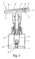
- einen schematischen Schnitt einer vorschlagsgemäßen Abgabevorrichtung gemäß einer zweiten Ausführungsform; und
- Fig. 4
- einen vergrößerten Ausschnitt von
Fig. 3 . mit geöffnetem Auslaßventil. - In den nicht maßstabsgerechten, nur schematischen Figuren werden für gleiche oder ähnliche Teile dieselben Bezugszeichen verwendet, wobei entsprechende oder vergleichbare Eigenschaften und Vorteile erreicht werden, auch wenn eine wiederholte Beschreibung weggelassen ist.
-
Fig. 1 zeigt in einem schematischen Schnitt eine vorschlagsgemäße Abgabevorrichtung 1, die hier als Abgabekopf zur Abgabe einer Flüssigkeit 2 im eingangs genannten Sinn ausgebildet ist. - Insbesondere ist die Abgabevorrichtung 1 zur nicht-sprühenden Abgabe der Flüssigkeit 2 ausgebildet. Insbesondere erfolgt eine Ausgabe der Flüssigkeit 2 als Schaum 3, vorzugsweise als Rasierschaum o.dgl., wie schematisch in
Fig. 2 angedeutet. Die Flüssigkeit 2 ist hierzu insbesondere selbst aufschäumend ausgebildet und/oder wird bei der Abgabe aufgeschäumt. - Jedoch kann die Flüssigkeit 2 grundsätzlich auch im nicht-aufgeschäumten Zustand abgegeben werden und insbesondere auch nicht-aufschäumend ausgebildet sein. Insbesondere kann auch eine Lotion als Flüssigkeit 2 ausgegeben werden. Weiter ist es auch möglich, daß die Flüssigkeit nur ganz gering aufschäumt, so daß das Aufschäumen beispielsweise lediglich das Volumen etwas vergrößert, aber im wesentlichen eine flüssige oder pastöse Konsistenz bei der Abgabe beibehalten wird.
- Die Abgabevorrichtung ist vorzugsweise mit einem Reservoir 4 für die auszugebene Flüssigkeit 2 versehen oder verbunden. Das Reservoir 4 kann also einen Teil der Abgabevorrichtung 1 bilden oder kann an diese angeschlossen sein.
- Bei der ersten Ausführungsform ist das Reservoir 4 als vorzugsweise starrer Behälter, insbesondere als Druckbehälter, ausgebildet.
- Die Flüssigkeit 2 im Reservoir 4 ist entweder unter Druck setzbar oder steht unter Druck. Insbesondere enthält der Behälter oder die Flüssigkeit 2 ein geeignetes Treibmittel, vorzugsweise ein flüchtiges und/oder brennbares Treibmittel, komprimiertes Gas und/oder Kohlendioxid.
- Bei der ersten Ausführungsform ist der Behälter insbesondere länglich und/oder zylindrisch und/oder starr - besonders bevorzugt als metallische Dose - für die Flüssigkeit 2 ausgebildet und weist besonders bevorzugt stimseitig ein Abgabeventil 5 auf, an das die Abgabevorrichtung 1 bzw. der davon gebildete Abgabekopf angeschlossen ist.
-
Fig. 2 zeigt in einer ausschnittsweisen Vergrößerung vonFig. 1 die Abgabevorrichtung 1 bzw. den davon gebildeten Abgabekopf deutlicher bei geöffnetem Auslaßventil 2 mit abgegebenem Schaum 3, aber ohne Flüssigkeit 2 im Auslaßkanal 6 - Die Abgabevorrichtung 1 weist einen auslaßkanal 6 und ein zugeordnetes Auslaßventil 7 auf. Der Auslaßkanal 6 weist eine sich vorzugsweise ins Freie öffnende bzw. stromab angeordnete Auslaßöffnung 8 auf. Mit dem Begriff "ins Freie öffnende" ist insbesondere gemeint, daß sich keine Düse, kein weiterer Kanal o.dgl. anschließt. Vielmehr kann die Flüssigkeit 2 nach Austritt aus der Auslaßöffnung 8 von einem nicht dargestellten Benutzer vorzugsweise unmittelbar aufgenommen bzw. benutzt werden.
- Das Auslaßventil 7 ist vorzugsweise der Auslaßöffnung 8 zugeordnet, so daß diese vom Auslaßventil 7 verschließbar ist.
- Das Auslaßventil 7 weist einen Ventilkörper 9 auf, der in Abhängigkeit vom anstehenden Flüssigkeitsdruck bewegbar ist, so daß das Auslaßventil 7 bei Überschreiten eines Mindestdrucks, insbesondere ausschließlich durch den Flüssigkeitsdruck öffnet.
- Besonders bevorzugt ist dieser Mindestdruck höher als ein Aufschäumdruck der selbstaufschäumenden Flüssigkeit 2. Hingegen ist dann der Abgabedruck (bei geöffneten Abgabeventil 5) und damit der anstehende Flüssigkeitsdruck wiederum höher als der Mindestdruck, so daß zur gewünschten Flüssigkeitsabgabe und Erzeugung bzw. Ausgabe des Schaums 3 dann das Auslaßventil 7 öffnet.
- Bei der ersten Ausführungsform erfolgt das Öffnen des Abgabeventils 5 vorzugsweise durch Niederdrücken der Abgabevorrichtung 1 bzw. des davon gebildeten Abgabekopfs. Das Abgabeventil 5 schließt bei Loslassen dann wieder selbstständig. Jedoch kann es sich bei dem Abgabeventil 5 beispielsweise auch um ein Dosierventil o.dgl. handeln.
- Der Ventilkörper 9 ist im wesentlichen zylindrisch ausgebildet, wie insbesondere in
Fig. 2 angedeutet. Der Ventilkörper 9 weist vorzugsweise einen Ringwulst oder insbesondere im wesentlichen konischen Dichtabschnitt 10 auf, der bei geschlossenem Auslaßventil 7 dichtend mit einem Ventilsitz 11 des Auslaßventils 7, der insbesondere von der Auslaßöffnung 8 gebildet oder unmittelbar benachbart dazu angeordnet ist, zusammenwirkt. Bedarfsweise kann der Ventilsitz 11 auch von einem sich an die Auslaßöffnung 8 anschließenden Abschnitt 12 des Auslaßkanals 6 gebildet sein. - Beim Darstellungsbeispiel weist die Abgabevorrichtung 1 bzw. der Auslaßkanal 6 vorzugsweise einen den Ventilkörper 9 umgebenden Ringkanal 13 auf, an den sich der im Querschnitt verjüngte bzw. verringerte Auslaßkanalabschnitt 12 mit der Auslaßöffnung 8 anschließt.
- Der Ventilkörper 9 besteht vorzugsweise aus elastischem Material, besonders bevorzugt einem Elastomer bzw. Polymer. Beim Darstellungsbeispiel ist der Ventilkörper 9 spritzgegossen.
- Beim Darstellungsbeispiel ist der Ventilkörper 9 vorzugsweise über einen elastisch verformbaren ringartigen Halteabschnitt 14 insbesondere axial beweglich gehalten. Besonders bevorzugt ist der Ventilkörper 9 einstückig mit dem Halteabschnitt 14 ausgebildet oder an diesen angeformt.
- Der Ventilkörper 9 ist über den Halteabschnitt 14 und/oder einen Befestigungsabschnitt 15 gehalten. Beim Darstellungsbeispiel schließt sich der Befestigungsabschnitt 15 an den vorzugsweise in seiner Dicke verringerten Halteabschnitt 14 an und/oder umgibt diesen. Besonders bevorzugt ist der Befestigungsabschnitt 15 an der Abgabevorrichtung 1 befestigt, insbesondere mit einem Bauteil 16, wie einem Oberteil, der Abgabevorrichtung 1 fest verbunden. Der Befestigungsabschnitt 15 ist an die Abgabevorrichtung 1 bzw. dessen Bauteil 16 angespritzt oder angeformt. Besonders bevorzugt erfolgt eine sog. "Bi-Injection", also insbesondere ein Anspritzen eines weiteren Materials in der gleichen Spritzform, in der ein erstes Material geformt wird.
- Beim Darstellungsbeispiel sind der Befestigungsabschnitt 15, der Halteabschnitt 14 und der Ventilkörper 9 insbesondere einstückig ausgebildet und/oder aus dem gleichen, vorzugsweise elastischem Material, insbesondere Kunststoff, besonders bevorzugt durch die genannte "Bi-Injection", hergestellt. Jedoch gibt es hier auch andere konstruktive und/oder herstellungstechnische Lösungen.
- Die Abgabevorrichtung 1 weist beim Darstellungsbeispiel ein Unterteil 17 auf, das mit dem Reservoir 4 bzw. Abgabeventil 5 verbunden oder verbindbar ist und/oder das den Auslaßkanal 6 (ggf. zusammen mit dem Bauteil 16 bzw. Befestigungsabschnitt 15), die Auslaßöffnung 8 und/oder den Ventilsitz 11 bildet. Beim Darstellungsbeispiel ist das ein Oberteil bildende Bauteil 16 mit dem Unterteil 17 so verbindbar bzw. verbunden, daß der Auslaßkanal 6 insbesondere dicht - vorzugsweise gas- bzw. luftdicht - abgedeckt bzw. abgeschlossen wird. Zusammen mit dem vorzugsweise luftdichtschließenden Auslaßventil 7 hat dies den Vorteil, daß nach der ersten Benutzung der Abgabevorrichtung 1 im Auslaßkanal 6 verbleibende Flüssigkeit 2 - auch bei längerer Lagerung bzw. Nichtbenutzung der Abgabevorrichtung 1 - nicht oder vorzugsweise zumindest nur in einem zu vernachlässigendem Maße der Einwirkung von Luft oder sonstigen äußeren Einflüssen ausgesetzt ist. Insbesondere kann so verhindert werden, daß beispielsweise eine selbsttätig aufschäumende Flüssigkeit 2, wie üblicherweise für Rasierschaum eingesetzt, im Auslaßkanal 6 aufschäumt und in unerwünschter Weise aus der Abgabevorrichtung 1 - insbesondere über längere Zeit hinweg - austritt bzw. herausquillt.
- Zur Benutzung wird die Abgabevorrichtung 1 bzw. der vorzugsweise davon gebildete Abgabekopf - vorzugsweise unmittelbar und/oder manuell - niedergedrückt oder in ansonstiger Weise betätigt, so daß das Abgabeventil 5 öffnet. Die im Reservoir bzw. Behälter 4 vorzugsweise unter Druck stehende Flüssigkeit 2 kann dann insbesondere über eine Steigleitung 18 und das geöffnete Abgabeventil 5 in den Auslaßkanal 6 strömen. Aufgrund des dann im Auslaßkanal 6 herrschenden bzw. anstehenden Flüssigkeitsdrucks bzw. Abgabedrucks öffnet das Auslaßventil 7. Bei der ersten Ausführungsform erfolgt dies dadurch, daß sich der Ventilkörper 9 aus der Auslaßöffnung 8 heraus bzw. nach außen bewegt, wobei der Halteabschnitt 14 entsprechend elastisch verformt wird. Die Flüssigkeit 2 kann dann durch das geöffnete Auslaßventil 7 bzw. die Auslaßöffnung 8 nach außen bzw. in Freie entweichen und besonders bevorzugt aufschäumen und den Schaum 3 bilden.
Fig. 2 zeigt die Abgabevorrichtung 1 bei geöffnetem Auslaßventil 7 mit dem vorzugsweise von der abgegebenen Flüssigkeit 2 gebildeten Schaum 3 im Bereich der Auslaßöffnung 8. Die abgegebene Flüssigkeit 2 bzw. der Schaum 3 kann dann von einem nicht dargestellten Benutzer insbesondere manuell abgenommen, insbesondere abgestreift oder abgewischt, werden. - Die Flüssigkeitsabgabe endet, wenn der im Auslaßkanal 6 herrschende Flüssigkeitsdruck bzw. der Abgabedruck wieder unter den Mindestdruck fällt, so daß das Auslaßventil 7 schließt. Dies ist dann der Fall, wenn das Abgabeventil 5 - insbesondere durch Loslassen bzw. automatische Rückstellung des Abgabekopfs - wieder schließt. Das geschlossene bzw. sich schließende Auslaßventil 7 verhindert dann, daß noch im Auslaßkanal 6 befindliche Flüssigkeit 2 in unerwünschter Weise aus der Auslaßöffnung 8 nachträglich austritt bzw. herausschäumt.
- Beim Darstellungsbeispiel erfolgt das Schließen des Auslaßventils 7 vorzugsweise ausschließlich durch elastische Rückstellkräfte des Halteabschnitts 14. Zusätzlich oder alternativ kann zum Schließen des Auslaßventils 7 dem Ventilkörper 9 auch eine nicht dargestellte Rückstell- oder Schließfeder zugeordnet sein.
- Um das Schließen des Auslaßventils 7 zu begünstigen, kann eine gewisse Druckkompensation vorgesehen sein. Beim Darstellungsbeispiel wirkt der im Ringkanal 13 anstehende Flüssigkeitsdruck auf den Halteabschnitt 14 in Schließrichtung. Die Druckkompensation, die Rückstellkräfte und das Schließverhalten des Auslaßventils 7 hängen insbesondere von den Flächenverhältnissen (der Fläche des Halteabschnitts 14 zu dem Querschnitt des Ventilkörpers 9 im Bereich der Anlage am Ventilsitz 11) und von der Dimensionierung und Eigenschaft des Halteabschnitts 14 ab.
- Ein besonderer Vorteil der vorschlagsgemäßen Lösung liegt darin, daß neben der Vermeidung eines nachträglichen Austretens von Flüssigkeit 2, insbesondere eines Nachschäumens, auch für den Benutzer eine sehr einfache Reinigung ermöglicht wird, da das Auslaßventil 7 vorzugsweise unmittelbar die Auslaßöffnung 8 verschließt, so daß im geschlossenen Zustand ein sauberer bzw. leicht zu reinigender Abschluß bzw. Flüssigkeitsauslaß gebildet wird.
- Beim Darstellungsbeispiel erfolgt die Flüssigkeitsausgabe im wesentlichen entgegengesetzt zur Niederdrückrichtung bzw. Öffnungsrichtung des Abgabeventils 5 und/oder zumindest im wesentlichen nach unten bzw. in Längsrichtung oder Achsrichtung des besonders bevorzugt im wesentlichen zylindrischen Reservoirs oder Behälters 4. Jedoch kann die Ausgaberichtung grundsätzlich in jede Richtung, insbesondere auch im wesentlichen horizontal und/oder seitlich bzw. radial erfolgen.
- Ein weiterer Aspekt des Darstellungsbeispiels liegt darin, daß der Ventilkörper 9 vorzugsweise in oder entgegengesetzt zu der Ausgaberichtung der Flüssigkeit 2 und/oder in der Auslaßöffnung 8 bewegbar ist.
- Weiter ist zu erwähnen, daß sich an die Auslaßöffnung 8 vorzugsweise keine weitere die flüssigkeitsabgabeformende Einrichtung, wie eine Düse, ein Kanal o.dgl. anschließt. Dies schließt jedoch nicht aus, daß beispielsweise eine schalenartige Erweiterung, gehäuseseitige Vertiefung o.dgl., in die die Auslaßöffnung 8 mündet, vorgesehen sein kann.
- Es ist anzumerken, daß anstelle der beispielhaft dargestellten Abgabe der Flüssigkeit 2 als Schaum 3 grundsätzlich auch jede sonstige Abgabe der Flüssigkeit 2 - ggf. auch als pastöze Masse, als Gel, als Tropfen oder auch als Strahl oder Sprühnebel in Frage kommt.
- Nachfolgend wird eine weitere Ausführungsform anhand der
Fig. 3 und4 näher erläutert, die zuFig. 1 und2 korrespondieren, wobei lediglich auf wesentliche Unterschiede gegenüber der ersten Ausführungsform eingegangen wird. Die bisherigen Ausführungen und Erläuterungen gelten daher insbesondere ergänzend oder entsprechend. - Bei der zweiten Ausführungsform schäumt die Flüssigkeit 2 nicht bzw. wird nicht aufgeschäumt.
- Bei der zweiten Ausführungsform ist die Abgabevorrichtung 1 mit einer vorzugsweise manuell betätigbaren Pumpe 19, insbesondere einer Dosier- bzw. Spenderpumpe, versehen oder daran angeschlossen. Durch Niederdrücken des von der Abgabevorrichtung 1 gebildeten Abgabekopfs wird die Flüssigkeit 2 in den Dosierkanal 6 gefördert und ein derartiger Abgabedruck erzeugt, daß das Auslaßventil 7 öffnet und die Flüssigkeit 2 über die Auslaßöffnung 8 abgegeben wird. Bei Loslassen des Abgabekopfs erfolgt ein vorzugsweise selbsttätiges Zurückstellen, wobei während der Rückstellbewegung das Abgabeventil 5 der Pumpe 19 schließt und ein Einlaßventil 20 öffnet, um neue Flüssigkeit 2 aus dem Reservoir 5 in eine Pumpenkammer 21 der Pumpe 19 zu saugen.
- Bei der zweiten Ausführungsform verhindert das Auslaßventil 7 insbesondere ein unerwünschtes Nachtropfen von Flüssigkeit 2 aus dem Auslaßkanal 6 bzw. aus der Auslaßöffnung 8.
- Bei der zweiten Ausführungsform ist das Auslaßventil 7 derart ausgebildet, daß sich zum Öffnen der Ventilkörper 9 in die Auslaßöffnung 8 bzw. den sich stromauf anschließenden Abschnitt 12 des Auslaßkanals 6 zurückbewegt. wie in
Fig. 4 angedeutet. Insbesondere ist hier eine im wesentlichen radiale Dichtung bei geschlossenem Auslaßventil 7 zwischen dem Ventilkörper 9 bzw. dessen Ringwulst oder Dichtabschnitt 10 einerseits und dem Auslaßkanalabschnitt 12 bzw. Ventilsitz 11 andererseits gebildet (sieheFig. 3 ). - Der Ventilkörper 9 endet - insbesondere bei geschlossenem Auslaßventil 7-zumindest im wesentlichen in der Ebene der Auslaßöffnung 8. Dies gilt insbesondere auch für die erste Ausführungsform.
- Alternativ kann der Ventilkörper 9 auch über die Auslaßöffnung 8 nach außen vorragen, dies gilt insbesondere bei der ersten Ausführungsform, besonders bevorzugt bei geöffnetem Auslaßventil 7, ggf. aber auch bei geschlossenem Auslaßventil 7.
- Einzelne Merkmale und Aspekte der verschiedenen Ausführungsformen können beliebig miteinander kombiniert oder bei sonstigen Abgabevorrichtungen o. dgl. eingesetzt werden.
-
- 1
- Abgabevorrichtung
- 2
- Flüssigkeit
- 3
- Schaum
- 4
- Reservoir
- 5
- Abgabeventil
- 6
- Auslaßkanal
- 7
- Auslaßventil
- 8
- Auslaßöffnung
- 9
- Ventilkörper
- 10
- Dichtabschnitt
- 11
- Ventilsitz
- 12
- Auslaßkanalabschnitt
- 13
- Ringkanal
- 14
- Halteabschnitt
- 15
- Befestigungsabschnitt
- 16
- Bauteil
- 17
- Unterteil
- 18
- Steigleitung
- 19
- Pumpe
- 20
- Einlaßventil
- 21
- Pumpenkammer
Claims (15)
- Abgabevorrichtung (1) zur nicht-sprühenden Abgabe einer vorzugsweise kosmetischen Flüssigkeit (2), mit einem Auslasskanal (6) und einem zugeordneten Auslassventil (7), wobei der Auslasskanal (6) eine stromab angeordnete Auslassöffnung (8) aufweist, die vom Auslassventil (7) verschließbar ist, wobei das Auslassventil (7) einen Ventilkörper (9) aufweist, der in Abhängigkeit vom anstehenden Flüssigkeitsdruck bewegbar ist, so dass das Auslassventil (7) bei Überschreiten eines Mindestdrucks öffnen kann, wobei der Ventilkörper (9) im Wesentlichen zylindrisch ausgebildet ist, wobei der Ventilkörper (9) über einen elastisch verformbaren, ringartigen Halteabschnitt (14) gehalten ist, und wobei sich ein Befestigungsabschnitt (15) an den Halteabschnitt (14) anschließt,
dadurch gekennzeichnet,
dass der Befestigungsabschnitt (15) an ein Bauteil (16) der Abgabevorrichtung (1) angespritzt ist, und dass das Auslassventil (7) ausschließlich durch elastische Rückstellkräfte des Halteabschnitts (14) schließbar ist. - Abgabevorrichtung nach Anspruch 1, dadurch gekennzeichnet, dass die Abgabevorrichtung (1) als Abgabekopf ausgebildet ist oder einen solchen aufweist, und/oder dass die Abgabevorrichtung (1) an eine Pumpe (19) zur Förderung der Flüssigkeit (2) angeschlossen oder anschtießbar oder damit versehen ist, wobei die Pumpe (19) durch Niederdrücken betätigbar ist.
- Abgabevorrichtung nach Anspruch 1 oder 2, dadurch gekennzeichnet, dass die Abgabevorrichtung (1) an ein Reservoir (4), insbesondere einen unter Druck stehenden oder setzbaren Behälter, mit der Flüssigkeit (2) angeschlossen oder anschließbar oder damit versehen ist, und/oder dass die Abgabevorrichtung (1) an ein Abgabeventil (5) angeschlossen ist, das durch Niederdrücken öffenbar ist.
- Abgabevorrichtung nach einem der voranstehenden Ansprüche, dadurch gekennzeichnet, dass die Flüssigkeit (2) als Schaum (3) abgebbar ist.
- Abgabevorrichtung nach einem der voranstehenden Ansprüche, dadurch gekennzeichnet, dass der Mindestdruck des Auslassventils (7) höher als ein Aufschäumdruck der selbst aufschäumenden Flüssigkeit (2) ist, und/oder dass das Auslassventil (7) luftdicht und/oder tropffrei schließbar ist.
- Abgabevorrichtung nach einem der voranstehenden Ansprüche, dadurch gekennzeichnet, dass die Abgabevorrichtung (1) ein Oberteil mit einem Ventilelement (9) des Auslassventil (7) aufweist, wobei das Oberteil einstückig ausgebildet und/oder durch Bi-Injektion hergestellt ist, und/oder dass die Auslassöffnung oder ein sich daran anschließender Abschnitt (12) des Auslasskanals (6) einen Ventilsitz (11) des Auslassventils (7) bzw. für den Ventilkörper (9) bildet.
- Abgabevorrichtung nach einem der voranstehenden Ansprüche, dadurch gekennzeichnet, dass der Ventilkörper (9) bei geschlossenem Auslassventil (7) zumindest im Wesentlichen in der Ebene der Auslassöffnung (8) endet, oder dass der Ventilkörper (9) über die Auslassöffnung (8) nach außen vorragt.
- Abgabevorrichtung nach einem der voranstehenden Ansprüche, dadurch gekennzeichnet, dass der Ventilkörper (9) einen bei geschlossenem Auslassventil (7) dichtend mit einem Ventilsitz (11) des Auslassventils (7) zusammenwirkenden Ringwulst oder einen im Wesentlichen konischen, bei geschlossenem Auslassventil (7) dichtend mit einem Ventilsitz (11) des Auslassventils (7) zusammenwirkenden Dichtabschnitt (10) aufweist.
- Abgabevorrichtung nach einem der voranstehenden Ansprüche, dadurch gekennzeichnet, dass der Ventilkörper (9) aus elastischem Material besteht, und/oder dass der Ventilkörper (9) spritzgegossen ist.
- Abgabevorrichtung nach einem der voranstehenden Ansprüche, dadurch gekennzeichnet, dass der Ventilkörper (9) einstückig mit dem Halteabschnitt (14) ausgebildet oder an diesen angeformt ist.
- Abgabevorrichtung nach einem der voranstehenden Ansprüche, dadurch gekennzeichnet, dass die Auslassöffnung (8) sich ins freie öffnet.
- Abgabevorrichtung nach einem der voranstehenden Ansprüche, dadurch gekennzeichnet, dass der Ventilkörper (9) zum Öffnen des Auslassventils (7) in die Auslassöffnung (8) bzw. ein sich stromauf anschließender Abschnitt des Auslasskanals (6) zurückbewegbar ist.
- Abgabevorrichtung nach einem der Ansprüche 1 bis 11, dadurch gekennzeichnet, dass der Ventilkörper (9) zum Öffnen des Auslassventils (7) aus der Auslassöffnung (8) heraus oder nach außen bewegbar ist.
- Abgabevorrichtung nach einem der voranstehenden Ansprüche, dadurch gekennzeichnet, dass der Befestigungsabschnitt (15), der Halteabschnitt (14) und der Ventilkörper (9) einstückig ausgebild sind.
- Abgabevorrichtung nach einem der voranstehenden Ansprüche, dadurch gekennzeichnet, dass der Befestigungsabschnitt (15) den in seiner Dicke verringertem Halteabschnitt (14) umgibt.
Applications Claiming Priority (2)
| Application Number | Priority Date | Filing Date | Title |
|---|---|---|---|
| DE102006042482 | 2006-09-07 | ||
| PCT/EP2007/007694 WO2008028619A1 (de) | 2006-09-07 | 2007-09-04 | Abgabevorrichtung |
Publications (2)
| Publication Number | Publication Date |
|---|---|
| EP2099572A1 EP2099572A1 (de) | 2009-09-16 |
| EP2099572B1 true EP2099572B1 (de) | 2014-07-23 |
Family
ID=38690686
Family Applications (1)
| Application Number | Title | Priority Date | Filing Date |
|---|---|---|---|
| EP07818047.8A Active EP2099572B1 (de) | 2006-09-07 | 2007-09-04 | Abgabevorrichtung |
Country Status (5)
| Country | Link |
|---|---|
| US (1) | US8261952B2 (de) |
| EP (1) | EP2099572B1 (de) |
| DE (1) | DE202007012331U1 (de) |
| ES (1) | ES2517868T3 (de) |
| WO (1) | WO2008028619A1 (de) |
Families Citing this family (17)
| Publication number | Priority date | Publication date | Assignee | Title |
|---|---|---|---|---|
| DE102005025371A1 (de) * | 2005-05-31 | 2006-12-07 | Seaquist Perfect Dispensing Gmbh | Vorrichtung zur Ausgabe eines vorzugsweise kosmetischen Fluids |
| DE102006012302A1 (de) * | 2006-03-15 | 2007-09-27 | Seaquist Perfect Dispensing Gmbh | Abgabevorrichtung |
| DE102006030741A1 (de) * | 2006-04-04 | 2007-10-11 | Seaquist Perfect Dispensing Gmbh | Dosierventil und Vorrichtung zur Abgabe einer vorzugsweise kosmetischen Flüssigkeit |
| DE102006030829B4 (de) * | 2006-05-12 | 2019-10-24 | Aptar Dortmund Gmbh | Abgabevorrichtung und Verfahren zu dessen Herstellung |
| ES2603415T3 (es) * | 2006-05-16 | 2017-02-27 | Aptar Dortmund Gmbh | Dispositivo expendedor |
| DE102006027042A1 (de) * | 2006-06-08 | 2007-12-13 | Seaquist Perfect Dispensing Gmbh | Abgabevorrichtung |
| DE102007049614B4 (de) * | 2007-03-15 | 2015-03-05 | Aptar Dortmund Gmbh | Abgabevorrichtung |
| DE102007051980A1 (de) * | 2007-08-29 | 2009-03-05 | Seaquist Perfect Dispensing Gmbh | Abgabevorrichtung |
| ES2436002T3 (es) * | 2008-06-20 | 2013-12-26 | Aptar Dortmund Gmbh | Dispositivo de distribución |
| FR2933082B1 (fr) * | 2008-06-27 | 2012-12-28 | Seaquist Perfect Dispensing Sas | Tete de distribution de produit fluide |
| DE102008038654B4 (de) | 2008-08-12 | 2019-09-19 | Aptar Dortmund Gmbh | Abgabekopf mit schwenkbarem Ventilelement |
| US8286839B2 (en) * | 2008-08-12 | 2012-10-16 | Aptar Dortmund Gmbh | Dispensing device |
| DE102009030627B4 (de) | 2009-06-25 | 2020-03-12 | Aptar Dortmund Gmbh | Ventil und Abgabevorrichtung |
| JP5674138B2 (ja) * | 2011-01-31 | 2015-02-25 | 株式会社吉野工業所 | 泡吐出器 |
| DE102012016605A1 (de) | 2012-07-06 | 2014-01-09 | Aptar Dortmund Gmbh | Abgabekopf und Abgabevorrichtung |
| EP3513880B1 (de) * | 2018-01-23 | 2021-08-25 | The Procter & Gamble Company | Abgabevorrichtung, die für schäumende produkte geeignet ist |
| EP4353624A4 (de) | 2021-06-07 | 2025-05-14 | Eric Zembrod | Retentionsventil für eine reihe von verpackungen |
Family Cites Families (134)
| Publication number | Priority date | Publication date | Assignee | Title |
|---|---|---|---|---|
| US3104785A (en) | 1963-09-24 | Metering valve for pressure packages | ||
| US2736930A (en) | 1953-10-28 | 1956-03-06 | John D Longley | Door frame |
| BE535408A (de) | 1954-08-16 | |||
| NL95166C (de) | 1954-09-20 | |||
| US2884164A (en) | 1957-03-08 | 1959-04-28 | Arnold Copeland Co Inc | Fluid dispenser |
| US2837249A (en) | 1957-05-10 | 1958-06-03 | Meshberg Philip | Aerosol valve |
| US2980301A (en) | 1958-09-02 | 1961-04-18 | Riker Laboratories Inc | Metering valve for aerosol container |
| US3018928A (en) | 1958-11-24 | 1962-01-30 | Meshberg Philip | Metering valve |
| US3003662A (en) | 1959-09-14 | 1961-10-10 | Meshberg Philip | Device and method for dispensing material under pressure of an immiscible gas |
| US3073489A (en) | 1960-06-06 | 1963-01-15 | Jack N Friedman | Aerosol metering valve assembly |
| US3131834A (en) | 1961-08-23 | 1964-05-05 | Meshberg Philip | Device and method for dispensing material under pressure of a propellent immiscible gs |
| US3258369A (en) | 1962-11-29 | 1966-06-28 | Bosch Gmbh Robert | Fluid-tightly closed devices, such as storage batteries or the like, and method for manufacturing the same |
| US3385482A (en) | 1966-07-11 | 1968-05-28 | Revlon | Metered valve |
| US3507586A (en) | 1968-04-04 | 1970-04-21 | Erich W Gronemeyer | Pump |
| US3542253A (en) | 1968-06-19 | 1970-11-24 | Robert L Weber | Low force aerosol valve with metering cap |
| US3511418A (en) | 1968-07-29 | 1970-05-12 | Risdon Mfg Co | Variable capacity aerosol metering valve |
| US3608830A (en) | 1969-07-15 | 1971-09-28 | Mario A Ramella | Spray head and valve for pressurized container |
| US3698961A (en) | 1970-01-29 | 1972-10-17 | Bosch Gmbh Robert | Sealed battery with synthetic resin case and cover |
| GB1327800A (en) | 1970-08-28 | 1973-08-22 | Idees Soc Civ | Pressurized measuring dispenser |
| US3672543A (en) | 1971-02-11 | 1972-06-27 | Plant Ind Inc | Flowable substances dispenser |
| US3726442A (en) | 1971-02-17 | 1973-04-10 | Polypump Curacao Nv | Trigger pump and breather valve dispensing assembly |
| FR2127774A5 (de) | 1971-02-26 | 1972-10-13 | Polypump Curacao Nv | |
| US3706393A (en) | 1971-07-12 | 1972-12-19 | Pelorex Corp | Plastic container and method of making the same |
| US3796356A (en) | 1972-04-12 | 1974-03-12 | Plant Ind Inc | Telescoping mandrel for expansible bladder container |
| DE7231412U (de) | 1972-08-25 | 1972-11-23 | R Dietsche Kg | Drahtmassagebuerste |
| US3795350A (en) | 1972-10-16 | 1974-03-05 | Scovill Manufacturing Co | Aerosol valve having selectable flow rate |
| US3961725A (en) | 1974-04-09 | 1976-06-08 | Clark Richard A | Method and apparatus for dispensing fluids under pressure |
| US3931831A (en) | 1974-05-02 | 1976-01-13 | French George F | Elastic check valve and method of construction |
| US3991916A (en) | 1974-07-01 | 1976-11-16 | Bon F Del | Automatic closure device for the discharge of a foam product from a pressurized container |
| CH591998A5 (de) | 1974-12-20 | 1977-10-14 | Green Edward Howard | |
| US4099651A (en) | 1975-05-22 | 1978-07-11 | Von Winckelmann Emil H | Closure assembly for collapsible tube dispensers, and the like |
| US4035303A (en) | 1976-01-16 | 1977-07-12 | Seaquist Valve Company | Open mesh filter element |
| US4222501A (en) | 1978-07-24 | 1980-09-16 | James D. Pauls And J. Claybrook Lewis And Associates, Limited | Dual chamber, continuous action dispenser |
| DE2920497C2 (de) | 1979-05-21 | 1983-03-10 | Rhen Beteiligungs- und Finanzierungs-AG, Stein am Rhein | Dosierventil |
| US4304749A (en) | 1980-02-22 | 1981-12-08 | Peter Bauer | Method for mass production assembly of fluidic devices |
| US4352443A (en) | 1980-06-24 | 1982-10-05 | U.S. Cap & Closure, Inc. | Dispenser having a trigger-bulb pump |
| US4423829A (en) | 1980-08-28 | 1984-01-03 | Container Industries Inc. | Apparatus for containing and dispensing fluids under pressure and method of manufacturing same |
| ATE39668T1 (de) | 1980-08-28 | 1989-01-15 | Hyman Katz | Vorrichtung zur aufnahme und aufgabe von unter druck stehenden fluessigen medien und verfahren zu ihrer herstellung. |
| DE3033392A1 (de) | 1980-09-05 | 1982-04-29 | Pfeiffer Kunststofftechnik GmbH & Co KG, 7760 Radolfzell | Vorrichtung zur ausgabe von pasteusen oder breiigen medien |
| DE3037252C2 (de) | 1980-10-02 | 1983-12-29 | Wilhelm Rogg Kunststoff-Metallisierung, 8500 Nürnberg | Spritzgießform zum Herstellen von Formkörpern aus zwei Kunststoffarten |
| US4387833A (en) | 1980-12-16 | 1983-06-14 | Container Industries, Inc. | Apparatus for containing and dispensing fluids under pressure and method of producing same |
| FR2510069A1 (fr) | 1981-07-21 | 1983-01-28 | Blanie Paul | Dispositif de distribution de liquides et pates |
| GB2105729B (en) | 1981-09-15 | 1985-06-12 | Itt Ind Ltd | Surface processing of a substrate material |
| US4496082A (en) * | 1981-12-18 | 1985-01-29 | Corsette Douglas Frank | Liquid dispensing pump |
| DE3224199A1 (de) | 1982-06-29 | 1983-12-29 | Josef Wischerath GmbH & Co, 5000 Köln | Spender fuer pastoese produkte |
| SE8305995L (sv) | 1983-11-01 | 1985-05-02 | Kebo Production | Anordning for utmatning av en vetske- eller kramformig produkt ur en behallare, innehallande en dylik produkt |
| GB2155435B (en) | 1984-03-06 | 1988-05-25 | Brightwell Dispensers | Dispenser for liquid soap |
| FR2566746B1 (fr) | 1984-06-29 | 1986-10-31 | Aerosol Inventions Dev | Dispositif pour deposer un ruban lateral de substance pateuse sur un cordon de pate. |
| DE3601311A1 (de) | 1986-01-17 | 1987-07-23 | Joachim Czech | Spender fuer pastoese produkte |
| EP0258299B1 (de) | 1986-01-30 | 1990-05-16 | Bespak plc | Dosierventil mit verformbarer kammer |
| GB8617350D0 (en) | 1986-07-16 | 1986-08-20 | Metal Box Plc | Pump chamber dispenser |
| GB8629982D0 (en) | 1986-12-16 | 1987-01-28 | English Glass Co Ltd | Dispenser pump |
| DE3886184D1 (de) | 1987-06-26 | 1994-01-20 | Werding Winfried J | Vorrichtung zur lagerung und kontrollierten abgabe von unter druck stehenden produkten und verfahren zu ihrer herstellung. |
| US5221724A (en) | 1987-08-12 | 1993-06-22 | Wisconsin Alumni Research Foundation | Polysiloxane polyurea urethanes |
| JP2701401B2 (ja) | 1988-12-29 | 1998-01-21 | ソニー株式会社 | カセットリール |
| EP0549050B1 (de) | 1989-07-25 | 1996-01-03 | L'oreal | Abgabevorrichtung für wenigstens ein flüssiges Produkt, insbesondere kosmetischer oder pharmazeutischer Art |
| FR2654079B1 (fr) | 1989-11-07 | 1992-04-10 | Valois | Poussoir d'actionnement d'un distributeur de produits pateux. |
| DK0442858T3 (da) | 1990-02-16 | 1994-09-19 | Sterisol Ab | Ventil til portionsvis afgivelse af en væske |
| DE59104114D1 (de) | 1990-04-09 | 1995-02-16 | Lir France Sa | Pumpvorrichtung für ein fliessfähiges, insbesondere pastöses und/oder flüssiges Produkt und Spender mit einer solchen Pumpvorrichtung. |
| US5007556A (en) | 1990-04-18 | 1991-04-16 | Block Drug Company, Inc. | Metering dispenser |
| DE4210225A1 (de) * | 1992-03-28 | 1993-09-30 | Katz Otto | Spender für Flüssigkeiten und Pasten |
| FR2679620B1 (fr) | 1991-07-25 | 1993-10-29 | Oreal | Valve reglable. |
| FR2693991B1 (fr) | 1992-07-21 | 1994-11-25 | Oreal | Ensemble de distribution d'au moins un produit liquide ou pâteux, comportant un système de fermeture sans reprise d'air et procédé de conservation utilisant ledit ensemble. |
| US5487494A (en) | 1992-11-19 | 1996-01-30 | Robbins, Iii; Edward S. | Dispensing cap with internal measuring chamber and selectively useable sifter |
| US5454488A (en) | 1992-11-24 | 1995-10-03 | Coster Technologie Speciali Spa Stabilimento Di Calceranica | Apparatus for dispensing a semifluid medium from a container |
| US6152335A (en) | 1993-03-12 | 2000-11-28 | Homax Products, Inc. | Aerosol spray texture apparatus for a particulate containing material |
| FR2704458B1 (fr) | 1993-04-28 | 1995-07-21 | Oreal | Ensemble de distribution de produit. |
| DE9307083U1 (de) | 1993-05-11 | 1993-07-22 | Linneweber, Wolfgang, 4800 Bielefeld | Selbstschließender Verschluß |
| FR2711554B1 (fr) | 1993-10-22 | 1995-12-22 | Oreal | Ensemble de distribution à reprise d'air commandée. |
| FR2711555B1 (fr) | 1993-10-22 | 1996-01-26 | Oreal | Ensemble de distribution à chambre de compression à volume variable à membrane. |
| FR2717447B1 (fr) * | 1994-03-21 | 1996-05-31 | Labcatal | Dispositif doseur destiné à délivrer des doses unitaires constantes. |
| DE69425065T2 (de) | 1994-08-29 | 2001-03-08 | Osaka Shipbuilding Co., Ltd. | Aerosolbehälter mit einer konstanten abgabe |
| US6112953A (en) | 1994-10-20 | 2000-09-05 | L'oreal | Dispensing assembly equipped with a unidirectional closure member |
| WO1996019389A1 (en) | 1994-12-22 | 1996-06-27 | Pentel Kabushiki Kaisha | Discharge container |
| US5732855A (en) * | 1995-03-06 | 1998-03-31 | Park Towers International B.V. | Spray head intended for a spray can, and spray can provided with such a spray head |
| FR2736623B1 (fr) | 1995-07-10 | 1997-08-22 | Oreal | Dispositif de conditionnement et de distribution d'un produit liquide, gelifie ou pateux avec applicateur en forme de dome |
| FR2742128B1 (fr) | 1995-12-08 | 1998-01-16 | Oreal | Tete de distribution equipee d'un systeme de fermeture a reprise d'air |
| US5728333A (en) | 1995-12-25 | 1998-03-17 | Bridgestone Corporation | Method for making and then removing a molded article of rigid polyurethane foam from a mold |
| US5875936A (en) | 1996-01-22 | 1999-03-02 | Chesebrough-Pond's Usa Co., Division Of Conopco, Inc. | Refillable pump dispenser and refill cartridge |
| DE19612702A1 (de) | 1996-03-29 | 1997-10-02 | Coster Tecnologie Speciali Spa | Ventil für die Abgabe von unter Druck stehenden Fluiden |
| IT1282759B1 (it) | 1996-05-29 | 1998-03-31 | Ter Srl | Distributore di sostanze cremose |
| FR2752561B1 (fr) | 1996-08-22 | 1998-09-18 | Oreal | Capsule de distribution pour un produit liquide equipee d'un bouchon, et procede de fabrication de cette capsule |
| WO1998014279A1 (en) * | 1996-10-03 | 1998-04-09 | Pentel Kabushiki Kaisha | Blow-out container |
| US6328920B1 (en) | 1996-11-27 | 2001-12-11 | Honda Engineering North America, Inc. | Molding process for forming complex shapes |
| CA2230768C (en) | 1997-02-28 | 2007-02-13 | John W. Safian | Multilayer container package |
| US5873491A (en) | 1997-04-14 | 1999-02-23 | Valois S.A. | Set of components for assembly as a dispensing package of the non-vented type having an internal, collapsible bag |
| US5881929A (en) | 1997-04-25 | 1999-03-16 | Summit Packaging Systems, Inc. | Plastic coated mounting cup for spray button seal |
| EP0893356A1 (de) | 1997-07-23 | 1999-01-27 | The Procter & Gamble Company | Mehrlagiger, druckfester Behälter |
| AU718986B2 (en) | 1997-08-13 | 2000-05-04 | Yoshino Kogyosho Co., Ltd. | Manually operated spray device for liquid |
| US6349015B1 (en) | 1997-08-14 | 2002-02-19 | Fuji Photo Film Co., Ltd. | Magnetic tape cartridge |
| FR2769008B1 (fr) * | 1997-09-30 | 1999-11-19 | Oreal | Tete de distribution et ensemble de conditionnement et de distribution equipe d'une telle tete |
| DE19744510A1 (de) | 1997-10-09 | 1999-04-15 | Alpla Design Lehner Gmbh | Spender |
| FR2769595B1 (fr) | 1997-10-10 | 1999-11-19 | Oreal | Tete de distribution a reprise d'air amelioree, et ensemble de conditionnement et de distribution equipe d'une telle tete |
| US5857224A (en) | 1997-10-14 | 1999-01-12 | Sloan Valve Company | Pressure flush tank for use in a toilet enclosure |
| US6007914A (en) | 1997-12-01 | 1999-12-28 | 3M Innovative Properties Company | Fibers of polydiorganosiloxane polyurea copolymers |
| SE9704769D0 (sv) | 1997-12-19 | 1997-12-19 | Astra Ab | Medical device |
| FR2776540B1 (fr) | 1998-03-27 | 2000-06-02 | Sidel Sa | Recipient en matiere a effet barriere et procede et appareil pour sa fabrication |
| DE19832824C2 (de) | 1998-07-21 | 2002-05-16 | Coster Tecnologie Speciali Spa | Abgabepumpe für die Abgabe von Flüssigkeiten, Gelen oder dgl. Medien |
| DE19851659A1 (de) | 1998-11-10 | 2000-05-11 | Kertels Peter | Adapter zur Abgabe von Produkten unter sterilen Bedingungen |
| DE29820894U1 (de) | 1998-11-24 | 1999-01-21 | Georg Menshen GmbH & Co. KG, 57413 Finnentrop | Selbstschließende Ventilanordnung für eine Behälterspendeöffnung |
| US6441741B1 (en) | 1999-05-17 | 2002-08-27 | Avid Identification Systems, Inc. | Overmolded transponder |
| US6216916B1 (en) | 1999-09-16 | 2001-04-17 | Joseph S. Kanfer | Compact fluid pump |
| DE19950512B4 (de) | 1999-10-20 | 2004-02-26 | Stiebel Eltron Gmbh & Co. Kg | Durch Ultraschallschweißen verbindbare Baugruppe |
| GB2360272B (en) | 2000-03-07 | 2002-02-13 | Bespak Plc | Improvements in or relating to valves for dispensers |
| US6298960B1 (en) | 2000-05-30 | 2001-10-09 | Illinois Tool Works Inc. | Small viscous precision damper |
| JP4136299B2 (ja) | 2000-09-12 | 2008-08-20 | キヤノン株式会社 | 合成樹脂製の部品結合体 |
| US6516976B2 (en) | 2000-12-19 | 2003-02-11 | Kimberly-Clark Worldwide, Inc. | Dosing pump for liquid dispensers |
| KR200233932Y1 (ko) * | 2001-01-22 | 2001-09-25 | 강성일 | 배출 장치 및 그를 이용한 화장품 용기 |
| FR2829475B1 (fr) | 2001-09-10 | 2003-12-26 | Oreal | Valve a debit variable et recipient equipe d'une telle valve |
| DE10200593A1 (de) * | 2002-01-10 | 2003-07-31 | Aero Pump Gmbh | Betätigungskopf einer Saug-Druck-Pumpe zum Ausspritzen eines Produkts aus einem Behältnis |
| DE20203841U1 (de) * | 2002-03-09 | 2002-06-06 | Padar, Steven, 65779 Kelkheim | Abgabevorrichtung für eine flüssige medikamentöse Zusammensetzung |
| FR2838108B1 (fr) | 2002-04-03 | 2004-06-18 | Qualipac Sa | Capsule de distribution de fluide |
| US6756004B2 (en) | 2002-04-24 | 2004-06-29 | Lear Corporation | Method for manufacturing cockpit-type instrument panels |
| US6832704B2 (en) | 2002-06-17 | 2004-12-21 | Summit Packaging Systems, Inc. | Metering valve for aerosol container |
| US7913877B2 (en) | 2003-01-21 | 2011-03-29 | Aptargroup Inc. | Aerosol mounting cup for connection to a collapsible container |
| DE10308727B3 (de) | 2003-02-28 | 2004-06-09 | Krauss-Maffei Kunststofftechnik Gmbh | Verbundbauteil mit teilbeweglichen Elementen und Verfahren zu dessen Herstellung |
| FR2870525B1 (fr) * | 2004-05-19 | 2006-06-23 | Rexam Dispensing Smt Soc Par A | Dispositif pour la distribution de produits liquides sans reprise d'air |
| DE202004011220U1 (de) | 2004-06-14 | 2004-11-04 | Seaquist Perfect Dispensing Gmbh | Vorrichtung und Sprühkopf zur Zerstäubung einer vorzugsweise kosmetischen Flüssigkeit |
| DE102004034629A1 (de) | 2004-06-14 | 2006-01-05 | Seaquist Perfect Dispensing Gmbh | Vorrichtung und Sprühkopf zur Zerstäubung einer vorzugsweise kosmetischen Flüssigkeit sowie Verfahren zum Herstellen einer derartigen Vorrichtung |
| DE202004011219U1 (de) | 2004-06-17 | 2004-11-04 | Seaquist Perfect Dispensing Gmbh | Dosierventil und Vorrichtung zur Abgabe einer vorzugsweise kosmetischen Flüssigkeit |
| US7654419B2 (en) | 2004-09-17 | 2010-02-02 | Meadwestvaco Calmar, Inc. | Dispenser having elastomer discharge valve |
| US7121438B2 (en) | 2004-09-17 | 2006-10-17 | Seaquist Closures Foreign, Inc. | Multiple lid closure with open lid retention feature |
| AU2006332049A1 (en) | 2005-01-25 | 2007-08-23 | Medical Instill Technologies, Inc. | Container and closure assembly for a fat containing liquid product |
| DE102005025371A1 (de) | 2005-05-31 | 2006-12-07 | Seaquist Perfect Dispensing Gmbh | Vorrichtung zur Ausgabe eines vorzugsweise kosmetischen Fluids |
| DE102006012302A1 (de) | 2006-03-15 | 2007-09-27 | Seaquist Perfect Dispensing Gmbh | Abgabevorrichtung |
| DE102006030741A1 (de) | 2006-04-04 | 2007-10-11 | Seaquist Perfect Dispensing Gmbh | Dosierventil und Vorrichtung zur Abgabe einer vorzugsweise kosmetischen Flüssigkeit |
| DE102006030829B4 (de) | 2006-05-12 | 2019-10-24 | Aptar Dortmund Gmbh | Abgabevorrichtung und Verfahren zu dessen Herstellung |
| ES2603415T3 (es) | 2006-05-16 | 2017-02-27 | Aptar Dortmund Gmbh | Dispositivo expendedor |
| DE102006023663B4 (de) | 2006-05-16 | 2020-07-02 | Aptar Dortmund Gmbh | Abgabevorrichtung |
| US20080110941A1 (en) | 2006-11-14 | 2008-05-15 | Continentalafa Dispensing Company | Rotational Dispensing Cap Closure for a Liquid Container |
| DE102007049614B4 (de) | 2007-03-15 | 2015-03-05 | Aptar Dortmund Gmbh | Abgabevorrichtung |
| FR2914963B1 (fr) * | 2007-04-12 | 2009-07-10 | Rexam Dispensing Smt Soc Par A | Pompe de distribution d'un liquide contenu dans un flacon |
| ES2436002T3 (es) | 2008-06-20 | 2013-12-26 | Aptar Dortmund Gmbh | Dispositivo de distribución |
| US8286839B2 (en) | 2008-08-12 | 2012-10-16 | Aptar Dortmund Gmbh | Dispensing device |
-
2007
- 2007-09-04 EP EP07818047.8A patent/EP2099572B1/de active Active
- 2007-09-04 US US12/439,736 patent/US8261952B2/en active Active
- 2007-09-04 WO PCT/EP2007/007694 patent/WO2008028619A1/de not_active Ceased
- 2007-09-04 ES ES07818047.8T patent/ES2517868T3/es active Active
- 2007-09-04 DE DE202007012331U patent/DE202007012331U1/de not_active Expired - Lifetime
Also Published As
| Publication number | Publication date |
|---|---|
| DE202007012331U1 (de) | 2007-11-15 |
| ES2517868T3 (es) | 2014-11-04 |
| US20100108722A1 (en) | 2010-05-06 |
| US8261952B2 (en) | 2012-09-11 |
| EP2099572A1 (de) | 2009-09-16 |
| WO2008028619A1 (de) | 2008-03-13 |
Similar Documents
| Publication | Publication Date | Title |
|---|---|---|
| EP2099572A1 (de) | Abgabevorrichtung | |
| DE102007049614B4 (de) | Abgabevorrichtung | |
| EP2481484B1 (de) | Abgabevorrichtung | |
| DE102009030627B4 (de) | Ventil und Abgabevorrichtung | |
| EP2135822B1 (de) | Abgabevorrichtung | |
| EP1842798B1 (de) | Dosierventil und Vorrichtung zur Abgabe einer vorzugsweise kosmetischen Flüssigkeit | |
| DE1482675A1 (de) | Ausgabevorrichtung fuer fluessige Stoffe | |
| DE102008038654B4 (de) | Abgabekopf mit schwenkbarem Ventilelement | |
| DE20201742U1 (de) | Spender für fließfähige Produkte | |
| DE69903447T2 (de) | Behälterventil | |
| EP2869934B1 (de) | Abgabekopf und abgabevorrichtung | |
| EP3736049B1 (de) | Austragkopf und flüssigkeitsspender mit einem austragkopf | |
| DE2801736A1 (de) | Drucknopf-nadelschliessventil | |
| EP1765698B1 (de) | Dosierventil und vorrichtung zur abgabe einer vorzugsweise kosmetischen flüssigkeit | |
| DE602004010660T2 (de) | Verbesserungen in bezug auf austragvorrichtung | |
| DE202004011219U1 (de) | Dosierventil und Vorrichtung zur Abgabe einer vorzugsweise kosmetischen Flüssigkeit | |
| EP1514608A1 (de) | Dosiervorrichtung mit einem elastischen Betätigungsglied | |
| DE1750186A1 (de) | Abgabevorrichtung | |
| EP1160178A2 (de) | Abgabekopf für eine eine pastöse Substanz enthaltende Druckpackung | |
| DE1293093B (de) | Dosiervorrichtung |
Legal Events
| Date | Code | Title | Description |
|---|---|---|---|
| PUAI | Public reference made under article 153(3) epc to a published international application that has entered the european phase |
Free format text: ORIGINAL CODE: 0009012 |
|
| 17P | Request for examination filed |
Effective date: 20090401 |
|
| AK | Designated contracting states |
Kind code of ref document: A1 Designated state(s): AT BE BG CH CY CZ DE DK EE ES FI FR GB GR HU IE IS IT LI LT LU LV MC MT NL PL PT RO SE SI SK TR |
|
| 17Q | First examination report despatched |
Effective date: 20091008 |
|
| DAX | Request for extension of the european patent (deleted) | ||
| RAP1 | Party data changed (applicant data changed or rights of an application transferred) |
Owner name: APTAR DORTMUND GMBH |
|
| RIC1 | Information provided on ipc code assigned before grant |
Ipc: A45D 34/04 20060101ALI20131129BHEP Ipc: B05B 11/00 20060101AFI20131129BHEP Ipc: B65D 83/14 20060101ALI20131129BHEP |
|
| GRAP | Despatch of communication of intention to grant a patent |
Free format text: ORIGINAL CODE: EPIDOSNIGR1 |
|
| INTG | Intention to grant announced |
Effective date: 20140213 |
|
| GRAS | Grant fee paid |
Free format text: ORIGINAL CODE: EPIDOSNIGR3 |
|
| GRAA | (expected) grant |
Free format text: ORIGINAL CODE: 0009210 |
|
| AK | Designated contracting states |
Kind code of ref document: B1 Designated state(s): AT BE BG CH CY CZ DE DK EE ES FI FR GB GR HU IE IS IT LI LT LU LV MC MT NL PL PT RO SE SI SK TR |
|
| REG | Reference to a national code |
Ref country code: GB Ref legal event code: FG4D Free format text: NOT ENGLISH |
|
| REG | Reference to a national code |
Ref country code: CH Ref legal event code: EP |
|
| REG | Reference to a national code |
Ref country code: IE Ref legal event code: FG4D Free format text: LANGUAGE OF EP DOCUMENT: GERMAN |
|
| REG | Reference to a national code |
Ref country code: AT Ref legal event code: REF Ref document number: 678556 Country of ref document: AT Kind code of ref document: T Effective date: 20140815 |
|
| REG | Reference to a national code |
Ref country code: DE Ref legal event code: R096 Ref document number: 502007013317 Country of ref document: DE Effective date: 20140904 |
|
| REG | Reference to a national code |
Ref country code: ES Ref legal event code: FG2A Ref document number: 2517868 Country of ref document: ES Kind code of ref document: T3 Effective date: 20141104 |
|
| REG | Reference to a national code |
Ref country code: NL Ref legal event code: VDEP Effective date: 20140723 |
|
| REG | Reference to a national code |
Ref country code: LT Ref legal event code: MG4D |
|
| PG25 | Lapsed in a contracting state [announced via postgrant information from national office to epo] |
Ref country code: GR Free format text: LAPSE BECAUSE OF FAILURE TO SUBMIT A TRANSLATION OF THE DESCRIPTION OR TO PAY THE FEE WITHIN THE PRESCRIBED TIME-LIMIT Effective date: 20141024 Ref country code: LT Free format text: LAPSE BECAUSE OF FAILURE TO SUBMIT A TRANSLATION OF THE DESCRIPTION OR TO PAY THE FEE WITHIN THE PRESCRIBED TIME-LIMIT Effective date: 20140723 Ref country code: FI Free format text: LAPSE BECAUSE OF FAILURE TO SUBMIT A TRANSLATION OF THE DESCRIPTION OR TO PAY THE FEE WITHIN THE PRESCRIBED TIME-LIMIT Effective date: 20140723 Ref country code: PT Free format text: LAPSE BECAUSE OF FAILURE TO SUBMIT A TRANSLATION OF THE DESCRIPTION OR TO PAY THE FEE WITHIN THE PRESCRIBED TIME-LIMIT Effective date: 20141124 Ref country code: BG Free format text: LAPSE BECAUSE OF FAILURE TO SUBMIT A TRANSLATION OF THE DESCRIPTION OR TO PAY THE FEE WITHIN THE PRESCRIBED TIME-LIMIT Effective date: 20141023 Ref country code: SE Free format text: LAPSE BECAUSE OF FAILURE TO SUBMIT A TRANSLATION OF THE DESCRIPTION OR TO PAY THE FEE WITHIN THE PRESCRIBED TIME-LIMIT Effective date: 20140723 |
|
| PG25 | Lapsed in a contracting state [announced via postgrant information from national office to epo] |
Ref country code: CY Free format text: LAPSE BECAUSE OF FAILURE TO SUBMIT A TRANSLATION OF THE DESCRIPTION OR TO PAY THE FEE WITHIN THE PRESCRIBED TIME-LIMIT Effective date: 20140723 Ref country code: PL Free format text: LAPSE BECAUSE OF FAILURE TO SUBMIT A TRANSLATION OF THE DESCRIPTION OR TO PAY THE FEE WITHIN THE PRESCRIBED TIME-LIMIT Effective date: 20140723 Ref country code: NL Free format text: LAPSE BECAUSE OF FAILURE TO SUBMIT A TRANSLATION OF THE DESCRIPTION OR TO PAY THE FEE WITHIN THE PRESCRIBED TIME-LIMIT Effective date: 20140723 Ref country code: IS Free format text: LAPSE BECAUSE OF FAILURE TO SUBMIT A TRANSLATION OF THE DESCRIPTION OR TO PAY THE FEE WITHIN THE PRESCRIBED TIME-LIMIT Effective date: 20141123 Ref country code: LV Free format text: LAPSE BECAUSE OF FAILURE TO SUBMIT A TRANSLATION OF THE DESCRIPTION OR TO PAY THE FEE WITHIN THE PRESCRIBED TIME-LIMIT Effective date: 20140723 |
|
| REG | Reference to a national code |
Ref country code: DE Ref legal event code: R097 Ref document number: 502007013317 Country of ref document: DE |
|
| PG25 | Lapsed in a contracting state [announced via postgrant information from national office to epo] |
Ref country code: EE Free format text: LAPSE BECAUSE OF FAILURE TO SUBMIT A TRANSLATION OF THE DESCRIPTION OR TO PAY THE FEE WITHIN THE PRESCRIBED TIME-LIMIT Effective date: 20140723 Ref country code: SK Free format text: LAPSE BECAUSE OF FAILURE TO SUBMIT A TRANSLATION OF THE DESCRIPTION OR TO PAY THE FEE WITHIN THE PRESCRIBED TIME-LIMIT Effective date: 20140723 Ref country code: DK Free format text: LAPSE BECAUSE OF FAILURE TO SUBMIT A TRANSLATION OF THE DESCRIPTION OR TO PAY THE FEE WITHIN THE PRESCRIBED TIME-LIMIT Effective date: 20140723 Ref country code: CZ Free format text: LAPSE BECAUSE OF FAILURE TO SUBMIT A TRANSLATION OF THE DESCRIPTION OR TO PAY THE FEE WITHIN THE PRESCRIBED TIME-LIMIT Effective date: 20140723 Ref country code: MC Free format text: LAPSE BECAUSE OF FAILURE TO SUBMIT A TRANSLATION OF THE DESCRIPTION OR TO PAY THE FEE WITHIN THE PRESCRIBED TIME-LIMIT Effective date: 20140723 Ref country code: LU Free format text: LAPSE BECAUSE OF FAILURE TO SUBMIT A TRANSLATION OF THE DESCRIPTION OR TO PAY THE FEE WITHIN THE PRESCRIBED TIME-LIMIT Effective date: 20140904 Ref country code: RO Free format text: LAPSE BECAUSE OF FAILURE TO SUBMIT A TRANSLATION OF THE DESCRIPTION OR TO PAY THE FEE WITHIN THE PRESCRIBED TIME-LIMIT Effective date: 20140723 |
|
| REG | Reference to a national code |
Ref country code: CH Ref legal event code: PL |
|
| PLBE | No opposition filed within time limit |
Free format text: ORIGINAL CODE: 0009261 |
|
| STAA | Information on the status of an ep patent application or granted ep patent |
Free format text: STATUS: NO OPPOSITION FILED WITHIN TIME LIMIT |
|
| REG | Reference to a national code |
Ref country code: IE Ref legal event code: MM4A |
|
| PG25 | Lapsed in a contracting state [announced via postgrant information from national office to epo] |
Ref country code: BE Free format text: LAPSE BECAUSE OF NON-PAYMENT OF DUE FEES Effective date: 20140930 |
|
| 26N | No opposition filed |
Effective date: 20150424 |
|
| PG25 | Lapsed in a contracting state [announced via postgrant information from national office to epo] |
Ref country code: LI Free format text: LAPSE BECAUSE OF NON-PAYMENT OF DUE FEES Effective date: 20140930 Ref country code: CH Free format text: LAPSE BECAUSE OF NON-PAYMENT OF DUE FEES Effective date: 20140930 |
|
| PG25 | Lapsed in a contracting state [announced via postgrant information from national office to epo] |
Ref country code: IE Free format text: LAPSE BECAUSE OF NON-PAYMENT OF DUE FEES Effective date: 20140904 |
|
| REG | Reference to a national code |
Ref country code: AT Ref legal event code: MM01 Ref document number: 678556 Country of ref document: AT Kind code of ref document: T Effective date: 20140904 |
|
| PG25 | Lapsed in a contracting state [announced via postgrant information from national office to epo] |
Ref country code: SI Free format text: LAPSE BECAUSE OF FAILURE TO SUBMIT A TRANSLATION OF THE DESCRIPTION OR TO PAY THE FEE WITHIN THE PRESCRIBED TIME-LIMIT Effective date: 20140723 |
|
| PG25 | Lapsed in a contracting state [announced via postgrant information from national office to epo] |
Ref country code: AT Free format text: LAPSE BECAUSE OF NON-PAYMENT OF DUE FEES Effective date: 20140904 |
|
| PG25 | Lapsed in a contracting state [announced via postgrant information from national office to epo] |
Ref country code: MT Free format text: LAPSE BECAUSE OF FAILURE TO SUBMIT A TRANSLATION OF THE DESCRIPTION OR TO PAY THE FEE WITHIN THE PRESCRIBED TIME-LIMIT Effective date: 20140723 |
|
| PG25 | Lapsed in a contracting state [announced via postgrant information from national office to epo] |
Ref country code: HU Free format text: LAPSE BECAUSE OF FAILURE TO SUBMIT A TRANSLATION OF THE DESCRIPTION OR TO PAY THE FEE WITHIN THE PRESCRIBED TIME-LIMIT; INVALID AB INITIO Effective date: 20070904 Ref country code: TR Free format text: LAPSE BECAUSE OF FAILURE TO SUBMIT A TRANSLATION OF THE DESCRIPTION OR TO PAY THE FEE WITHIN THE PRESCRIBED TIME-LIMIT Effective date: 20140723 |
|
| REG | Reference to a national code |
Ref country code: FR Ref legal event code: PLFP Year of fee payment: 10 |
|
| REG | Reference to a national code |
Ref country code: FR Ref legal event code: PLFP Year of fee payment: 11 |
|
| REG | Reference to a national code |
Ref country code: FR Ref legal event code: PLFP Year of fee payment: 12 |
|
| PGFP | Annual fee paid to national office [announced via postgrant information from national office to epo] |
Ref country code: IT Payment date: 20210922 Year of fee payment: 15 |
|
| PGFP | Annual fee paid to national office [announced via postgrant information from national office to epo] |
Ref country code: GB Payment date: 20210920 Year of fee payment: 15 |
|
| PGFP | Annual fee paid to national office [announced via postgrant information from national office to epo] |
Ref country code: ES Payment date: 20211124 Year of fee payment: 15 |
|
| GBPC | Gb: european patent ceased through non-payment of renewal fee |
Effective date: 20220904 |
|
| P01 | Opt-out of the competence of the unified patent court (upc) registered |
Effective date: 20230517 |
|
| REG | Reference to a national code |
Ref country code: ES Ref legal event code: FD2A Effective date: 20231026 |
|
| PG25 | Lapsed in a contracting state [announced via postgrant information from national office to epo] |
Ref country code: IT Free format text: LAPSE BECAUSE OF NON-PAYMENT OF DUE FEES Effective date: 20220904 Ref country code: GB Free format text: LAPSE BECAUSE OF NON-PAYMENT OF DUE FEES Effective date: 20220904 |
|
| PG25 | Lapsed in a contracting state [announced via postgrant information from national office to epo] |
Ref country code: ES Free format text: LAPSE BECAUSE OF NON-PAYMENT OF DUE FEES Effective date: 20220905 |
|
| PG25 | Lapsed in a contracting state [announced via postgrant information from national office to epo] |
Ref country code: ES Free format text: LAPSE BECAUSE OF NON-PAYMENT OF DUE FEES Effective date: 20220905 |
|
| PGFP | Annual fee paid to national office [announced via postgrant information from national office to epo] |
Ref country code: DE Payment date: 20250922 Year of fee payment: 19 |
|
| PGFP | Annual fee paid to national office [announced via postgrant information from national office to epo] |
Ref country code: FR Payment date: 20250919 Year of fee payment: 19 |