EP2099578B1 - Method for treating film material, for instance for manufacturing sanitary products - Google Patents
Method for treating film material, for instance for manufacturing sanitary products Download PDFInfo
- Publication number
- EP2099578B1 EP2099578B1 EP20070858991 EP07858991A EP2099578B1 EP 2099578 B1 EP2099578 B1 EP 2099578B1 EP 20070858991 EP20070858991 EP 20070858991 EP 07858991 A EP07858991 A EP 07858991A EP 2099578 B1 EP2099578 B1 EP 2099578B1
- Authority
- EP
- European Patent Office
- Prior art keywords
- net
- area
- weft
- warp
- preferred values
- Prior art date
- Legal status (The legal status is an assumption and is not a legal conclusion. Google has not performed a legal analysis and makes no representation as to the accuracy of the status listed.)
- Not-in-force
Links
- 239000000463 material Substances 0.000 title claims abstract description 38
- 238000000034 method Methods 0.000 title claims description 33
- 238000004519 manufacturing process Methods 0.000 title abstract 2
- 238000005520 cutting process Methods 0.000 claims abstract description 22
- 238000004140 cleaning Methods 0.000 claims abstract description 12
- 229910000831 Steel Inorganic materials 0.000 claims abstract description 8
- 239000010959 steel Substances 0.000 claims abstract description 8
- 229910000906 Bronze Inorganic materials 0.000 claims abstract description 7
- 239000010974 bronze Substances 0.000 claims abstract description 7
- KUNSUQLRTQLHQQ-UHFFFAOYSA-N copper tin Chemical compound [Cu].[Sn] KUNSUQLRTQLHQQ-UHFFFAOYSA-N 0.000 claims abstract description 7
- 230000015572 biosynthetic process Effects 0.000 claims abstract description 5
- 229910001369 Brass Inorganic materials 0.000 claims description 3
- 239000010951 brass Substances 0.000 claims description 3
- 239000002184 metal Substances 0.000 claims description 3
- 229910052751 metal Inorganic materials 0.000 claims description 3
- 229920002994 synthetic fiber Polymers 0.000 claims description 3
- 230000035699 permeability Effects 0.000 claims description 2
- 229920000728 polyester Polymers 0.000 claims 1
- 230000009471 action Effects 0.000 description 21
- 230000000875 corresponding effect Effects 0.000 description 14
- 238000011282 treatment Methods 0.000 description 10
- 230000008569 process Effects 0.000 description 7
- 238000010586 diagram Methods 0.000 description 6
- 230000000694 effects Effects 0.000 description 6
- 238000005516 engineering process Methods 0.000 description 4
- 239000007789 gas Substances 0.000 description 4
- 238000003698 laser cutting Methods 0.000 description 4
- 239000011159 matrix material Substances 0.000 description 4
- 229920002635 polyurethane Polymers 0.000 description 4
- 239000004814 polyurethane Substances 0.000 description 4
- 238000012545 processing Methods 0.000 description 4
- 239000002994 raw material Substances 0.000 description 4
- 230000009286 beneficial effect Effects 0.000 description 3
- 230000000295 complement effect Effects 0.000 description 3
- 238000011109 contamination Methods 0.000 description 3
- 238000007790 scraping Methods 0.000 description 3
- 238000003466 welding Methods 0.000 description 3
- XEEYBQQBJWHFJM-UHFFFAOYSA-N Iron Chemical compound [Fe] XEEYBQQBJWHFJM-UHFFFAOYSA-N 0.000 description 2
- 230000016571 aggressive behavior Effects 0.000 description 2
- 239000011248 coating agent Substances 0.000 description 2
- 238000000576 coating method Methods 0.000 description 2
- 230000001276 controlling effect Effects 0.000 description 2
- 238000012937 correction Methods 0.000 description 2
- 230000006872 improvement Effects 0.000 description 2
- 230000003993 interaction Effects 0.000 description 2
- 238000013532 laser treatment Methods 0.000 description 2
- 239000012768 molten material Substances 0.000 description 2
- 230000007935 neutral effect Effects 0.000 description 2
- 239000004033 plastic Substances 0.000 description 2
- 229920003023 plastic Polymers 0.000 description 2
- 229920001296 polysiloxane Polymers 0.000 description 2
- 241001481828 Glyptocephalus cynoglossus Species 0.000 description 1
- 230000002745 absorbent Effects 0.000 description 1
- 239000002250 absorbent Substances 0.000 description 1
- 238000009825 accumulation Methods 0.000 description 1
- 230000001464 adherent effect Effects 0.000 description 1
- 238000004026 adhesive bonding Methods 0.000 description 1
- 230000002411 adverse Effects 0.000 description 1
- WYTGDNHDOZPMIW-RCBQFDQVSA-N alstonine Natural products C1=CC2=C3C=CC=CC3=NC2=C2N1C[C@H]1[C@H](C)OC=C(C(=O)OC)[C@H]1C2 WYTGDNHDOZPMIW-RCBQFDQVSA-N 0.000 description 1
- 230000004075 alteration Effects 0.000 description 1
- 230000000181 anti-adherent effect Effects 0.000 description 1
- 238000003491 array Methods 0.000 description 1
- 230000002146 bilateral effect Effects 0.000 description 1
- 238000007664 blowing Methods 0.000 description 1
- 238000005219 brazing Methods 0.000 description 1
- 238000004040 coloring Methods 0.000 description 1
- 238000002485 combustion reaction Methods 0.000 description 1
- 239000002131 composite material Substances 0.000 description 1
- 238000010276 construction Methods 0.000 description 1
- 230000002596 correlated effect Effects 0.000 description 1
- 238000013461 design Methods 0.000 description 1
- 230000006866 deterioration Effects 0.000 description 1
- 238000011161 development Methods 0.000 description 1
- 238000006073 displacement reaction Methods 0.000 description 1
- 230000008030 elimination Effects 0.000 description 1
- 238000003379 elimination reaction Methods 0.000 description 1
- 238000002474 experimental method Methods 0.000 description 1
- 239000003517 fume Substances 0.000 description 1
- 229910052742 iron Inorganic materials 0.000 description 1
- 238000005259 measurement Methods 0.000 description 1
- 238000002844 melting Methods 0.000 description 1
- 230000008018 melting Effects 0.000 description 1
- 150000001247 metal acetylides Chemical class 0.000 description 1
- 230000004048 modification Effects 0.000 description 1
- 238000012986 modification Methods 0.000 description 1
- 230000000877 morphologic effect Effects 0.000 description 1
- 239000003921 oil Substances 0.000 description 1
- 230000003287 optical effect Effects 0.000 description 1
- 239000013307 optical fiber Substances 0.000 description 1
- 238000005457 optimization Methods 0.000 description 1
- 230000010355 oscillation Effects 0.000 description 1
- 238000013021 overheating Methods 0.000 description 1
- 230000037361 pathway Effects 0.000 description 1
- 238000004080 punching Methods 0.000 description 1
- 238000011084 recovery Methods 0.000 description 1
- 230000002441 reversible effect Effects 0.000 description 1
- 239000004065 semiconductor Substances 0.000 description 1
- 229910052710 silicon Inorganic materials 0.000 description 1
- 239000010703 silicon Substances 0.000 description 1
- 239000004447 silicone coating Substances 0.000 description 1
- 230000003019 stabilising effect Effects 0.000 description 1
- 230000000087 stabilizing effect Effects 0.000 description 1
- 230000035882 stress Effects 0.000 description 1
- 230000001360 synchronised effect Effects 0.000 description 1
- 238000003786 synthesis reaction Methods 0.000 description 1
- 230000008646 thermal stress Effects 0.000 description 1
- 239000002699 waste material Substances 0.000 description 1
Images



Classifications
-
- B—PERFORMING OPERATIONS; TRANSPORTING
- B23—MACHINE TOOLS; METAL-WORKING NOT OTHERWISE PROVIDED FOR
- B23K—SOLDERING OR UNSOLDERING; WELDING; CLADDING OR PLATING BY SOLDERING OR WELDING; CUTTING BY APPLYING HEAT LOCALLY, e.g. FLAME CUTTING; WORKING BY LASER BEAM
- B23K26/00—Working by laser beam, e.g. welding, cutting or boring
- B23K26/08—Devices involving relative movement between laser beam and workpiece
- B23K26/083—Devices involving movement of the workpiece in at least one axial direction
- B23K26/0838—Devices involving movement of the workpiece in at least one axial direction by using an endless conveyor belt
-
- B—PERFORMING OPERATIONS; TRANSPORTING
- B23—MACHINE TOOLS; METAL-WORKING NOT OTHERWISE PROVIDED FOR
- B23K—SOLDERING OR UNSOLDERING; WELDING; CLADDING OR PLATING BY SOLDERING OR WELDING; CUTTING BY APPLYING HEAT LOCALLY, e.g. FLAME CUTTING; WORKING BY LASER BEAM
- B23K26/00—Working by laser beam, e.g. welding, cutting or boring
- B23K26/70—Auxiliary operations or equipment
- B23K26/702—Auxiliary equipment
-
- Y—GENERAL TAGGING OF NEW TECHNOLOGICAL DEVELOPMENTS; GENERAL TAGGING OF CROSS-SECTIONAL TECHNOLOGIES SPANNING OVER SEVERAL SECTIONS OF THE IPC; TECHNICAL SUBJECTS COVERED BY FORMER USPC CROSS-REFERENCE ART COLLECTIONS [XRACs] AND DIGESTS
- Y10—TECHNICAL SUBJECTS COVERED BY FORMER USPC
- Y10T—TECHNICAL SUBJECTS COVERED BY FORMER US CLASSIFICATION
- Y10T83/00—Cutting
- Y10T83/647—With means to convey work relative to tool station
- Y10T83/654—With work-constraining means on work conveyor [i.e., "work-carrier"]
Definitions
- the present invention relates to the treatment of film material using laser-beam technology.
- the invention has been developed with particular attention paid to its possible application in the sector of sanitary products, where the laminar (or film) material is constituted by sanitary products or by components of said products. From this standpoint, the purpose of the invention is an improvement in the solutions described in EP-A-1 447 068 and in EP-A-1 736 272 , both filed in the name of the present applicant.
- polyurethane belts with and without silicone coating a coating which, at least in principle, should be transparent to the laser beam
- Devices for laser cutting including a wire net are known per se from different areas of technology, as witnessed e.g. by US-A-5 500 507 , which was taken as a model for the preamble of claim 1, or GB-A-1 081 589 .
- the object of the present invention is to overcome the drawbacks outlined above.
- said object is achieved thanks to a method having the characteristics recalled specifically in Claim 1.
- the solution described herein envisages, in an embodiment, using a conveyor belt made of net.
- a net conveyor belt has on the other hand a certain tendency to get contaminated with residue of molten plastic material. It is possible to eliminate and/or reduce the contamination by appropriate optimal adjustment of focusing of the laser beam. The corresponding condition is, however, difficult to maintain over time without continuous interventions. In addition, even operating with perfectly adjusted and focused laser beams, there is always a minimum of contamination, which, in the presence of high processing rates (for example, close to 1000 pieces/minute), is such as to render necessary an intervention of restoration of the belt.
- the problem of contamination is eliminated by inserting a cleaning brush that brushes against the belt itself and thus breaks up the contaminating molten fibres, which are subsequently removed through purposely provided mouths.
- the net conveyor is exposed to the action of a pressure gradient (10-100 mbar e.g. vacuum) and is supported by a highly apertured support member having an open area higher than 95%.
- a pressure gradient (10-100 mbar e.g. vacuum)
- a highly apertured support member having an open area higher than 95%.
- the reference number 1 designates a laser source designed to effect an action of cutting on articles A, which move (with a speed that will be assumed herein, by way of example, constant and directed from right to left, as viewed in Figure 1 ) in a direction designated as a whole by z.
- the source 1 is constituted by a laser source that can generate a laser beam, which, projected on the articles A, forms a spot of interaction thereon.
- the interaction spot is designed to exert on the articles A themselves - according to criteria in themselves known (see, for example, EP-A-1 447 068 and EP-A-1 736 272 , already cited previously) - an action of cutting along a predetermined path, corresponding, for example, to the contour of the articles. A themselves.
- these are, in the case of the articles A, sanitary products or else components (film, etc.) for said products.
- the treatment can be performed in a continuous way or else in a discontinuous way, i.e., in spots or stretches, so as to give rise, for example, to a perforation in spots or stretches (so-called punching or dinking).
- the laser beam produced by the source 1 is sent to two deflection systems 2.
- Each system 2 is able to send back in the direction of the articles A a respective portion (B1 or B2) of the laser beam received from the source 1 bestowing upon said respective portion of beam a movement of deflection that is principally in a direction transverse to the direction of movement of the articles A (axis x of Figures 2 and 3 ) as well as - in a preferred way - also in the direction of said movement (axis z of the figures).
- the source 1 can be a CO 2 or YAG laser source (or else, even a semiconductor and/or an optical-fibre laser source, possibly having associated thereto amplifier devices that bestow the necessary power upon the beam generated).
- the deflection systems 2 can be constituted by devices currently available on the market, such as for example the optical scanning head, model No. HPM10A, produced by General Scanning, Inc. of Watertown (U.S.A.), or else by the products Harryscan 30 or VarioSCAN flex40, produced by the company Scanlab (Germany), or else Superscan-20 or Axialscan 30, manufactured by Raylase (Germany), all of these being scanners of the "three-axis" type.
- the laser beam leaving the source 1 is received by an input aperture of each deflection system 2 and deviated via a pair of mirrors with fast-recovery galvanometric movement.
- Each of the laser beams B1 or B2 coming from each deflection system 2 may then arrive on the articles A in the form of a spot with a selectively determinable degree of focusing (in a way in itself known) by acting on deflection systems 2.
- each system 2 on the plane of the articles A can be a square or a rectangle W, the side dimensions of which can range typically between approximately 100 x 100 mm and approximately 500 x 500 mm, respectively along the axis x and along the axis z, according to the position and dimension of the third axis focusing lens used in the system 2 and the distance of this from the plane in which the articles A are located (plane of process).
- This means that the working area and the spot size of the laser beam are a function of the focal distance, of the size of the input laser beam to the scanner and of the position of the third axis lens of the scanner.
- the solution described is suited to being implemented also using, instead of a source-1 and two deflection systems 2 two sources, each of which generates a corresponding treatment beam B1 or B2.
- the number of treatment beams used can be greater than two.
- the small dimensions of the scanning window imparted on the beams B1 and B2 enables availability of the corresponding systems for generation/scanning either combined or set alongside one another, instead of being cascaded with respect to one another.
- the reference number 3 designates an electronic control unit (such as, for example, a dedicated computer card or a stand-alone controller), which supervises operation of the system controlling the action of deflection exerted by the systems 2 on the beams B1 and B2. This occurs as a function of the signal supplied by a sensor/encoder 5 that detects the rate of advance of the articles A along the axis z.
- an electronic control unit such as, for example, a dedicated computer card or a stand-alone controller
- the reference number 6 designates as a whole an interface to a line controller, which supervises operation of the plant in which the device represented in Figure 3 is inserted. Via the device 6 it is possible to intervene on the parameters of the plant, such as shapes, speeds, times, powers, offset, specific cutting and/or welding parameters, stretching, etc.
- the reference 7 designates as a whole a conveying system used for feeding the articles A in the direction z.
- the system in question is constituted by a system with motor-driven belts, comprising, for example, pairs of endless-loop belts set on top of one another, the conveying branches of which act, respectively, on the bottom face and/or on the top face of the articles A lying between them.
- the conveying system 7 can be of a type different from the one illustrated and envisage, for example, conveyors designed to operate exclusively on the bottom face of the articles A.
- the deflection systems 2 that generate the beams B1 and B2 that are to operate on the articles A are located in such a way that their working area comes to correspond with the presence of a support comprising a wire net having the characteristics recalled in greater detail in what follows.
- devices 8 for example, air-suction devices are provided for elimination of any possible processing waste or detritus.
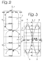
- Figures 2 and 3 illustrate the criteria, in themselves known (see, for example EP-A-1 447 068 ), that can be adopted in a system such as the one illustrated in Figure 1 for carrying out a treatment of laser cutting on articles A, each having a contour defined by two arched or C-shaped portions.
- said arched portions are designated respectively by B1 and B2.
- the embodiment described herein envisages in fact that to each of the beams B1 and B2 generated by the system 2 there is imparted a respective path of deflection such as to cause the respective beam not to define the contour of each individual article A completely, but only part thereof.
- each beam B1, B2 will be designed to describe a respective portion of the aforesaid contour.
- Each portion is defined in such a way that the movement of scanning of the article using the beam and the consequent definition of a corresponding part of contour advantageously exploits the superposition of the movement of advance of the articles along the axis z and the movement of deflection (both in a transverse direction, along the axis x, and in a longitudinal direction, along the axis z) imparted on the beams B1 and B2.
- the two beams B1 and B2 reverse their roles from one article A to the next.
- a transverse movement of deflection such as to cause the spot projected by each beam on the articles A being cut to correspond to a zigzag or approximately sinusoidal path.
- the beam B1 carries out cutting of the right-hand side whilst the beam B2 carries out cutting of the left-hand side and then, for the next article A, the beam B1 carries out cutting of the left-hand side, whilst cutting of the right-hand side is now performed by the beam B2.
- the process then passes, in the next article in the chain, to the situation where the beam B1 again carries out cutting of the right-hand side whilst the beam B2 carries out cutting of the left-hand side, and so on.
- the definitions "right-hand side” and “left-hand side”, with reference to the main median axis of the articles A are to be understood in an arbitrary way and can hence be exchanged with one another.
- the paths designated herein by B1 and B2 are constituted by serpentine or sinusoidal paths comprising half-waves that extend in an alternating and symmetrical way with respect to the principal longitudinal axis of the article A (i.e., with respect to the axis z of the drawings); said paths could, however, have an extension that is asymmetrical with respect to the aforesaid principal axis.
- each of the paths B1 and B2 has an S-shaped serpentine pattern with half-waves arranged alternately on one side and on the other with respect to the axis z, so that the paths defined by the first beam B1 and by the second beam B2 cross one another at a point corresponding to said principal axis.
- the paths B1 and B2 would present a pattern roughly resembling that of a rectified sinusoidal current with cusps located in a position corresponding to the points of crossing-over of the paths B1 and B2 in Figure 2 .
- the solution that envisages recourse to two beams may constitute a preferred solution in so far as it represents an ideal synthesis between quality of the results achieved and simplicity of realization.
- the "reference system" of Figure 2 is hence constituted by the web or chain of articles A which advances along the conveyor 7 and in which the beams produced by the deflection systems 2 describe the paths B1 and B2.
- paths such as the paths B1 and B2 illustrated in Figure 2 could be defined each by one of the beams produced by the device 2 as a result of a pure and simple movement of deflection oriented along the axis x, i.e., in a direction transverse to the axis z.
- the "half-waves" of the path B1 that are to the left with respect to the axis z could be obtained by simply deflecting the laser beam each time considered towards the left (negative values of the axis x of Figure 3 ).
- the half-waves of the path B1 that are to the right with respect to the axis z could also be generated as a result of a pure and simple movement of deflection to the right in the diagram of Figure 3 (positive values of x in said Figure 3 ). In this case, the diagram of Figure 3 would be reduced to a pure and simple horizontal segment.
- the path of deflection represented in Figure 3 is a closed path with a butterfly-shaped pattern substantially resembling a Lissajous figure: in an embodiment, each of the beams B1 and B2 produced by the systems 2 is in fact subjected, not only to a deflection along the axis x (i.e., in a direction transverse to the direction of advance of the articles A), but also to a movement of deflection along the axis z.
- a device 20 for controlling the deflection which, in a first possible embodiment of the invention, is provided with a manual regulator 22 that can be actuated by an operator.
- the control 20 is able to intervene selectively on the action of deflection exerted by the systems 2 on the beams B1 and B2 in such a way that, given the same signal emitted by the control unit, the beams B1 and B2 undergo (in the direction of the axis z) a value of deflection that is different - usually higher than - the expected one.
- the intervention of the control module 20 is to modify the figure appearing in Figure 3 so that its "dynamics" of oscillation in the direction of the axis z (originally comprised between approximately -21° and +21°, for an overall value of approximately 42°) is modified in such a way as to be equal to an angular value of approximately 42°, incremented by a y% designed to take into account the fact that the treated web (the articles A) is lengthened by x% as a result of stretching; linked to this deformation in z is another transverse one of necking down.
- the action of deflection of the beams B1 and B2 is also modified in the sense of a stretching action in the direction of the axis z so as to compensate for the phenomenon to which the film is to be subjected.
- the device 20 can be subjected to a manual control, carried out by an operator who, by observing the products coming off the system, is able to recognize reaching of the correct value of modification of the angle of deflection required to compensate for the stretch.
- the solution described herein is also suited to being implemented according to modalities of complete automation, envisaging, for example, that the unit 3 is configured (in a way in itself known) so as to detect, starting from the signals supplied by the sensor 5, the amount of stretching to which the web of articles A is subjected.
- Manual adjustment and automatic control can on the other hand coexist in the same plant, for example so as to enable manual intervention to carry out a first rough adjustment that is to be refined and maintained over time by an automatic control.
- the correction of the stretching value can be made in percentage terms, independently along the axes z and y. Said values have then the intrinsic function of modifying the profile made, enabling the user to vary the morphological characteristics of the products coming off from the system (lengthening and/or widening of the profile). In other words, within certain limits the values of stretching enable optimization of the shape apart from the fact of recovering the stretching, but precisely in order to reduce possible approximations of design.
- the operation of laser cutting is executed whilst the web or film is supported at the bottom by supporting structures comprised in the conveyor 7 and including a wire net.
- the supporting (and conveying) belt is - as illustrated schematically in Figure 1 - an endless belt that is run over end return idlers and is mobile with a synchronized motion as the web of articles A advances.
- this is a belt having a central area 72 made of a network and/or a wire net having two continuous side borders 74, for example made of plastic material such as polyurethane or silicon.
- the wire net of the central area 72 can present a width of band of approximately 190 mm, with the side borders 74 having a width of approximately 20 mm each, and an overall thickness of not more than 1.8 mm.
- the side borders 74 which can be made of silicone or polyurethane and the main function of which is to prevent rapid deterioration of the net in the event of accidental contact on the fixed side guide, during the steps of continuous running.
- the side borders 74 are also useful for balancing the structure and limiting its deformation following upon tensioning.
- a net conveyor belt of the type described above is able to withstand the aggression of the laser beam used in the cutting process, which has a spot size comprised between 100 and 300 ⁇ m. Considering the powers used (two beams of approximately 800 W installed power each) with the corresponding speed of process, this results in a supply of energy with an intensity comprised between 100 and 300 kJ/m 2 .
- Resistance to heat is not the only advantageous characteristic for the belt in the area exposed to the action of the laser beam.
- the mechanical resistance in so far as the belt is subjected to a pressure gradient (e.g. vacuum or gas jets/blows) for the purpose of stabilizing operation thereof as well as to composite dynamic stress, induced, during operation, both by the return idlers and/or the motor drive and by the mechanical action of one or more cleaning brushes 9, which, according to the experiments conducted by the applicant, it is advantageous to associate to the belts 7 (the cleaning brushes being two in number in the case of the example illustrated).
- a pressure gradient e.g. vacuum or gas jets/blows
- the brush 9 or each brush 9 is aimed at removing from the netted area 72 of the belt the molten and powdered residue of the raw materials treated, which under the action of the laser beam are in part sublimated and in part molten (areas impinged upon by the tails of the gaussian energy profile of cutting).
- the molten (or thermally altered) material subject to cutting tends to deposit in the openings of the meshes of the net and in the interstices made between the filaments (which can be of the twisted type, in particular in the case of the warp) of the netted area 72.
- the brush 9 or each brush 9 is a rotary brush with bristle made up of bronze, brass, steel or synthetic fibres, arranged according on full cover edge or to helical paths opposed to one another.
- the angle of inclination of the helix, designated by ⁇ as illustrated in Figure 5
- the brush 9 or each brush 9 is a rotary brush with bristle constituted by synthetic or metal fibres like bronze, brass, steel fibres, arranged according to a (radial and transverse) path that involves the use of low values both of pressure, between the brush 9 and the wire net 72, and of rate of rotation of the brush. This results in a reduced effect of wear of the elements involved, with consequent increase in their service life.
- the motion of the brush 9 on the wire net 72 can be either concordant or opposite, according to the geometry of the net adopted.
- the r.p.m. is clearly linked to the rate of feed of advance of the net 72 (i.e., to the speed of processing of the line), with a ratio of approximately 1:1.2.
- a feature of the embodiment described herein lies in the modalities adopted for carrying out the looped closing of the belt comprising the net 72.
- the process consists in a staggered termination of the filaments, arranged according to an alternating herring-bone pattern so as to distribute over the entire width of the netted area of the belt the termination iron "seed".
- An embodiment envisages hence closing the belt to form an endless loop by connecting the opposite ends with butt joins obtained by micro plasma welding or electro-brazing. With this procedure, the ends of each filament are welded together. As a result an openwork mesh is obtained with constant open area also in the area of closing.
- Another embodiment consists then in forming the endless belt by rigid wefting.
- the looped closing of the belt is carried out manually, by inserting, within finishing eyelets 76 set opposite to one another and mutually staggered, a weft wire 78, which guarantees correct termination thereof.
- the plant illustrated in Figure 1 also comprises various auxiliary accessories, which have the task of optimizing the performance of the plant in terms of quality and duration.
- auxiliary accessories which have the task of optimizing the performance of the plant in terms of quality and duration.
- additional blowing points for dynamic cleaning of the net of the belt 7 top mouths for suction of the fumes, removable perforated supporting plates under the cutting area for daily cleaning of the fixed base for sliding of the belt, etc.
- Figures 8 and 9 are more detailed representations of an embodiment for supporting the net 72 in correspondence with the area or zone W where the material A is intended to be cut by either of the laser beams B1, B2.
- figure 9 is an exploded view that highlights the relative positioning of some of the elements shown in figure 8 .
- reference 100 denotes a support element essentially in the form of an apertured plate, that is a plate provided with apertures. In the embodiment shown, such apertures are arranged in two arrays 102, 104 respectively.
- the apertures 102 are essentially in the forms of holes (e.g. round holes) provided in the body of the plate 100.
- the apertures 104 are essentially in the form of a grid such as e.g. a square or rectangular grid extending over the area or zone W where the material A is intended to be laser cut, i.e. the area covered by the deflection system that produces the laser beam B1 or B2.
- the apertures 104 are formed in a grid comprised of blade-like elements or vanes. These blade-like elements or vanes are arranged to form therebetween apertures (of a square shape in the exemplary embodiment shown) surrounded by side walls that substantially extend either in a vertical direction, namely a direction orthogonal to the plane of the net 72 (as shown in the drawing), or in a horizontal direction, namely a direction parallel to the plane of the net 72.
- these elements are not solidly connected to each other. In an embodiment, these elements are arranged more or less in the fashion of a grating, wherein each element retains a moderate capability of displacement with respect to the neighbouring elements. The reasons for this loose connection arrangement will be explained in greater detail in the following.
- Reference numeral 106 denotes a suction box ("vacuum chamber") intended to be connected - in a manner known per se - to a source of subatmospheric pressure V (i.e. "vacuum”) so that a level of pressure under the atmospheric pressure is established in the chamber 106.
- V subatmospheric pressure
- the suction chamber 106 will thus tend to draw air into the box 106 itself via the apertures between the wires in the net 72 and the apertures 102, 104 in the plate 100 while the material of the article A will tend to obstruct such a flow of air.
- a similar pressure gradient may be generated by means of jets of air or other gases projected (i.e. blown) towards the material of the articles A (downwardly, with reference to figures 8 and 9 ), whereby the material of the articles A will be "pressed” against the net 72 by such jets.
- the suction box 106 may be dispensed with.
- the pressure gradient may be created by using both a suction box such as suction box 106 and gas jets as described in the foregoing.
- the pressure gradient will stabilize the material of the article A against the net 72 which in turn will be supported in its sliding movement by the plate 100.
- the openings 102 and 104 will form pathways for the gas (air flow) induced by such a pressure gradient.
- the openings 104 will play an additional role in facilitating removal (e.g. by vacuum, that is by suction) of any residue of the raw materials treated which may detached from the net 72.
- such raw materials may be in part sublimated and in part molten, and such molten material may tend to deposit in the openings of the meshes of the net and in the interstices between the filaments of the net 72.
- the suction (and, in any case, the pressure gradient) exerted across the openings 104 and by manual frontal conveyer valves may be further beneficial in removing from the net 72 at least part of these residues, which are thus drawn e.g. into the suction box 106. This facilitates the cleaning action of the brush or brushes 9.
- figure 1 of the drawing shows brushes 9 located outside the loop formed by the net 72
- the applicant have found it beneficial that at least one brushes provided is arranged within the loop formed by the net 72.
- the brush in question will be arranged to clean the surface of the net 72 opposite to the surface of the net supporting the material A, thus removing therefrom those residues of laser cutting that have passed through the meshes of the net and were not removed by the pressure gradient acting across the net.
- the blade-like conformation of the elements defining the apertures 104 in correspondence with the area W has been found to exert of a sort of "scraping" (i.e doctor-blade like) action on the lower surface of the net 72 sliding thereover.
- a scraping action has been found to be particularly beneficial in avoiding accumulation of residues of molten material at the lower surface of the net 72, which is therefore kept clean. This avoids any undesired obstruction of the openings of the meshes of the net and/or the formation of any undesired "coating" at the underside of the net 72 which may undesirably “lift” (i.e. displace) the net 72 from its close sliding relationship over the upper surface of the plate 100.
- lift i.e. displace
- the joint stabilising/cleaning action was found to take place in a surprisingly effective manner when the apertured portion of the plate 100 intended to support the net 72 in correspondence with the area W of cutting of the material A by the laser beam B1 or B2 (namely the area of apertures 104) has an open area at least equal to 95% and preferably at least equal to 98%.
- open area will mean the ratio of the net open area of the apertures 104 to the surface area of the zone of the plate 100 where the openings 104 are provided - both areas being measured in the general plane of the plate 100, that is in the general plate of sliding of the net 72.
- a 500 x 500 mm. square portion of the plate 100 with a surface of 25 cm/sq having provided therein a 5 x 5 matrix arrangement of twenty-five apertures each having a net area of 0.90 cm/sq will have an opera area of 90%.
- a same square portion of the plate 100 with a surface of 25 cm/sq having provided therein a 5 x 5 matrix arrangement of twenty-five apertures each having a net area of 0.95 cm/sq will have an opera area of 95%.
- a square portion of the plate 100 with a surface of 25 cm/sq having provided therein a 5 x 5 matrix arrangement of twenty-five apertures each having a net area of 0.98 cm/sq will have an opera area of 98%.
- the exemplary embodiment of figure 9 includes a rectangular zone W with a 4x5 arrangement of identical square apertures.
Landscapes
- Engineering & Computer Science (AREA)
- Physics & Mathematics (AREA)
- Optics & Photonics (AREA)
- Plasma & Fusion (AREA)
- Mechanical Engineering (AREA)
- Laser Beam Processing (AREA)
- Absorbent Articles And Supports Therefor (AREA)
- Treatments Of Macromolecular Shaped Articles (AREA)
- Treatment Of Fiber Materials (AREA)
- Processing And Handling Of Plastics And Other Materials For Molding In General (AREA)
- Manufacture Of Macromolecular Shaped Articles (AREA)
Priority Applications (1)
| Application Number | Priority Date | Filing Date | Title |
|---|---|---|---|
| EP20070858991 EP2099578B1 (en) | 2007-01-02 | 2007-12-03 | Method for treating film material, for instance for manufacturing sanitary products |
Applications Claiming Priority (3)
| Application Number | Priority Date | Filing Date | Title |
|---|---|---|---|
| EP07425001 | 2007-01-02 | ||
| EP20070858991 EP2099578B1 (en) | 2007-01-02 | 2007-12-03 | Method for treating film material, for instance for manufacturing sanitary products |
| PCT/IB2007/003830 WO2008081239A2 (en) | 2007-01-02 | 2007-12-03 | Improvements in devices for treating film material, for instance for manufacturing sanitary products |
Publications (2)
| Publication Number | Publication Date |
|---|---|
| EP2099578A2 EP2099578A2 (en) | 2009-09-16 |
| EP2099578B1 true EP2099578B1 (en) | 2010-08-18 |
Family
ID=38072153
Family Applications (1)
| Application Number | Title | Priority Date | Filing Date |
|---|---|---|---|
| EP20070858991 Not-in-force EP2099578B1 (en) | 2007-01-02 | 2007-12-03 | Method for treating film material, for instance for manufacturing sanitary products |
Country Status (11)
| Country | Link |
|---|---|
| US (1) | US8445812B2 (pt) |
| EP (1) | EP2099578B1 (pt) |
| JP (1) | JP5187699B2 (pt) |
| CN (1) | CN101610871B (pt) |
| AT (1) | ATE477877T1 (pt) |
| BR (1) | BRPI0721203B1 (pt) |
| DE (1) | DE602007008615D1 (pt) |
| DK (1) | DK2099578T3 (pt) |
| ES (1) | ES2348289T3 (pt) |
| TW (1) | TWI398316B (pt) |
| WO (1) | WO2008081239A2 (pt) |
Families Citing this family (16)
| Publication number | Priority date | Publication date | Assignee | Title |
|---|---|---|---|---|
| US9029731B2 (en) * | 2007-01-26 | 2015-05-12 | Electro Scientific Industries, Inc. | Methods and systems for laser processing continuously moving sheet material |
| JP5513167B2 (ja) * | 2009-03-02 | 2014-06-04 | ユニ・チャーム株式会社 | コンベア装置及び吸収性物品の製造方法 |
| EP2258639B1 (en) | 2009-06-03 | 2012-01-04 | Fameccanica.Data S.p.A. | A conveyor device for laser treatments |
| US8191701B2 (en) * | 2010-10-12 | 2012-06-05 | Xerox Corporation | Belt cleaning system for laser cutting device |
| CN103260814B (zh) * | 2010-12-30 | 2017-03-29 | 3M创新有限公司 | 使用具有金面层的支撑构件进行激光切割的设备和方法 |
| IT1404309B1 (it) * | 2011-02-24 | 2013-11-22 | Gdm Spa | Macchina confezionatrice di articoli assorbenti igienici, quali pannolini, tamponi o simili. |
| WO2012174351A1 (en) * | 2011-06-16 | 2012-12-20 | Preco, Inc. | Laser processing system and method of use |
| CN103600172B (zh) * | 2013-04-28 | 2017-02-08 | 宝山钢铁股份有限公司 | 一种开卷落料方法 |
| RU2562584C1 (ru) * | 2014-07-22 | 2015-09-10 | Российская Федерация, от имени которой выступает Министерство промышленности и торговли Российской Федерации (Минпромторг России) | Способ формирования дискретного износостойкого покрытия на детали |
| JP2018502611A (ja) | 2014-11-07 | 2018-02-01 | ザ プロクター アンド ギャンブル カンパニー | レーザー源を使用した吸収性物品の製造のための方法及び装置 |
| CN104787370B (zh) * | 2015-04-01 | 2018-10-02 | 金湖三木机械制造实业有限公司 | 卫生用品自动分堆计数装箱装置 |
| BR112018010732B1 (pt) * | 2015-12-18 | 2022-08-23 | Kimberly-Clark Worldwide, Inc | Método de corte de uma estrutura de manta |
| US10806635B2 (en) | 2016-03-15 | 2020-10-20 | The Procter & Gamble Company | Methods and apparatuses for separating and positioning discrete articles |
| DE102017004318B3 (de) * | 2017-04-27 | 2018-04-05 | Maximilian Setterl | Vorrichtung und Verfahren zum Transportieren und Bearbeiten von Halbzeugen |
| CN109132434A (zh) * | 2018-11-02 | 2019-01-04 | 新汶矿业集团有限责任公司 | 一种双向煤矸皮带运输装置 |
| US12409080B2 (en) | 2019-10-22 | 2025-09-09 | Essity Hygiene And Health Aktiebolag | Pant-type garment and method for the production thereof |
Family Cites Families (13)
| Publication number | Priority date | Publication date | Assignee | Title |
|---|---|---|---|---|
| US1278537A (en) | 1918-03-02 | 1918-09-10 | Ferdinand M Wegner | Fur-shearing machine and fur-unhairing machine. |
| US3360733A (en) | 1964-11-12 | 1967-12-26 | Boeing Co | Plasma formation and particle acceleration by pulsed laser |
| JPS61145882A (ja) | 1984-12-20 | 1986-07-03 | Mitsubishi Electric Corp | レ−ザ加工装置 |
| JPS61189896A (ja) * | 1985-02-18 | 1986-08-23 | Mitsubishi Electric Corp | レ−ザ加工装置 |
| JPS6478694A (en) * | 1987-09-19 | 1989-03-24 | Hitachi Maxell | Method and device for cutting raw film consisting of plastic film as base material |
| JPH01245990A (ja) | 1988-03-29 | 1989-10-02 | Haitekuno:Kk | レーザー切断装置 |
| JP2505273Y2 (ja) * | 1990-01-26 | 1996-07-24 | 池上通信機株式会社 | 被検体搬送装置 |
| WO1993006963A1 (fr) | 1991-09-30 | 1993-04-15 | Nippei Toyama Corporation | Appareil et procede d'usinage par laser |
| US5365816A (en) * | 1993-06-22 | 1994-11-22 | Design Systems, Inc. | Beam cutter |
| US5585017A (en) * | 1993-09-13 | 1996-12-17 | James; William A. | Defocused laser drilling process for forming a support member of a fabric forming device |
| EP1447068A1 (en) * | 2003-02-14 | 2004-08-18 | Fameccanica.Data S.p.A. | Process and device for the localised treatment of articles, for example hygienic and sanitary products |
| GB2422479B (en) | 2003-04-15 | 2006-12-13 | Ceres Power Ltd | Solid oxide fuel cell with a novel substrate and a method for fabricating the same |
| DE602005005464T2 (de) * | 2005-06-21 | 2009-04-23 | Fameccanica Data S.P.A. | Verfahren und Vorrichtung zum Laserschneiden von Artikeln, insbesondere Sanitärprodukten und ihren Bestandteilen, mit einem Laserfokuspunktdurchmesser von 0.1 bis 0.3 mm |
-
2007
- 2007-12-03 ES ES07858991T patent/ES2348289T3/es active Active
- 2007-12-03 BR BRPI0721203A patent/BRPI0721203B1/pt not_active IP Right Cessation
- 2007-12-03 JP JP2009543532A patent/JP5187699B2/ja not_active Expired - Fee Related
- 2007-12-03 EP EP20070858991 patent/EP2099578B1/en not_active Not-in-force
- 2007-12-03 WO PCT/IB2007/003830 patent/WO2008081239A2/en not_active Ceased
- 2007-12-03 CN CN2007800512506A patent/CN101610871B/zh not_active Expired - Fee Related
- 2007-12-03 AT AT07858991T patent/ATE477877T1/de not_active IP Right Cessation
- 2007-12-03 DK DK07858991T patent/DK2099578T3/da active
- 2007-12-03 DE DE200760008615 patent/DE602007008615D1/de active Active
- 2007-12-03 US US12/522,080 patent/US8445812B2/en not_active Expired - Fee Related
- 2007-12-28 TW TW96150726A patent/TWI398316B/zh not_active IP Right Cessation
Also Published As
| Publication number | Publication date |
|---|---|
| DK2099578T3 (da) | 2010-11-22 |
| BRPI0721203A2 (pt) | 2014-03-18 |
| WO2008081239A3 (en) | 2008-08-28 |
| JP2010514571A (ja) | 2010-05-06 |
| EP2099578A2 (en) | 2009-09-16 |
| US8445812B2 (en) | 2013-05-21 |
| ATE477877T1 (de) | 2010-09-15 |
| DE602007008615D1 (de) | 2010-09-30 |
| ES2348289T3 (es) | 2010-12-02 |
| CN101610871B (zh) | 2012-06-20 |
| WO2008081239A2 (en) | 2008-07-10 |
| BRPI0721203B1 (pt) | 2016-02-10 |
| US20100044354A1 (en) | 2010-02-25 |
| TW200911436A (en) | 2009-03-16 |
| JP5187699B2 (ja) | 2013-04-24 |
| CN101610871A (zh) | 2009-12-23 |
| TWI398316B (zh) | 2013-06-11 |
| WO2008081239A8 (en) | 2008-10-16 |
Similar Documents
| Publication | Publication Date | Title |
|---|---|---|
| EP2099578B1 (en) | Method for treating film material, for instance for manufacturing sanitary products | |
| EP1736272B9 (en) | A method and device for laser cutting articles, in particular sanitary products and components thereof, with a laser spot diameter between 0.1 and 0.3 mm | |
| US6207925B1 (en) | Apparatus for cutting and/or welding flexible packaging | |
| US6945922B2 (en) | System for cutting a moving web in the cross direction to form sheets of a given length at high web speeds | |
| CN101821065B (zh) | 在至少一次分离工序中保持板状材料的设备 | |
| US10799981B2 (en) | Laser processing system and method of use | |
| EP3677374B1 (en) | Manufacturing method for join body and manufacturing apparatus for join body | |
| EP3677377B1 (en) | Method and device for manufacturing joined body | |
| EP1447068A1 (en) | Process and device for the localised treatment of articles, for example hygienic and sanitary products | |
| US6013895A (en) | System and method for perforating sheet material | |
| JP2003227062A (ja) | 不織布加工物品 | |
| EP3170611B1 (en) | Continuous web laser treatment module | |
| EP3098018A1 (en) | Singulation conveyor | |
| JP7308170B2 (ja) | 熱加工機のワーク支持体 | |
| EP3677376B1 (en) | Method of and apparatus for manufacturing a joined body, and joined body | |
| CN114846254A (zh) | 具有超声波或激光切口侧边的传送带特别是锭带 | |
| EP3434410A1 (en) | Continuous web laser treatment module with two flat path treatment portions | |
| JPH01245991A (ja) | レーザー切断装置 | |
| EP3677375B1 (en) | Joint body, manufacturing method for joint body, and manufacturing apparatus for joint body | |
| US20160346874A1 (en) | Singulation conveyor | |
| JP2021070046A (ja) | ワーク・サポート・テーブルに用いるワーク支持体および熱加工機 | |
| JP2014012289A (ja) | ミシン目形成装置 |
Legal Events
| Date | Code | Title | Description |
|---|---|---|---|
| PUAI | Public reference made under article 153(3) epc to a published international application that has entered the european phase |
Free format text: ORIGINAL CODE: 0009012 |
|
| 17P | Request for examination filed |
Effective date: 20090626 |
|
| AK | Designated contracting states |
Kind code of ref document: A2 Designated state(s): AT BE BG CH CY CZ DE DK EE ES FI FR GB GR HU IE IS IT LI LT LU LV MC MT NL PL PT RO SE SI SK TR |
|
| RTI1 | Title (correction) |
Free format text: METHOD FOR TREATING FILM MATERIAL, FOR INSTANCE FOR MANUFACTURING SANITARY PRODUCTS |
|
| GRAP | Despatch of communication of intention to grant a patent |
Free format text: ORIGINAL CODE: EPIDOSNIGR1 |
|
| DAX | Request for extension of the european patent (deleted) | ||
| GRAS | Grant fee paid |
Free format text: ORIGINAL CODE: EPIDOSNIGR3 |
|
| GRAA | (expected) grant |
Free format text: ORIGINAL CODE: 0009210 |
|
| AK | Designated contracting states |
Kind code of ref document: B1 Designated state(s): AT BE BG CH CY CZ DE DK EE ES FI FR GB GR HU IE IS IT LI LT LU LV MC MT NL PL PT RO SE SI SK TR |
|
| REG | Reference to a national code |
Ref country code: GB Ref legal event code: FG4D |
|
| REG | Reference to a national code |
Ref country code: CH Ref legal event code: EP |
|
| REG | Reference to a national code |
Ref country code: IE Ref legal event code: FG4D |
|
| REF | Corresponds to: |
Ref document number: 602007008615 Country of ref document: DE Date of ref document: 20100930 Kind code of ref document: P |
|
| REG | Reference to a national code |
Ref country code: CH Ref legal event code: NV Representative=s name: ISLER & PEDRAZZINI AG |
|
| REG | Reference to a national code |
Ref country code: DK Ref legal event code: T3 Ref country code: ES Ref legal event code: FG2A Effective date: 20101122 |
|
| REG | Reference to a national code |
Ref country code: SE Ref legal event code: TRGR |
|
| REG | Reference to a national code |
Ref country code: NL Ref legal event code: VDEP Effective date: 20100818 |
|
| LTIE | Lt: invalidation of european patent or patent extension |
Effective date: 20100818 |
|
| PG25 | Lapsed in a contracting state [announced via postgrant information from national office to epo] |
Ref country code: LT Free format text: LAPSE BECAUSE OF FAILURE TO SUBMIT A TRANSLATION OF THE DESCRIPTION OR TO PAY THE FEE WITHIN THE PRESCRIBED TIME-LIMIT Effective date: 20100818 Ref country code: FI Free format text: LAPSE BECAUSE OF FAILURE TO SUBMIT A TRANSLATION OF THE DESCRIPTION OR TO PAY THE FEE WITHIN THE PRESCRIBED TIME-LIMIT Effective date: 20100818 Ref country code: AT Free format text: LAPSE BECAUSE OF FAILURE TO SUBMIT A TRANSLATION OF THE DESCRIPTION OR TO PAY THE FEE WITHIN THE PRESCRIBED TIME-LIMIT Effective date: 20100818 |
|
| PG25 | Lapsed in a contracting state [announced via postgrant information from national office to epo] |
Ref country code: PT Free format text: LAPSE BECAUSE OF FAILURE TO SUBMIT A TRANSLATION OF THE DESCRIPTION OR TO PAY THE FEE WITHIN THE PRESCRIBED TIME-LIMIT Effective date: 20101220 Ref country code: PL Free format text: LAPSE BECAUSE OF FAILURE TO SUBMIT A TRANSLATION OF THE DESCRIPTION OR TO PAY THE FEE WITHIN THE PRESCRIBED TIME-LIMIT Effective date: 20100818 Ref country code: SI Free format text: LAPSE BECAUSE OF FAILURE TO SUBMIT A TRANSLATION OF THE DESCRIPTION OR TO PAY THE FEE WITHIN THE PRESCRIBED TIME-LIMIT Effective date: 20100818 Ref country code: IS Free format text: LAPSE BECAUSE OF FAILURE TO SUBMIT A TRANSLATION OF THE DESCRIPTION OR TO PAY THE FEE WITHIN THE PRESCRIBED TIME-LIMIT Effective date: 20101218 Ref country code: CY Free format text: LAPSE BECAUSE OF FAILURE TO SUBMIT A TRANSLATION OF THE DESCRIPTION OR TO PAY THE FEE WITHIN THE PRESCRIBED TIME-LIMIT Effective date: 20100818 Ref country code: BG Free format text: LAPSE BECAUSE OF FAILURE TO SUBMIT A TRANSLATION OF THE DESCRIPTION OR TO PAY THE FEE WITHIN THE PRESCRIBED TIME-LIMIT Effective date: 20101118 |
|
| PG25 | Lapsed in a contracting state [announced via postgrant information from national office to epo] |
Ref country code: NL Free format text: LAPSE BECAUSE OF FAILURE TO SUBMIT A TRANSLATION OF THE DESCRIPTION OR TO PAY THE FEE WITHIN THE PRESCRIBED TIME-LIMIT Effective date: 20100818 Ref country code: GR Free format text: LAPSE BECAUSE OF FAILURE TO SUBMIT A TRANSLATION OF THE DESCRIPTION OR TO PAY THE FEE WITHIN THE PRESCRIBED TIME-LIMIT Effective date: 20101119 Ref country code: LV Free format text: LAPSE BECAUSE OF FAILURE TO SUBMIT A TRANSLATION OF THE DESCRIPTION OR TO PAY THE FEE WITHIN THE PRESCRIBED TIME-LIMIT Effective date: 20100818 |
|
| PG25 | Lapsed in a contracting state [announced via postgrant information from national office to epo] |
Ref country code: EE Free format text: LAPSE BECAUSE OF FAILURE TO SUBMIT A TRANSLATION OF THE DESCRIPTION OR TO PAY THE FEE WITHIN THE PRESCRIBED TIME-LIMIT Effective date: 20100818 Ref country code: CZ Free format text: LAPSE BECAUSE OF FAILURE TO SUBMIT A TRANSLATION OF THE DESCRIPTION OR TO PAY THE FEE WITHIN THE PRESCRIBED TIME-LIMIT Effective date: 20100818 Ref country code: SK Free format text: LAPSE BECAUSE OF FAILURE TO SUBMIT A TRANSLATION OF THE DESCRIPTION OR TO PAY THE FEE WITHIN THE PRESCRIBED TIME-LIMIT Effective date: 20100818 Ref country code: RO Free format text: LAPSE BECAUSE OF FAILURE TO SUBMIT A TRANSLATION OF THE DESCRIPTION OR TO PAY THE FEE WITHIN THE PRESCRIBED TIME-LIMIT Effective date: 20100818 |
|
| PLBE | No opposition filed within time limit |
Free format text: ORIGINAL CODE: 0009261 |
|
| STAA | Information on the status of an ep patent application or granted ep patent |
Free format text: STATUS: NO OPPOSITION FILED WITHIN TIME LIMIT |
|
| 26N | No opposition filed |
Effective date: 20110519 |
|
| PG25 | Lapsed in a contracting state [announced via postgrant information from national office to epo] |
Ref country code: MC Free format text: LAPSE BECAUSE OF NON-PAYMENT OF DUE FEES Effective date: 20101231 |
|
| REG | Reference to a national code |
Ref country code: DE Ref legal event code: R097 Ref document number: 602007008615 Country of ref document: DE Effective date: 20110519 |
|
| PG25 | Lapsed in a contracting state [announced via postgrant information from national office to epo] |
Ref country code: IE Free format text: LAPSE BECAUSE OF NON-PAYMENT OF DUE FEES Effective date: 20101203 |
|
| PG25 | Lapsed in a contracting state [announced via postgrant information from national office to epo] |
Ref country code: MT Free format text: LAPSE BECAUSE OF FAILURE TO SUBMIT A TRANSLATION OF THE DESCRIPTION OR TO PAY THE FEE WITHIN THE PRESCRIBED TIME-LIMIT Effective date: 20100818 Ref country code: IT Free format text: LAPSE BECAUSE OF NON-PAYMENT OF DUE FEES Effective date: 20101203 |
|
| PG25 | Lapsed in a contracting state [announced via postgrant information from national office to epo] |
Ref country code: LU Free format text: LAPSE BECAUSE OF NON-PAYMENT OF DUE FEES Effective date: 20101203 Ref country code: HU Free format text: LAPSE BECAUSE OF FAILURE TO SUBMIT A TRANSLATION OF THE DESCRIPTION OR TO PAY THE FEE WITHIN THE PRESCRIBED TIME-LIMIT Effective date: 20110219 |
|
| PG25 | Lapsed in a contracting state [announced via postgrant information from national office to epo] |
Ref country code: TR Free format text: LAPSE BECAUSE OF FAILURE TO SUBMIT A TRANSLATION OF THE DESCRIPTION OR TO PAY THE FEE WITHIN THE PRESCRIBED TIME-LIMIT Effective date: 20100818 |
|
| REG | Reference to a national code |
Ref country code: FR Ref legal event code: PLFP Year of fee payment: 9 |
|
| REG | Reference to a national code |
Ref country code: FR Ref legal event code: PLFP Year of fee payment: 10 |
|
| REG | Reference to a national code |
Ref country code: FR Ref legal event code: PLFP Year of fee payment: 11 |
|
| PGFP | Annual fee paid to national office [announced via postgrant information from national office to epo] |
Ref country code: DK Payment date: 20181221 Year of fee payment: 12 |
|
| PGFP | Annual fee paid to national office [announced via postgrant information from national office to epo] |
Ref country code: FR Payment date: 20181227 Year of fee payment: 12 Ref country code: CH Payment date: 20181227 Year of fee payment: 12 Ref country code: GB Payment date: 20181221 Year of fee payment: 12 Ref country code: BE Payment date: 20181221 Year of fee payment: 12 Ref country code: IT Payment date: 20181213 Year of fee payment: 12 |
|
| PGFP | Annual fee paid to national office [announced via postgrant information from national office to epo] |
Ref country code: ES Payment date: 20190131 Year of fee payment: 12 Ref country code: DE Payment date: 20190228 Year of fee payment: 12 |
|
| PGFP | Annual fee paid to national office [announced via postgrant information from national office to epo] |
Ref country code: SE Payment date: 20181228 Year of fee payment: 12 |
|
| REG | Reference to a national code |
Ref country code: DE Ref legal event code: R119 Ref document number: 602007008615 Country of ref document: DE |
|
| REG | Reference to a national code |
Ref country code: DK Ref legal event code: EBP Effective date: 20191231 |
|
| REG | Reference to a national code |
Ref country code: SE Ref legal event code: EUG |
|
| REG | Reference to a national code |
Ref country code: CH Ref legal event code: PL |
|
| REG | Reference to a national code |
Ref country code: BE Ref legal event code: MM Effective date: 20191231 |
|
| GBPC | Gb: european patent ceased through non-payment of renewal fee |
Effective date: 20191203 |
|
| PG25 | Lapsed in a contracting state [announced via postgrant information from national office to epo] |
Ref country code: IT Free format text: LAPSE BECAUSE OF NON-PAYMENT OF DUE FEES Effective date: 20191203 Ref country code: SE Free format text: LAPSE BECAUSE OF NON-PAYMENT OF DUE FEES Effective date: 20191204 Ref country code: FR Free format text: LAPSE BECAUSE OF NON-PAYMENT OF DUE FEES Effective date: 20191231 Ref country code: GB Free format text: LAPSE BECAUSE OF NON-PAYMENT OF DUE FEES Effective date: 20191203 Ref country code: DE Free format text: LAPSE BECAUSE OF NON-PAYMENT OF DUE FEES Effective date: 20200701 |
|
| PG25 | Lapsed in a contracting state [announced via postgrant information from national office to epo] |
Ref country code: CH Free format text: LAPSE BECAUSE OF NON-PAYMENT OF DUE FEES Effective date: 20191231 Ref country code: BE Free format text: LAPSE BECAUSE OF NON-PAYMENT OF DUE FEES Effective date: 20191231 Ref country code: LI Free format text: LAPSE BECAUSE OF NON-PAYMENT OF DUE FEES Effective date: 20191231 |
|
| PG25 | Lapsed in a contracting state [announced via postgrant information from national office to epo] |
Ref country code: DK Free format text: LAPSE BECAUSE OF NON-PAYMENT OF DUE FEES Effective date: 20191231 |
|
| REG | Reference to a national code |
Ref country code: ES Ref legal event code: FD2A Effective date: 20210601 |
|
| PG25 | Lapsed in a contracting state [announced via postgrant information from national office to epo] |
Ref country code: ES Free format text: LAPSE BECAUSE OF NON-PAYMENT OF DUE FEES Effective date: 20191204 |