EP2099663B1 - Verfahren zum bestimmen mindestens eines parameters, der mindestens eine interaktion entlang einer längsrichtung zwischen einem reifen für fahrzeuge und dem boden darstellt - Google Patents
Verfahren zum bestimmen mindestens eines parameters, der mindestens eine interaktion entlang einer längsrichtung zwischen einem reifen für fahrzeuge und dem boden darstellt Download PDFInfo
- Publication number
- EP2099663B1 EP2099663B1 EP06831602A EP06831602A EP2099663B1 EP 2099663 B1 EP2099663 B1 EP 2099663B1 EP 06831602 A EP06831602 A EP 06831602A EP 06831602 A EP06831602 A EP 06831602A EP 2099663 B1 EP2099663 B1 EP 2099663B1
- Authority
- EP
- European Patent Office
- Prior art keywords
- parameter
- tyre
- representative
- radial deformation
- time
- Prior art date
- Legal status (The legal status is an assumption and is not a legal conclusion. Google has not performed a legal analysis and makes no representation as to the accuracy of the status listed.)
- Active
Links
Images





Classifications
-
- B—PERFORMING OPERATIONS; TRANSPORTING
- B60—VEHICLES IN GENERAL
- B60T—VEHICLE BRAKE CONTROL SYSTEMS OR PARTS THEREOF; BRAKE CONTROL SYSTEMS OR PARTS THEREOF, IN GENERAL; ARRANGEMENT OF BRAKING ELEMENTS ON VEHICLES IN GENERAL; PORTABLE DEVICES FOR PREVENTING UNWANTED MOVEMENT OF VEHICLES; VEHICLE MODIFICATIONS TO FACILITATE COOLING OF BRAKES
- B60T8/00—Arrangements for adjusting wheel-braking force to meet varying vehicular or ground-surface conditions, e.g. limiting or varying distribution of braking force
- B60T8/17—Using electrical or electronic regulation means to control braking
- B60T8/172—Determining control parameters used in the regulation, e.g. by calculations involving measured or detected parameters
- B60T8/1725—Using tyre sensors, e.g. Sidewall Torsion sensors [SWT]
-
- B—PERFORMING OPERATIONS; TRANSPORTING
- B60—VEHICLES IN GENERAL
- B60T—VEHICLE BRAKE CONTROL SYSTEMS OR PARTS THEREOF; BRAKE CONTROL SYSTEMS OR PARTS THEREOF, IN GENERAL; ARRANGEMENT OF BRAKING ELEMENTS ON VEHICLES IN GENERAL; PORTABLE DEVICES FOR PREVENTING UNWANTED MOVEMENT OF VEHICLES; VEHICLE MODIFICATIONS TO FACILITATE COOLING OF BRAKES
- B60T2240/00—Monitoring, detecting wheel/tyre behaviour; counteracting thereof
- B60T2240/04—Tyre deformation
Definitions
- the present invention relates to a method of determining at least one parameter representative of at least one interaction along a longitudinal direction between a vehicle tyre and the ground.
- the invention concerns determining of a parameter representative of the longitudinal force to which the tyre is submitted in the footprint area and/or of the tyre slippage in a longitudinal direction.
- the invention also relates to an apparatus for determining said parameter.
- footprint area the contact region between the tyre and ground
- the interactions that are herein taken into account are those generated in a longitudinal direction, i.e. the direction along which the vehicle to which the tyre is mounted runs.
- Determining said interactions enables an indirect evaluation of the friction generated between the tyre and ground, thus allowing the electronic system mounted on the vehicle to automatically act on the vehicle movements, above all in case of sudden accelerating or braking actions, which conditions are generally riskier for the driver who will lose the vehicle's control.
- the United States patent No. 5,913,240 discloses a system for determining the longitudinal forces generated between the tyre and ground, which system comprises at least one pair of markers mounted on the tyre to different radial distances from the hub, and at least one pair of detectors fixedly mounted on the vehicle chassis so as to detect passage of the markers at each revolution of the wheel.
- phase displacement is representative of the deformation to which the tyre has been submitted following braking or acceleration for example.
- the United States patent No. 6,550,320 discloses a system for determining the forces generated at the footprint area by exploiting the detection of a SWT (Side Wall Torsion) sensor of the magnetic type and the processing operations carried out through a neural network or bilinear equations.
- SWT ide Wall Torsion
- the following forces acting on the tyre can be calculated: side force, circumferential torque, longitudinal force and vertical force.
- the United States patent No. 6,904,351 discloses a control system for vehicles in which the longitudinal force exerted on the tyre is calculated as a function of the driving torque applied to the wheel, the braking torque applied to the wheel, the vertical force, the moment of inertia of the wheel, the rotation speed of the wheel and the radius of the wheel itself.
- footprint area it is intended the portion of outer surface of the tyre in contact with the ground at a given time instant.
- the footprint area is herein defined between a first longitudinal end corresponding to the point at which the tyre comes into contact with the ground, and a second longitudinal end corresponding to the point at which the tyre separates from the ground.
- the Applicant therefore has become aware of the fact that it is possible to determine said interactions between tyre and ground in a simple and reliable manner by defining one or more indices showing a correlation with the forces that must be evaluated.
- the determination of these indices starts from detection of the radial deformations suffered by the tyre, in particular in the neighbourhood of the ends of the footprint area, and/or from determining magnitudes connected thereto, such as the rate of radial deformation and acceleration of radial deformation, for example.
- the Applicant has observed that in the profiles representative of the tyre deformation, it is possible to identify some characteristic points the coordinates of which can be combined with each other so as to supply useful information on the interactions between tyre and ground.
- the Applicant has ultimately found that by correlating the data obtained from the deformation profiles with a parameter that is a function of the angular velocity of the tyre, it is possible to define indices showing a correlation with the magnitudes that must be determined.
- a set of indices is determined starting from a first parameter representative of a radial deformation of the tyre; in particular, a first and a second values of this parameter are determined, through evaluation of the latter in a predetermined neighbourhood of the first longitudinal end of the footprint area and in a predetermined neighbourhood of the second longitudinal end of the footprint area, respectively.
- a main parameter is calculated which is representative of at least one interaction along a longitudinal direction between the tyre and ground, in the footprint area.
- the present invention relates to a method of determining at least one parameter representative of at least one interaction along a longitudinal direction between a tyre and ground, in which a footprint area is defined between a first and a second longitudinal ends, said method comprising the following steps:
- the invention relates to an apparatus for determining at least one parameter which is representative of at least one interaction along a longitudinal direction between a tyre and the ground, wherein a footprint area is defined between a first and a second longitudinal ends, said apparatus comprising:
- a tyre used for carrying out the method in accordance with the invention has been generally denoted at 1.
- Tyre 1 ( Fig. 1a ) is mounted on a rim 2, in turn mounted on a hub 3; through the hub 3 tyre 1 is associated with a vehicle (not shown) to allow running thereof. During the vehicle running, tyre 1 rolls on the ground and is submitted to a displacement in a longitudinal direction substantially parallel to the ground itself.
- tyre 1 is in contact with the ground in the so-called "footprint area" 4, which area is defined between a first and a second longitudinal ends 4a, 4b.
- the method of the invention first of all comprises a step of identifying a first parameter P11, P12, P13 representative of a radial deformation of tyre 1.
- this first parameter P11, P12, P13 can be the true radial deformation, the rate of radial deformation, or the acceleration of radial deformation; depending on the selected type of parameter, a different technique will be adopted to determine the interactions in the longitudinal direction between tyre 1 and the ground.
- rate of deformation and acceleration of deformation do not directly provide the information relating to the amount of radial deformation of the tyre
- said rate and acceleration are in any case important parameters in evaluating the deformation and the features of said deformation, and can therefore be considered as parameters representative of the radial deformation of the tyre.
- the method of the invention further comprises a step of detecting through a sensor 6 positioned on the radially internal surface 5 of tyre 1 ( Fig. 1b ), a detection magnitude representative of a radial deformation of tyre 1, and a step of generating a main signal 100 incorporating said detection magnitude.
- Sensor 6 is preferably positioned in an equatorial plane E of tyre 1.
- the first parameter P11, P12, P13 is then determined depending on this main signal 100 and the detection magnitude incorporated therein.
- Sensor 6 can be an accelerometer for example, that is suitably fastened to said radially internal surface 5 of tyre 1.
- the detection magnitude can be the acceleration of radial deformation; starting from the latter, if necessary, it will be possible to calculate the rate of radial deformation (through an integration operation) and/or the radial deformation (through two integration operations).
- the main signal 100 is acquired to a frequency included between 1 kHz and 15 kHz (e.g. equal to 4 kHz) and is then multiplied by suitable factors in order to obtain a conversion from volts to m/s 2 .
- the main signal 100 is filtered, at least for eliminating the average value thereof and make the processing operations to be carried out afterwards lighter as regards their computational profile.
- the filtering operation can be of the band-pass type, carried out between a first pulsation ⁇ 1 and a second pulsation ⁇ 2 .
- the ratio between the first pulsation ⁇ 1 and the angular velocity ⁇ 0 of the tyre is preferably included between 0,5 and 5, and in particular included between 1 and 2.
- the ratio between the second pulsation ⁇ 2 and the angular velocity ⁇ 0 of the tyre is preferably included between 10 and 30, and in particular included between 15 and 20.
- a step of reconstruction of the first parameter itself can be provided, depending on the harmonics still present after filtering.
- a first and a second values of the first parameter P11, P12, P13 are determined; the first value is determined in a neighbourhood of the first longitudinal end 4a of the footprint area 4, while the second value is determined in a neighbourhood of the second longitudinal end 4b of the footprint area 4.
- the point within said neighbourhoods is determined where the first parameter P11, P12, P13 is to be evaluated to obtain the first and second values.
- the method of the invention further contemplates a step of calculating a linear combination of the first and second values, so as to obtain a second parameter P21, P22, P23; preferably the linear combination can consist of a sum or a difference, depending on the parameter that is wished to be calculated.
- the method in addition comprises a step of determining a third parameter P31, P32, P33 representative of the angular velocity ⁇ 0 of tyre 1, and a step of calculating a ratio between the second and third parameters, thereby obtaining a respective index A, B, C.
- the angular velocity ⁇ 0 of tyre 1 can be determined starting from the main signal 100 for example, or a trigger signal can be exploited which enables the time instant at which tyre 1 has completed a full revolution to be identified.
- a main parameter PP representative of at least one interaction along the longitudinal direction between tyre 1 and the ground is calculated through a suitable algorithm.
- This main parameter PP can be indicative of slippage of tyre 1 in a longitudinal direction and/or of the longitudinal force that is generated between tyre 1 and the ground.
- the algorithm is employed in combination with a series of prestored and suitably defined coefficients for execution of the requested calculation.
- the first parameter P11 is the radial deformation of tyre 1.
- This radial deformation can be calculated starting from the acceleration of radial deformation detected, for example, by means of an accelerometer (sensor 6) that is mounted on the radially internal surface 5 of tyre 1, and by carrying out two subsequent integration operations relative to time.
- the radial-deformation signal (i.e. the first parameter P11) is reconstructed by summing up the harmonics included in the considered frequency range in the filtering step, each multiplied by the respective weight.
- the first value of the first parameter P11 is obtained through evaluation of the first parameter P11 itself at the first longitudinal end 4a of the footprint area 4 at a predetermined time instant.
- the second value of the first parameter P11 is obtained through evaluation of the first parameter P11 itself at the second longitudinal end 4b of the footprint area 4 at a different predetermined time instant.
- the following can be carried out for determining the first and second values of the first parameter P11.
- a curve is defined (i.e. calculated) that represents the radial deformation to which tyre 1 has been submitted against time, within a time interval corresponding to a wheel revolution ( Fig. 2 ).
- sensor 6 When a revolution has been completed, sensor 6 has supplied all necessary data for definition of the curve having the time in the x-axis and a measurement of the radial deformation in the y-axis.
- first and second ends 4a, 4b of the footprint area 4 correspond to the passages through zero immediately preceding and immediately following the absolute maximum, of the curve representative of the acceleration of radial deformation against time.
- the method of the invention can be carried out also if mounting of sensor 6 takes place according to an orientation opposite to the one considered until now, and taking into account points of minimum instead of points of maximum and, vice versa, points of maximum instead of points of minimum.
- the instants of absolute minimum and absolute maximum respectively of the graph representative of the rate of radial deformation against time can be taken into account (in this case carrying out a single integration operation relative to time, starting from the acceleration of radial deformation), so as to avoid possible inaccuracies due to an excessive number of passages through zero in the acceleration graph, caused by particularly intense high-frequency harmonics.
- the first end (i.e. the entry point) of the footprint area is identified by the absolute minimum, on the wheel revolution, of the tangential acceleration, while the second end (i.e. the exit point) of the footprint area is identified by the absolute maximum, on the wheel revolution, of the tangential acceleration.
- the linear combination (second parameter P21) between the first and second values is preferably a subtraction, and is therefore indicative of the difference between the radial deformation occurring at the entry of the footprint area 4 and the radial deformation occurring at the exit of the footprint area 4.
- the third parameter P31 representative of the angular velocity ⁇ 0 of tyre 1 is preferably the longitudinal length of the footprint area 4.
- the length of the footprint area 4 can be calculated by multiplying the angular velocity ⁇ 0 of the tyre by the average radius R of the tyre itself, and by a time factor ⁇ t, representative of the time duration of the interval spent by sensor 6 within the footprint area 4.
- the time factor ⁇ t can be calculated as the time distance between the two instants t i , t u identified above, as corresponding to the longitudinal ends 4a, 4b of the footprint area 4.
- said factor or parameter ⁇ t which is representative of a time duration, represents the necessary time for a point integral with the radially internal surface 5 of tyre 1 to move from the first to the second longitudinal end 4a, 4b of the footprint area 4 during rolling of the tyre 1 itself.
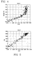
- Fig. 4 shows the correlation between A and the longitudinal slippage of the tyre in the case of a tyre P6 size 195/65 R16
- Fig. 5 shows the correlation between A and the longitudinal force generated between the tyre and the ground.in the footprint area.
- the first parameter P12 is the rate of radial deformation. This rate of radial deformation can be calculated starting from detection of the radial acceleration for example, and executing an integration operation relative to time.
- the signal of radial-deformation rate (i.e. the first parameter P12) is reconstructed by summing up the harmonics included in the considered range of frequencies in the filtering step, each multiplied by the respective weight.
- the first value of the first parameter P12 is obtained through evaluation of the first parameter P12 at the first longitudinal end 4a of the footprint area 4 at a predetermined time instant.
- the second value of the first parameter P12 is obtained through evaluation of the first parameter P12 at the second longitudinal end 4b of the footprint area 4 at a different predetermined time interval.
- the following can be carried out.
- time instants t i , t u corresponding to the first and second longitudinal ends 4a, 4b of the footprint area 4 are identified, in quite the same manner as in the preceding execution step of the method of the invention: i.e. these instants can be identified as zero-crossings of the curve of acceleration of radial deformation, or as the points of absolute maximum and absolute minimum in a wheel revolution of the acceleration of tangential deformation.
- calculation of the linear combination between the first and second values i.e. calculation of the second parameter P22 is carried out by executing a sum between said first and second values.
- the third parameter P32 representative of the angular velocity ⁇ 0 of tyre 1 is preferably calculated by multiplying the angular velocity ⁇ 0 of tyre 1 by the value of the average radius R of the tyre 1 itself.
- the step of calculating the third parameter P32 further comprises a step of multiplying the angular velocity ⁇ 0 and the average radius R by a factor included between -1.5 and -5, and in particular equal to -2.
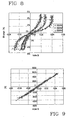
- Fig. 8 shows the correlation between B and the longitudinal slippage of the tyre (with different vertical loads corresponding to 2000, 3500 and 5000 N) in the case of a tyre P6 size 195/65 R16
- Fig. 9 still for the same tyre shows the correlation between B and the longitudinal force generated between the tyre and the ground in the footprint area.
- the first parameter P13 is the acceleration of radial deformation.
- the first parameter P13 is then measured at a first and a second time instants t 1 , t 2 , to obtain said first and second values ( Fig. 3 ).
- the first time instant t 1 is the instant at which, in the curve representative of the acceleration of radial deformation against time, the acceleration of radial deformation has the absolute minimum within a wheel revolution.
- the second time instant t 2 is the instant at which, in the curve representative of the acceleration of radial deformation against time, the acceleration of radial deformation has another minimum; this second instant t 2 is subsequent in time to instant t M at which, within a wheel revolution, an absolute maximum occurs, and there are no relative minima of the acceleration of radial deformation between the instant of absolute maximum t M and the second instant t 2 .
- the minimum of the acceleration of radial deformation identified by the second instant t 2 is the minimum subsequent in time and closest in time to the absolute maximum.
- the maximum and minimum evaluation can be reversed depending on the orientation of sensor 6 on the radially internal surface 5 of tyre 1.
- the first time instant t 1 is the instant at which, in the curve representative of the acceleration of radial deformation against time, the acceleration of radial deformation has the absolute maximum within a wheel revolution; the second time instant t 2 on the contrary is the maximum subsequent in time and closest in time to the absolute minimum of the curve of acceleration of radial deformation against time.
- the second parameter P23 calculated through a linear combination between the first and second values, is preferably calculated through a difference between said first and second values.
- the third parameter P33 representative of the angular velocity ⁇ 0 of tyre 1 is preferably the longitudinal length of the footprint area 4, and can be calculated by multiplying the angular velocity ⁇ 0 by the average radius R of tyre 1 and by a time factor ⁇ t representative of the time spent by sensor 6 within the footprint area 4.
- the time factor ⁇ t can be calculated as the time distance between the two instants t i , t u identified as corresponding to the longitudinal ends 4a, 4b of the footprint area 4; these instants t i , t u can be calculated as the instants at which the curve representative of the acceleration of radial deformation against time has zero-crossings that are the closest in time to the instant of absolute maximum.
- said factor or parameter ⁇ t representative of a time duration represents the necessary time for a point integral with the radially internal surface 5 of tyre 1 to move from the first to the second longitudinal end 4a, 4b of the footprint area 4 during rolling of the tyre 1 itself.
- index C has a substantially linear relation with the longitudinal force, depends on the vertical load applied to the tyre and has an acceptable dispersion.
- index C An advantageous aspect resulting from use of index C appears in the absence of integration operations to be carried out for calculation of the parameter, which can result in a greater calculation velocity and/or in less pressing hardware/software requirements to implement the computational algorithm.
- Fig. 10 for the tyre P6 size 195/65 R16 shows the correlation between C and the longitudinal tyre slippage, while Fig. 11 still for the same tyre, shows the correlation between C and the longitudinal force generated between tyre and ground in the footprint area.
- FIG. 12 Shown in Fig. 12 is a bloc diagram of an apparatus 7 provided for calculation of the main parameter PP representative of the interaction between the tyre 1 and ground along the longitudinal direction.
- Apparatus 7 first of all comprises said sensor 6 to detect the detection magnitude representative of the radial deformation of the tyre and to generate the corresponding main signal 100.
- Apparatus 7 further comprises a processing unit 8 operatively associated with said sensor 6 to carry out the necessary processing operations for obtaining the main parameter PP.
- processing unit 8 is mounted on board the vehicle to which tyre 1 is engaged.
- the processing unit 8 can be integrated, in terms of hardware and/or software, into the instruments on board the vehicle, so as to enable communication with other measurement and control devices in order to supply both the driver and the different automatic control modules with all necessary information for safe travelling.
- the processing unit 8 comprises a reception module 11 to receive the main signal 100 and determine the first parameter P11, P12, P13, representative of a radial deformation of said tyre 1, as a function of the detection magnitude.
- the processing unit 8 comprises a filtering module 12 to filter the main signal 100 according to the above described modes (band-pass filtering carried out between the pulsations ⁇ 1 and ⁇ 2 , with ⁇ 1 / ⁇ 0 preferably included between 0.5 and 5, in particular included between 1 and 2 and ⁇ 2 / ⁇ 0 preferably included between 10 and 30, in particular between 15 and 20).
- a filtering module 12 to filter the main signal 100 according to the above described modes (band-pass filtering carried out between the pulsations ⁇ 1 and ⁇ 2 , with ⁇ 1 / ⁇ 0 preferably included between 0.5 and 5, in particular included between 1 and 2 and ⁇ 2 / ⁇ 0 preferably included between 10 and 30, in particular between 15 and 20).
- the processing unit 8 further comprises a selection module 9 to determine the first and second values of the first parameter P11, P12, P13 in respective neighbourhoods of the first and second longitudinal ends 4a, 4b of the footprint area 4.
- the processing unit 8 comprises a first calculation module 10, operatively associated with sensor 6, to calculate the second parameter P21, P22, P23 obtained through a linear combination of the first and second values.
- the processing unit 8 also comprises a second calculation module 20 to determine the third parameter P31, P32, P33 that, as above described, is representative of the angular velocity ⁇ 0 of tyre 1.
- the processing unit 8 is provided with a third calculation module 30.
- a fourth calculation module 40 carries out calculation of the desired main parameter PP, using a suitably provided algorithm.
- the algorithm is used in combination with one or more prestored coefficients.
- the first parameter P11 used for calculation of the main parameter PP is the radial deformation of tyre 1.
- the selection module 9 determines the first and second values of the first parameter P11 and evaluates the latter in the first and second longitudinal ends 4a, 4b of the footprint area 4 at respective time instants t i , t u .
- the first calculation module 10 carries out a difference between the first and second values for calculating the second parameter P21.
- the second calculation module 20 determines the third parameter P31 through measurement or calculation of the longitudinal length of the footprint area 4 (as above described).
- the third calculation module 30 calculates the first index A, so that the fourth calculation module 40 can calculate the main parameter PP depending on said first index A.
- the first parameter P12 used for calculation of the main parameter PP is the rate of radial deformation of the tyre.
- the selection module 9 determines the first and second values of the first parameter P12 through an evaluation of the latter in the first and second longitudinal ends 4a, 4b of the footprint area 4 at respective time instants t i , t u .
- the first calculation module 10 carries out a sum between the first and second values for calculating the second parameter P22.
- the second calculation module 20 determines the third parameter P32 through measurement or calculation of the angular velocity ⁇ 0 of tyre 1 and by multiplying the latter by the average radius R and by a factor included between -1.5 and -5, and in particular equal to -2.
- the third calculation module 30 calculates the second index B, so that the fourth calculation module 40 can calculate the main parameter PP depending on said second index B.
- the first parameter P13 used for calculation of the main parameter PP is the acceleration of radial deformation of tyre 1.
- the selection module 9 determines the first and second values of the first parameter P13, the latter being evaluated at the above mentioned points t 1 , t 2 (points of minimum of the curve of acceleration of radial deformation against time).
- the first calculation module 10 carries out a difference between the first and second values for calculating the second parameter P23.
- the second calculation module 20 determines the third parameter P33 through measurement and calculation of the longitudinal length of the footprint area, preferably by multiplying the angular velocity ⁇ 0 of tyre 1, the average radius R and the time factor ⁇ t by each other.
- the third calculation module 30 calculates the third index C, so that the fourth calculation module 40 can calculate the main parameter PP depending on said third index C.
Landscapes
- Engineering & Computer Science (AREA)
- Transportation (AREA)
- Mechanical Engineering (AREA)
- Length Measuring Devices With Unspecified Measuring Means (AREA)
- Vehicle Body Suspensions (AREA)
- Tires In General (AREA)
- Traffic Control Systems (AREA)
Claims (22)
- Verfahren zum Bestimmen wenigstens eines Parameters, der für wenigstens eine Interaktion entlang einer Längsrichtung zwischen einem Reifen (1) und dem Untergrund kennzeichnend ist, bei dem ein Fußabdruckbereich (4) zwischen einem ersten und einem zweiten Längsende (4a, 4b) definiert ist, wobei das Verfahren die folgenden Schritte umfasst:Identifizieren eines ersten Parameters (P11, P12, P13), der für eine radiale Verformung des Reifens (1) kennzeichnend ist;Bestimmen eines ersten und eines zweiten Werts des ersten Parameters (P11, P12, P13) entsprechend in einer Umgebung des ersten Längsendes (4a) des Fußabdruckbereichs (4) und in einer Umgebung des zweiten Längsendes (4b) des Fußabdruckbereichs (4);Berechnen einer Linearkombination der wenigstens zwei Werte, wodurch ein zweiter Parameter (P21, P22, P23) erhalten wird;Bestimmen eines dritten Parameters (P31, P32, P33), der eine Funktion einer Winkelgeschwindigkeit (ω0) des Reifens (1) ist;Berechnen eines Verhältnisses zwischen dem zweiten (P21, P22, P23) und dritten (P31, P32, P33) Parameter;Berechnen eines Hauptparameters (PP), beginnen von dem Verhältnis, gemäß einem Algorithmus, wobei der Hauptparameter (PP) für wenigstens eine Interaktion entlang einer Längsrichtung zwischen dem Reifen (1) und dem Untergrund kennzeichnend ist.
- Verfahren nach Anspruch 1, bei dem der erste Parameter (P11) eine radiale Verformung des Reifens (1) ist.
- Verfahren nach Anspruch 2, bei dem der erste Wert durch Auswerten des ersten Parameters (P11) in dem ersten Längsende (4a) des Fußabdruckbereichs (4) zu einem bestimmten Zeitpunkt (ti) erhalten wird.
- Verfahren nach Anspruch 2 oder 3, bei dem der zweite Wert durch Auswerten des ersten Parameters (P11) in dem zweiten Längsende (4b) des Fußabdruckbereichs (4) zu einem vorbestimmten Zeitpunkt (tu) erhalten wird.
- Verfahren nach einem der Ansprüche 2 bis 4, bei dem der Schritt des Ausführens einer Linearkombination zwischen dem ersten und zweiten Wert eine Differenz zwischen dem ersten und zweiten Wert bestimmt.
- Verfahren nach Anspruch 1, bei dem der erste Parameter (P12) eine Rate der radialen Verformung des Reifens (1) ist.
- Verfahren nach Anspruch 6, bei dem der erste Wert durch Auswerten des ersten Parameters (P12) in dem ersten Längsende (4a) des Fußabdruckbereichs (4) zu dem bestimmten Zeitpunkt (ti) erhalten wird.
- Verfahren nach Anspruch 6 oder 7, bei dem der zweite Wert durch Auswerten des ersten Parameters (P12) in dem zweiten Längsende (4b) des Fußabdruckbereichs (4) zum vorbestimmten Zeitpunkt (tu) erhalten wird.
- Verfahren nach Anspruch 8, bei dem der Schritt des Bestimmens des zweiten Parameters (P22) einen Unterschritt des Multiplizierens des ersten und zweiten Werts mit einem Parameter (Δt) umfasst, der für eine Zeitdauer kennzeichnend ist, wobei letztere die notwendige Zeit für einen Punkt integral mit der radialen Innenoberfläche (5) des Reifens (1), sich von dem ersten (4a) zum zweiten (4b) Längsende des Fußabdruckbereichs (4) während des Rollens des Reifens (1) zu bewegen, definiert.
- Verfahren nach einem der Ansprüche 6 bis 9, bei dem der Schritt des Ausführens einer Linearkombination zwischen dem ersten und zweiten Wert eine Summe zwischen dem ersten und zweiten Wert bestimmt.
- Verfahren nach Anspruch 1, bei dem der erste Parameter (P13) eine Beschleunigung der radialen Verformung des Reifens (1) ist.
- Verfahren nach Anspruch 11, bei dem der erste Wert durch Messen des ersten Parameters (P13) an einem ersten Zeitpunkt (t1) in einer Kurve erhalten wird, die für eine Beschleunigung der Verformung gegen die Zeit kennzeichnend ist, wobei der erste Zeitpunkt (t1) der Punkt ist, bei dem das absolute Minimum der Beschleunigung der radialen Verformung auftritt.
- Verfahren nach Anspruch 11 oder 12, bei dem der zweite Wert durch Auswerten des ersten Parameters (P13) am zweiten Zeitpunkt (t2) in der Kurve erhalten wird, die für die Beschleunigung der Verformung gegen die Zeit kennzeichnend ist, wobei der zweite Zeitpunkt (t2) der Punkt ist, bei dem ein Minimum der Beschleunigung einer radialen Verformung auftritt, wobei der zweite Punkt (t2) in der Zeit bezüglich einem Punkt (tM) nachfolgend ist, an dem das absolute Maximum, in einer Radumdrehung, der Beschleunigung der radialen Verformung auftritt, wobei das Minimum das nächste Minimum in der zeit bezüglich des absoluten Maximums unter den Minima ist, die in der Zeit nach dem absoluten Maximum folgen.
- Verfahren nach Anspruch 11 bei dem der erste Wert durch Messung des ersten Parameters (P13) an einem ersten Zeitpunkt (t1) in einer Kurve erhalten wird, die für die Beschleunigung der Verformung gegen die zeit kennzeichnend ist, wobei der erste Zeitpunkt (t1) der Punkt ist, an dem das absolute Maximum der Beschleunigung einer radialen Verformung auftritt.
- Verfahren nach Anspruch 11 oder 14, bei dem der zweite Wert durch Auswerten des ersten Parameters (P13) am zweiten Zeitpunkt (t2) in der Kurve erhalten wird, die für die Beschleunigung der Verformung gegen die Zeit kennzeichnend ist, wobei der zweite zeitpunkt (t2) der Punkt ist, an dem ein Maximum der Beschleunigung einer radialen Verformung auftritt, wobei der zweite Punkt (t2) in der Zeit nachfolgend bezüglich einem Punkt ist, an dem das absolute Minimum, in einer Radumdrehung, der Beschleunigung der radialen Verformung auftritt, wobei das Maximum das nächste Maximum in der zeit bezüglich des absoluten Minimums unter den Maxima ist, die in der Zeit nach dem absoluten Minimum folgen.
- Verfahren nach einem der Ansprüche 11 bis 15, bei dem der Schritt des Ausführens einer Linearkombination zwischen dem ersten und zweiten Wert eine Differenz zwischen dem ersten und zweiten Wert bestimmt.
- Verfahren nach einem der vorhergehenden Ansprüche, ferner umfassend einen Schritt des Detektierens durch einen Sensor (6), der auf der radialen Innenoberfläche (5) des Reifens (1) positioniert ist, eines Detektionsbetrags, der für eine radiale Verformung des Reifens (1) kennzeichnend ist, und einen Schritt des Erzeugens eines Hauptsignals (100), das den Detektionsbetrag umfasst, wobei der erste Parameter (P11, P12, P13) als eine Funktion des Hauptsignals (100) bestimmt wird.
- Verfahren nach Anspruch 17, ferner umfassend einen Schritt des Filterns des Hauptsignals (100), wenigstens zum Eliminieren des Mittelwerts desselbigen.
- Verfahren nach Anspruch 18, bei dem der Filterschritt eine Bandpassfilterfunktion zwischen einer ersten Pulsierung (ω1) und einer zweiten Pulsierung (ω2) umfasst.
- Verfahren nach Anspruch 19, bei dem das Verhältnis zwischen der ersten Pulsierung (ω1) und der Winkelgeschwindigkeit (ω0) des Reifens im Bereich zwischen 0,5 und 5 liegt.
- Verfahren nach Anspruch 19 oder 20, bei dem das Verhältnis zwischen der zweiten Pulsierung (ω2) und der Winkelgeschwindigkeit (ω0) des Reifens (1) im Bereich zwischen 10 und 30 liegt.
- Vorrichtung zum Bestimmen wenigstens eines Parameters, der für wenigstens eine Interaktion entlang der Längsrichtung zwischen einem Reifen und dem Untergrund kennzeichnend ist, wobei ein Fußabdruckbereich (4) zwischen einem ersten (4a) und einem zweiten (4b) Längsende definiert ist, wobei die Vorrichtung (7) umfasst:einen Sensor (6), um einen Detektionsbetrag zu detektieren, der bezüglich einer radialen Verformung des Reifens (1) kennzeichnend ist, und um ein entsprechendes Hauptsignal (100) zu erzeugen;eine Verarbeitungseinheit (8), die mit dem Sensor (6) operativ verbunden ist, und vorgesehen ist mit:einem Empfangsmodul (11) zum Empfangen des Hauptsignals (100) und zum Bestimmen eines ersten Parameters (P11, P12, P13), der bezüglich einer radialen Verformung des Reifens (1) kennzeichnend ist;einem Auswahlmodul (9) zum Identifizieren wenigstens eines ersten und eines zweiten Werts des ersten Parameters (P11, P12, P13), wobei der erste und zweite Wert entsprechend in einer Umgebung des ersten Längsendes (4a) des Fußabdruckbereichs (4) und in einer Umgebung des zweiten Längsendes (4b) des Fußabdruckbereichs (4) bestimmt wird;einem ersten Berechnungsmodul (10), das mit dem Sensor (6) operativ verbunden ist, um einen zweiten Parameter (P21, P22, P23) zu bestimmen, der durch Ausführen einer Linearkombination der wenigstens zwei Werte erhalten wird;einem zweiten Berechnungsmodul (20), um einen dritten Parameter (P31, P32, P33) zu bestimmen, der wenigstens eine Funktion einer Winkelgeschwindigkeit (ω0) des Reifens (1) ist;einem dritten Berechnungsmodul (30), um ein Verhältnis zwischen dem zweiten (P21, P22, P23) und dritten (P31, P32, P33) Parameter auszuführen;einem vierten Berechnungsmodul (40), um einen Hauptparameter (PP) zu berechnen, beginnend von dem Verhältnis, gemäß einem vorbestimmten Algorithmus, wobei der Hauptparameter (PP) bezüglich wenigstens einer Interaktion entlang einer Längsrichtung zwischen dem Reifen (1) und dem Untergrund in dem Fußabdruckbereich (4) kennzeichnend ist.
Applications Claiming Priority (1)
| Application Number | Priority Date | Filing Date | Title |
|---|---|---|---|
| PCT/IB2006/003400 WO2008065465A1 (en) | 2006-11-29 | 2006-11-29 | Method for determining at least one parameter representative of at least one interaction along a longitudinal direction between a tyre for vehicles and the ground |
Publications (2)
| Publication Number | Publication Date |
|---|---|
| EP2099663A1 EP2099663A1 (de) | 2009-09-16 |
| EP2099663B1 true EP2099663B1 (de) | 2010-06-23 |
Family
ID=38314132
Family Applications (1)
| Application Number | Title | Priority Date | Filing Date |
|---|---|---|---|
| EP06831602A Active EP2099663B1 (de) | 2006-11-29 | 2006-11-29 | Verfahren zum bestimmen mindestens eines parameters, der mindestens eine interaktion entlang einer längsrichtung zwischen einem reifen für fahrzeuge und dem boden darstellt |
Country Status (5)
| Country | Link |
|---|---|
| US (1) | US8296080B2 (de) |
| EP (1) | EP2099663B1 (de) |
| AT (1) | ATE471852T1 (de) |
| DE (1) | DE602006015113D1 (de) |
| WO (1) | WO2008065465A1 (de) |
Families Citing this family (15)
| Publication number | Priority date | Publication date | Assignee | Title |
|---|---|---|---|---|
| IT1393071B1 (it) | 2008-10-24 | 2012-04-11 | Pirelli | Metodo e sistema per il controllo dell'usura degli pneumatici di un veicolo |
| IT1393072B1 (it) * | 2008-10-24 | 2012-04-11 | Pirelli | Metodo e sistema per la segnalazione di una condizione di acquaplano di un pneumatico montato su un veicolo |
| EP2379380B1 (de) * | 2008-12-23 | 2016-10-19 | Pirelli Tyre S.p.A. | Verfahren und system zur ermittlung der potenziellen reibung zwischen einem fahrzeugreifen und einer lauffläche |
| IT1401990B1 (it) * | 2010-09-30 | 2013-08-28 | Pirelli | Metodo e sistema per determinare l'attrito potenziale tra un pneumatico per veicoli ed una superficie di rotolamento |
| CN105531126B (zh) | 2013-08-05 | 2018-04-06 | 倍耐力轮胎股份公司 | 用于监测用于车辆车轮的轮胎的监测设备、设置有所述监测设备的轮胎以及用于在轮胎中安装电子单元的方法 |
| ITMI20131335A1 (it) | 2013-08-05 | 2015-02-06 | Pirelli | Dispositivo di monitoraggio per pneumatici per ruote di veicoli, pneumatico provvisto di detto dispositivo di monitoraggio e metodo per installare un' unita' elettronica in un pneumatico |
| US10960716B2 (en) | 2015-07-14 | 2021-03-30 | Bridgestone Americas Tire Operations, Llc | Method of generating tire load histories and testing tires |
| DE102016116698B3 (de) | 2016-09-07 | 2017-12-07 | Infineon Technologies Ag | Eine Ausfallsicherungsvorrichtung, ein Reifendruckmesssystem, ein Fahrzeug, ein Verfahren zum Überwachen und ein Computerprogramm |
| DE102016116696A1 (de) | 2016-09-07 | 2018-03-08 | Infineon Technologies Ag | Eine Vorrichtung, ein Reifendruckmesssystem, ein Reifen, ein Fahrzeug, ein Verfahren und ein Computerprogramm zum Bestimmen einer Information, die eine Länge einer Reifenaufstandsfläche eines Reifens anzeigt |
| CN111433054B (zh) * | 2017-11-24 | 2022-12-23 | 倍耐力轮胎股份公司 | 用于监测车辆行驶期间与轮胎相关的参数的方法和系统 |
| DE102018204893A1 (de) * | 2018-03-29 | 2019-10-02 | Deere & Company | Verfahren zur dynamischen Ermittlung einer Reifenlängskraft |
| WO2020126646A1 (en) | 2018-12-18 | 2020-06-25 | Pirelli Tyre S.P.A. | Method and system for monitoring a tire during the running of a vehicle |
| CN114008435B (zh) * | 2019-06-14 | 2024-12-06 | 阿尔卑斯阿尔派株式会社 | 轮胎劣化推断装置以及轮胎劣化推断方法 |
| CN118419038B (zh) * | 2024-07-05 | 2024-11-01 | 常熟理工学院 | 基于智能轮胎的轮胎纵向力与侧向力识别方法 |
| CN119428021A (zh) * | 2024-11-05 | 2025-02-14 | 万力轮胎股份有限公司 | 轮胎径向形变量测量方法、系统、电子设备和存储介质 |
Family Cites Families (8)
| Publication number | Priority date | Publication date | Assignee | Title |
|---|---|---|---|---|
| DE4435160A1 (de) * | 1994-09-30 | 1996-04-04 | Continental Ag | Einrichtung zur Ermittlung der Umfangskraft eines Fahrzeugrades |
| EP0887211B1 (de) * | 1997-06-23 | 2003-01-02 | COMPAGNIE GENERALE DES ETABLISSEMENTS MICHELIN - MICHELIN & CIE | Reifen-Überwachungssystem |
| US6561018B2 (en) * | 1999-11-18 | 2003-05-13 | Pirelli Pneumatici S.P.A. | Method and device for monitoring the instantaneous behavior of a tire during the running of a motor vehicle |
| US6550320B1 (en) * | 2000-05-31 | 2003-04-22 | Continental Ag | System and method for predicting tire forces using tire deformation sensors |
| CN100497053C (zh) * | 2003-10-31 | 2009-06-10 | 倍耐力轮胎公司 | 用于确定轮胎滚动表面粗糙度的方法和系统 |
| US6904351B1 (en) * | 2004-03-17 | 2005-06-07 | Delphi Technologies, Inc. | Operating a vehicle control system |
| JP4680532B2 (ja) * | 2004-06-02 | 2011-05-11 | 株式会社ブリヂストン | タイヤの動的状態推定方法とその装置 |
| WO2007102175A1 (en) * | 2006-03-07 | 2007-09-13 | Pirelli Tyre S.P.A. | A method for calculating forces acting on the footprint area of a tyre and apparatus for calculating said forces |
-
2006
- 2006-11-29 EP EP06831602A patent/EP2099663B1/de active Active
- 2006-11-29 DE DE602006015113T patent/DE602006015113D1/de active Active
- 2006-11-29 WO PCT/IB2006/003400 patent/WO2008065465A1/en not_active Ceased
- 2006-11-29 AT AT06831602T patent/ATE471852T1/de not_active IP Right Cessation
- 2006-11-29 US US12/312,853 patent/US8296080B2/en active Active
Also Published As
| Publication number | Publication date |
|---|---|
| ATE471852T1 (de) | 2010-07-15 |
| US20100131208A1 (en) | 2010-05-27 |
| EP2099663A1 (de) | 2009-09-16 |
| US8296080B2 (en) | 2012-10-23 |
| WO2008065465A1 (en) | 2008-06-05 |
| DE602006015113D1 (de) | 2010-08-05 |
Similar Documents
| Publication | Publication Date | Title |
|---|---|---|
| EP2099663B1 (de) | Verfahren zum bestimmen mindestens eines parameters, der mindestens eine interaktion entlang einer längsrichtung zwischen einem reifen für fahrzeuge und dem boden darstellt | |
| EP2346725B1 (de) | Verfahren und system zum melden eines aquaplaningzustands eines an einem fahrzeug befestigten reifens | |
| JP5165603B2 (ja) | タイヤ走行状態推定方法、定常走行状態推定装置、タイヤ摩耗推定方法とその装置 | |
| US6668637B2 (en) | Tire air pressure estimating apparatus | |
| EP2147808B1 (de) | Vorrichtung und Verfahren zum Erkennen eines Reifenluftdruckverlusts und Programm zum Erkennen eines Reifenluftdruckverlusts | |
| EP1325821B1 (de) | Einrichtung zur vorhersage eines reifenplatzers | |
| EP2352653B1 (de) | Verfahren und system zur abnutzungskontrolle bei fahrzeugreifen | |
| US8326480B2 (en) | Method and device for monitoring the state of tires | |
| US6903653B2 (en) | Process and system for determining the onset of tread rubber separations of a pneumatic tire on a vehicle | |
| EP2145779B1 (de) | Vorrichtung und Verfahren zum Erkennen eines Reifenluftdruckverlusts und Programm zum Erkennen eines Reifenluftdruckverlusts | |
| EP2379380B1 (de) | Verfahren und system zur ermittlung der potenziellen reibung zwischen einem fahrzeugreifen und einer lauffläche | |
| CN108515984A (zh) | 一种车轮伤损检测方法及装置 | |
| WO2008113384A1 (en) | Method, system and computer program for estimation of the pressure | |
| US6834222B2 (en) | Tire imbalance detection system and method using anti-lock brake wheel speed sensors | |
| JP2002160511A (ja) | タイヤ空気圧推定装置 | |
| EP4217213B1 (de) | Einstellung indirekt bestimmter werte eines reifenüberwachungssystems | |
| US20040117100A1 (en) | Hydroplaning detection apparatus | |
| CN118849675B (zh) | 胎压监测方法、装置、电子设备及存储介质 | |
| KR102656131B1 (ko) | 화물차의 적재량 검출 장치 및 방법 | |
| WO2008075126A1 (en) | Method and apparatus for determining road grip conditions of a tyre for vehicles | |
| JP3801437B2 (ja) | タイヤ特性判定装置 | |
| CN121516008A (zh) | 车辆的控制方法与车辆 | |
| JP2002120708A (ja) | 路面摩擦状態推定装置及びタイヤ空気圧測定装置 |
Legal Events
| Date | Code | Title | Description |
|---|---|---|---|
| PUAI | Public reference made under article 153(3) epc to a published international application that has entered the european phase |
Free format text: ORIGINAL CODE: 0009012 |
|
| 17P | Request for examination filed |
Effective date: 20090623 |
|
| AK | Designated contracting states |
Kind code of ref document: A1 Designated state(s): AT BE BG CH CY CZ DE DK EE ES FI FR GB GR HU IE IS IT LI LT LU LV MC NL PL PT RO SE SI SK TR |
|
| GRAP | Despatch of communication of intention to grant a patent |
Free format text: ORIGINAL CODE: EPIDOSNIGR1 |
|
| DAX | Request for extension of the european patent (deleted) | ||
| RIN1 | Information on inventor provided before grant (corrected) |
Inventor name: CHELI, FEDERICOC/O POLITECNICO DI MILANO Inventor name: BRUSAROSCO, MASSIMOC/O PIRELLI TYRE S.P.A. Inventor name: MELZI, STEFANOC/O POLITECNICO DI MILANO Inventor name: MANCOSU, FEDERICOC/O PIRELLI TYRE S.P.A |
|
| GRAS | Grant fee paid |
Free format text: ORIGINAL CODE: EPIDOSNIGR3 |
|
| GRAA | (expected) grant |
Free format text: ORIGINAL CODE: 0009210 |
|
| AK | Designated contracting states |
Kind code of ref document: B1 Designated state(s): AT BE BG CH CY CZ DE DK EE ES FI FR GB GR HU IE IS IT LI LT LU LV MC NL PL PT RO SE SI SK TR |
|
| REG | Reference to a national code |
Ref country code: CH Ref legal event code: EP |
|
| REG | Reference to a national code |
Ref country code: IE Ref legal event code: FG4D |
|
| REF | Corresponds to: |
Ref document number: 602006015113 Country of ref document: DE Date of ref document: 20100805 Kind code of ref document: P |
|
| REG | Reference to a national code |
Ref country code: NL Ref legal event code: VDEP Effective date: 20100623 |
|
| PG25 | Lapsed in a contracting state [announced via postgrant information from national office to epo] |
Ref country code: LT Free format text: LAPSE BECAUSE OF FAILURE TO SUBMIT A TRANSLATION OF THE DESCRIPTION OR TO PAY THE FEE WITHIN THE PRESCRIBED TIME-LIMIT Effective date: 20100623 Ref country code: SE Free format text: LAPSE BECAUSE OF FAILURE TO SUBMIT A TRANSLATION OF THE DESCRIPTION OR TO PAY THE FEE WITHIN THE PRESCRIBED TIME-LIMIT Effective date: 20100623 |
|
| LTIE | Lt: invalidation of european patent or patent extension |
Effective date: 20100623 |
|
| PG25 | Lapsed in a contracting state [announced via postgrant information from national office to epo] |
Ref country code: AT Free format text: LAPSE BECAUSE OF FAILURE TO SUBMIT A TRANSLATION OF THE DESCRIPTION OR TO PAY THE FEE WITHIN THE PRESCRIBED TIME-LIMIT Effective date: 20100623 Ref country code: FI Free format text: LAPSE BECAUSE OF FAILURE TO SUBMIT A TRANSLATION OF THE DESCRIPTION OR TO PAY THE FEE WITHIN THE PRESCRIBED TIME-LIMIT Effective date: 20100623 Ref country code: LV Free format text: LAPSE BECAUSE OF FAILURE TO SUBMIT A TRANSLATION OF THE DESCRIPTION OR TO PAY THE FEE WITHIN THE PRESCRIBED TIME-LIMIT Effective date: 20100623 Ref country code: SI Free format text: LAPSE BECAUSE OF FAILURE TO SUBMIT A TRANSLATION OF THE DESCRIPTION OR TO PAY THE FEE WITHIN THE PRESCRIBED TIME-LIMIT Effective date: 20100623 |
|
| PG25 | Lapsed in a contracting state [announced via postgrant information from national office to epo] |
Ref country code: PL Free format text: LAPSE BECAUSE OF FAILURE TO SUBMIT A TRANSLATION OF THE DESCRIPTION OR TO PAY THE FEE WITHIN THE PRESCRIBED TIME-LIMIT Effective date: 20100623 |
|
| PG25 | Lapsed in a contracting state [announced via postgrant information from national office to epo] |
Ref country code: GR Free format text: LAPSE BECAUSE OF FAILURE TO SUBMIT A TRANSLATION OF THE DESCRIPTION OR TO PAY THE FEE WITHIN THE PRESCRIBED TIME-LIMIT Effective date: 20100924 Ref country code: EE Free format text: LAPSE BECAUSE OF FAILURE TO SUBMIT A TRANSLATION OF THE DESCRIPTION OR TO PAY THE FEE WITHIN THE PRESCRIBED TIME-LIMIT Effective date: 20100623 Ref country code: NL Free format text: LAPSE BECAUSE OF FAILURE TO SUBMIT A TRANSLATION OF THE DESCRIPTION OR TO PAY THE FEE WITHIN THE PRESCRIBED TIME-LIMIT Effective date: 20100623 |
|
| PG25 | Lapsed in a contracting state [announced via postgrant information from national office to epo] |
Ref country code: SK Free format text: LAPSE BECAUSE OF FAILURE TO SUBMIT A TRANSLATION OF THE DESCRIPTION OR TO PAY THE FEE WITHIN THE PRESCRIBED TIME-LIMIT Effective date: 20100623 Ref country code: PT Free format text: LAPSE BECAUSE OF FAILURE TO SUBMIT A TRANSLATION OF THE DESCRIPTION OR TO PAY THE FEE WITHIN THE PRESCRIBED TIME-LIMIT Effective date: 20101025 Ref country code: IS Free format text: LAPSE BECAUSE OF FAILURE TO SUBMIT A TRANSLATION OF THE DESCRIPTION OR TO PAY THE FEE WITHIN THE PRESCRIBED TIME-LIMIT Effective date: 20101023 Ref country code: CZ Free format text: LAPSE BECAUSE OF FAILURE TO SUBMIT A TRANSLATION OF THE DESCRIPTION OR TO PAY THE FEE WITHIN THE PRESCRIBED TIME-LIMIT Effective date: 20100623 Ref country code: CY Free format text: LAPSE BECAUSE OF FAILURE TO SUBMIT A TRANSLATION OF THE DESCRIPTION OR TO PAY THE FEE WITHIN THE PRESCRIBED TIME-LIMIT Effective date: 20100623 Ref country code: BE Free format text: LAPSE BECAUSE OF FAILURE TO SUBMIT A TRANSLATION OF THE DESCRIPTION OR TO PAY THE FEE WITHIN THE PRESCRIBED TIME-LIMIT Effective date: 20100623 Ref country code: RO Free format text: LAPSE BECAUSE OF FAILURE TO SUBMIT A TRANSLATION OF THE DESCRIPTION OR TO PAY THE FEE WITHIN THE PRESCRIBED TIME-LIMIT Effective date: 20100623 |
|
| PG25 | Lapsed in a contracting state [announced via postgrant information from national office to epo] |
Ref country code: DK Free format text: LAPSE BECAUSE OF FAILURE TO SUBMIT A TRANSLATION OF THE DESCRIPTION OR TO PAY THE FEE WITHIN THE PRESCRIBED TIME-LIMIT Effective date: 20100623 |
|
| PLBE | No opposition filed within time limit |
Free format text: ORIGINAL CODE: 0009261 |
|
| STAA | Information on the status of an ep patent application or granted ep patent |
Free format text: STATUS: NO OPPOSITION FILED WITHIN TIME LIMIT |
|
| 26N | No opposition filed |
Effective date: 20110324 |
|
| PG25 | Lapsed in a contracting state [announced via postgrant information from national office to epo] |
Ref country code: MC Free format text: LAPSE BECAUSE OF NON-PAYMENT OF DUE FEES Effective date: 20101130 |
|
| REG | Reference to a national code |
Ref country code: CH Ref legal event code: PL |
|
| REG | Reference to a national code |
Ref country code: DE Ref legal event code: R097 Ref document number: 602006015113 Country of ref document: DE Effective date: 20110323 |
|
| PG25 | Lapsed in a contracting state [announced via postgrant information from national office to epo] |
Ref country code: CH Free format text: LAPSE BECAUSE OF NON-PAYMENT OF DUE FEES Effective date: 20101130 Ref country code: LI Free format text: LAPSE BECAUSE OF NON-PAYMENT OF DUE FEES Effective date: 20101130 |
|
| PG25 | Lapsed in a contracting state [announced via postgrant information from national office to epo] |
Ref country code: IE Free format text: LAPSE BECAUSE OF NON-PAYMENT OF DUE FEES Effective date: 20101129 |
|
| PG25 | Lapsed in a contracting state [announced via postgrant information from national office to epo] |
Ref country code: LU Free format text: LAPSE BECAUSE OF NON-PAYMENT OF DUE FEES Effective date: 20101129 Ref country code: BG Free format text: LAPSE BECAUSE OF FAILURE TO SUBMIT A TRANSLATION OF THE DESCRIPTION OR TO PAY THE FEE WITHIN THE PRESCRIBED TIME-LIMIT Effective date: 20100623 Ref country code: HU Free format text: LAPSE BECAUSE OF FAILURE TO SUBMIT A TRANSLATION OF THE DESCRIPTION OR TO PAY THE FEE WITHIN THE PRESCRIBED TIME-LIMIT Effective date: 20101224 |
|
| PG25 | Lapsed in a contracting state [announced via postgrant information from national office to epo] |
Ref country code: TR Free format text: LAPSE BECAUSE OF FAILURE TO SUBMIT A TRANSLATION OF THE DESCRIPTION OR TO PAY THE FEE WITHIN THE PRESCRIBED TIME-LIMIT Effective date: 20100623 |
|
| PG25 | Lapsed in a contracting state [announced via postgrant information from national office to epo] |
Ref country code: BG Free format text: LAPSE BECAUSE OF FAILURE TO SUBMIT A TRANSLATION OF THE DESCRIPTION OR TO PAY THE FEE WITHIN THE PRESCRIBED TIME-LIMIT Effective date: 20100923 |
|
| PG25 | Lapsed in a contracting state [announced via postgrant information from national office to epo] |
Ref country code: ES Free format text: LAPSE BECAUSE OF FAILURE TO SUBMIT A TRANSLATION OF THE DESCRIPTION OR TO PAY THE FEE WITHIN THE PRESCRIBED TIME-LIMIT Effective date: 20101004 |
|
| REG | Reference to a national code |
Ref country code: FR Ref legal event code: PLFP Year of fee payment: 10 |
|
| REG | Reference to a national code |
Ref country code: FR Ref legal event code: PLFP Year of fee payment: 11 |
|
| REG | Reference to a national code |
Ref country code: FR Ref legal event code: PLFP Year of fee payment: 12 |
|
| PGFP | Annual fee paid to national office [announced via postgrant information from national office to epo] |
Ref country code: DE Payment date: 20251128 Year of fee payment: 20 |
|
| PGFP | Annual fee paid to national office [announced via postgrant information from national office to epo] |
Ref country code: GB Payment date: 20251127 Year of fee payment: 20 |
|
| PGFP | Annual fee paid to national office [announced via postgrant information from national office to epo] |
Ref country code: IT Payment date: 20251119 Year of fee payment: 20 |
|
| PGFP | Annual fee paid to national office [announced via postgrant information from national office to epo] |
Ref country code: FR Payment date: 20251125 Year of fee payment: 20 |