EP2099706B1 - Dispositif de sécurité d'ascenseur - Google Patents
Dispositif de sécurité d'ascenseur Download PDFInfo
- Publication number
- EP2099706B1 EP2099706B1 EP07858326.7A EP07858326A EP2099706B1 EP 2099706 B1 EP2099706 B1 EP 2099706B1 EP 07858326 A EP07858326 A EP 07858326A EP 2099706 B1 EP2099706 B1 EP 2099706B1
- Authority
- EP
- European Patent Office
- Prior art keywords
- elevator
- electric safety
- safety controller
- controller
- series circuit
- Prior art date
- Legal status (The legal status is an assumption and is not a legal conclusion. Google has not performed a legal analysis and makes no representation as to the accuracy of the status listed.)
- Active
Links
Images
Classifications
-
- B—PERFORMING OPERATIONS; TRANSPORTING
- B66—HOISTING; LIFTING; HAULING
- B66B—ELEVATORS; ESCALATORS OR MOVING WALKWAYS
- B66B13/00—Doors, gates, or other apparatus controlling access to, or exit from, cages or lift well landings
- B66B13/22—Operation of door or gate contacts
-
- B—PERFORMING OPERATIONS; TRANSPORTING
- B66—HOISTING; LIFTING; HAULING
- B66B—ELEVATORS; ESCALATORS OR MOVING WALKWAYS
- B66B5/00—Applications of checking, fault-correcting, or safety devices in elevators
- B66B5/0043—Devices enhancing safety during maintenance
- B66B5/005—Safety of maintenance personnel
- B66B5/0056—Safety of maintenance personnel by preventing crushing
- B66B5/0062—Safety of maintenance personnel by preventing crushing by devices, being operable or not, mounted on the elevator car
Definitions
- the present invention relates to an elevator safety device as defined in the preamble of claim 1 and to a method as defined in the preamble of claim 10.
- New buildings are constructed with a view to saving space in the elevator shaft. This is accomplished by designing the spaces above and below the car in the elevator shaft to as small dimensions as possible. In this case, there is no sufficient safety space left in the elevator shaft above and below the elevator car to provide personal protection for a serviceman working on the top of the elevator car or in the elevator shaft.
- the safety regulations permit limitation of the shaft spaces above and below the car, provided that the elevator shaft is provided with mechanical safety devices that can be set up in connection with work carried out in the elevator shaft so as to ensure a sufficient safety space in the upper and lower parts of the elevator shaft.
- These safety devices limit the extreme ends of the path of movement of the elevator car in the elevator shaft in a manner such that a sufficient working space is left for an installer.
- a similar safety solution officially approved by the authorities is likely to be used in new buildings as well.
- a safety device as disclosed for example in document WO 99/47447 is a turnable buffer placed on the shaft bottom so that a serviceman can turn it to an upright working position before starting work in the elevator shaft.
- the turnable buffer is placed on the bottom of the elevator shaft below the elevator car, in which case it will limit the movement of the elevator car in the shaft bottom space, while a further buffer is placed below the counterweight, so that it limits the movement of the counterweight in the shaft bottom space while at the same time limiting the movement of the elevator car in the headroom space in the shaft.
- the elevator car due to its kinetic energy, still goes on moving upwards in the top end of the shaft.
- the length of this movement depends on the highest possible speed that the elevator car may have at the instant of the counterweight colliding with the buffer.
- the safety distance must be so designed that it corresponds to the highest possible speed at the instant of collision.
- the buffer compression caused by the collision has to be taken into account.
- the position of the buffers is detected by a limit switch, respectively, which is approved for a safety circuit use.
- This specification discloses an arrangement providing a safety space at the lower end of an elevator shaft. It comprises a support pillar which is arranged in the path of the car frame and which is turned to a working position by means of an actuating element secured to the floor of the shaft and to the support pillar. Arranged in conjunction with the support pillar are the required switches to indicate the position of the support pillar.
- the operation of a mechanical safety device also has to be supervised. It is required that the system be able to detect a maintenance man entering the elevator shaft, and likewise to detect the operating state of the mechanical safety device.
- JP03018575 discloses a switch which is mounted in conjunction with a mechanical safety device and whose position changes when the mechanical safety device is mounted or removed. Operation of the elevator motor is not allowed until a change of state of the switch indicates that the mechanical safety device is present.
- the solution for an electric safety arrangement described in this specification is based on discrete components, such as relays and switches, and is therefore very complicated in respect of the required wiring. Moreover, the testing of operation, which is important in regard of safety of operation of the switch, requires a separate control logic and thus further increases the complexity of the solution. As the electric safety arrangement is implemented using discrete components, such as relays and switches, the system is sensitive to momentary breaks in the control of the switches and to contact problems, which occur in an elevator system from time to time.
- EP1159218B discloses an elevator safety device comprising an electric safety controller that reads data from sensors connected to the elevator system and, when it detects a safety risk in the elevator system, sends a control signal to the elevator motor controller, to the elevator brake and to the control center of the elevator system.
- the safety controller according to this specification cannot in itself provide a level of safety sufficient for the operation of the safety arrangement according to what the present invention deals with.
- the elevator shaft be provided with detectors serving to define the allowed extreme limits of elevator car travel in the elevator shaft during maintenance operation, and additionally detectors defining the allowed limits of elevator car travel during normal operation.
- the respective mode of normal operation or maintenance operation is switched by the serviceman when being on the car top.
- detectors are needed to identify a 'person in shaft' state, such as e.g. when an installer enters the elevator shaft.
- a control logic is needed for monitoring the safety of the elevator system on the basis of detector data in different operational modes of the elevator system.
- Document US 6,223861 B1 shows a safety circuit of an elevator, which monitors the condition of the hoistway doors and the elevator door, wherein the opening of a hoistway door unaccompanied by opening the car door is evaluated to be an indication of hoistway access.
- the elevator system is run in a slow speed inspection mode.
- inspection speed limit switches near the top and bottom of the hoistway positioned so that if operated while the elevator is traveling at inspection speed, the car will stop at a position which leaves a person ample room from the hoistway overhead or the pit floor.
- the object of the present invention is to disclose a new type of safety arrangement for implementing the safety spaces in an elevator shaft as required by regulations.
- a further object of the invention is to disclose a new type of electric safety system that monitors the entry of a person into the elevator shaft as well as the state of mechanical safety devices.
- the elevator safety arrangement of the invention is characterized by what is stated in the characterizing part of claim 1.
- the method of the invention for implementing the safety spaces in an elevator shaft is characterized by what is stated in the characterizing part of claim 10.
- Other embodiments of the invention are characterized by what is stated in the other claims.
- Inventive embodiments are also presented in the description part of the present application.
- the present invention concerns an elevator safety arrangement and a method according to the safety arrangement.
- An elevator safety arrangement for implementing the prescribed safety spaces in an elevator shaft comprises a mechanical safety device, preferably a pole or barrier, which can be moved into a service position to ensure a sufficient safety space in the elevator shaft.
- the safety arrangement comprises an electric safety system, which comprises in conjunction with the mechanical safety device at least one detector for identifying the operating state of the mechanical safety device, in conjunction with an elevator landing door at least one detector for identifying the position of the landing door, means for reading the detectors fitted in conjunction with the elevator landing door, in conjunction with the elevator car door at least one detector for identifying the position of the elevator car door, means for reading the detectors in conjunction with the elevator car door, and an electric safety controller which reads data from the elevator control devices and from the detectors comprised in the electric safety controller and, based on the data thus collected, controls one or more mechanical stopping devices which stop the movement of the elevator car in the elevator shaft.
- the electric safety system comprises a data interface bus between the electric safety controller and the elevator control devices. In this bus, data is transferred both for determining the safety of the mechanical
- the electric safety controller reads information about the position of the elevator landing door and the position of the elevator car door and, based on this information, infers whether a person has entered the elevator shaft, i.e. deduces a 'person in shaft' state. After a 'person in shaft' state has been detected, the electric safety controller only allows maintenance operation after it detects that the mechanical safety device has assumed its operating position. For example, it is possible for a maintenance man to enter the elevator shaft by opening a landing door manually by means of a key used for that purpose.
- the safety arrangement additionally comprises in conjunction with an elevator maintenance operation unit at least one detector for identifying the state of control of the elevator maintenance operation unit.
- an elevator maintenance operation unit at least one detector for identifying the state of control of the elevator maintenance operation unit.
- there is in the vicinity of each end of the elevator shaft at least one end limit marker, and in conjunction with the elevator car at least one end limit marker reader for determining the extreme limits of movement of the elevator car in the elevator shaft.
- the above-mentioned elevator control devices include e.g. an elevator system controller, an elevator motor controller and an elevator car door controller.
- two separate sets of end limit markers are placed in the elevator shaft near each end for determining the position of the elevator car, of which end limit markers the ones located closer to the ends of the elevator shaft determine the extreme limits of elevator car movement during normal operation while the ones located farther away from the ends determine the extreme limits of elevator car movement during maintenance operation.
- Fitted in conjunction with the elevator car are readers for reading the end limit markers, said readers being connected to the electric safety controller via the data interface bus.
- the arrangement comprises two end limit marker readers fitted in conjunction with the elevator car and two end limit markers fitted at either end of the elevator shaft.
- the readers used in a preferred embodiment for reading the end limit markers are switches, and the end limit markers used are ramps, which are fitted in the elevator shaft in such a way that a switch mounted in conjunction with the elevator car will come into contact with the ramp and is opened when the elevator car moves in the shaft until it reaches the ramp.
- the detectors fitted in conjunction with the elevator landing doors may preferably be switches whose contact is opened by forced control as the landing doors are opened.
- the switches are arranged in series as a series circuit, which is connected to the electric safety controller via a gateway to allow measurement of the state of the series circuit.
- the means for reading the detectors fitted in conjunction with the elevator landing door comprise, fitted in parallel with each switch in the series circuit, a resistor of equal resistance value.
- the means for reading the detectors fitted in conjunction with the elevator landing door comprise a resistor of unequal resistance value fitted in parallel with each switch in the series circuit.
- resistors of unequal resistance value it is possible to identify the position of each individual switch in the series circuit.
- the resistor according to the invention may preferably be an encapsulated film resistor. Such a film resistor may be e.g. a metal film resistor. The structure of the film resistor is such that the resistance element is well protected e.g. against impurities.
- the electric safety controller may additionally comprise means for measuring the total resistance of the series circuit.
- Such means may consist of e.g. a voltage source provided in connection with the electric safety controller and used to supply a voltage into the series circuit, and a current measuring sensor for measuring the current flowing in the series circuit. From the ratio between the voltage supplied and the current measured, it is possible to infer the total resistance of the series circuit.
- a circuit provides the advantage that, if all the resistors in the series circuit are of equal resistance value, then the number of open switches in the series circuit can be established by measuring the total resistance. If the switches are placed in connection with doors, such as landing doors, then the number of doors open can be detected.
- the state of the switches in the series circuit can also be determined, using the same apparatus and method, without resistors fitted in parallel with the switches. In this case, the opening of one of the switches leads to a break in the flow of current through the switches.
- the electric safety controller according to the invention may be integrated in conjunction with another device used in the control of the elevator system.
- the safety arrangement of the invention can also be used in elevator systems without machine room, in which case the space saving achieved by integrating the electric safety controller is an advantage.
- the safety arrangement of the invention can also be used in elevator systems without counterweight.
- information is transmitted to the electric safety controller over a data interface bus from a control device fitted in conjunction with the elevator car.
- the information transmitted contains at least data about the control of the elevator maintenance operation unit, data about the position of the elevator car in the elevator shaft, data about the state of the end limit switches of the elevator shaft separately during normal operation and maintenance operation, data about the position of the manhole cover in the top of the elevator car, and data about the state of the doors of the elevator car.
- From the electric safety controller at least data regarding the operational state of the electric safety controller is transmitted via the data interface bus to the control device fitted in conjunction with the elevator car.
- the elevator motor controller sends to the electric safety controller at least a request for closing the main contactor and a request for releasing the brake.
- the elevator motor controller sends to the electric safety controller a request for advance opening of the doors as the elevator car is approaching the target floor.
- the elevator system controller also sends to the electric safety controller a request for closing the main contactor and releasing the brake. For the brake to be released and the main contactor to be closed, it is required that the electric safety controller receive congruent control requests from both the elevator motor controller and the elevator system controller.
- the electric safety controller sends to the elevator system controller and to the elevator motor controller at least data regarding its operational state.
- the number of landing doors open is read by means of detectors fitted in conjunction with the elevator landing doors
- the number of elevator car doors open is read by means of detectors fitted in conjunction with the elevator car doors
- the position of the mechanical safety device is read by means of detectors fitted in conjunction with the mechanical safety device.
- a manually controlled reset mechanism is arranged in conjunction with the electric safety controller to allow the elevator system to be restored to normal operation.
- the aforesaid reset mechanism is disposed on the bottommost floor in the elevator shaft. In another embodiment of the invention, the aforesaid reset mechanism is integrated with the operating interface for maintenance operation of the elevator system.
- the state of the manually controlled reset mechanism is also read by means of the electric safety controller, and when it is detected that the reset mechanism has been reset into the state of cancellation of inhibition of normal operation, the program being executed by the electric safety controller is reset from the 'person in shaft' state and data about this change is stored in the non-volatile memory of the electric safety controller.
- Data regarding the change into the 'person in shaft' state as well as cancellation of that state can also be sent via the data interface bus to the control devices.
- the data of the detectors in the electric safety system are read via the connection interface of the electric safety controller simultaneously by at least two microcontrollers and the data items read by the microcontrollers of the electric safety controller are compared to each other and the functional states of the microcontrollers are monitored via a communication bus between the microcontrollers. If it is discovered that the data read from the detectors differs between the microcontrollers or a failure situation is detected in the functional state of a microcontroller, then operation of the elevator is prevented by actuating by means of the electric safety controller at least one mechanical stopping device and in the same connection a command preventing operation is transmitted by the electric safety controller via the data interface bus to the controller of the elevator motor and data regarding the prevention of operation is transmitted to the control devices.
- the electric safety controller comprises an non-volatile memory for the storage of data during a power failure.
- the non-volatile memory is arranged to communicate with at least one processor of the electric safety controller via a communication bus reserved for that purpose.
- an electric safety controller containing a non-volatile memory is used.
- the operating voltage of the electric safety controller is read by the safety controller itself. If it is detected that the operating voltage of the electric safety controller has fallen below a certain limit value, then the program being executed by the electric safety controller is set into a state where data is written to the non-volatile memory of the electric safety controller. Those variables of the electric safety controller which describe the current status of the program executed by the electric safety controller at the instant of activation of the write process are written to the non-volatile memory of the electric safety controller.
- a voltage is fed into the series circuit by the electric safety controller through a series resistor connected to the voltage output of the electric safety controller and the current flowing in the series circuit is measured.
- limit values R1, R2, ..., Rn are determined for the current flowing in the series circuit in such manner that R1 corresponds to the highest current value and Rn to the lowest current value and that the limit values are so defined that they correspond to the number of switches open.
- the measured current is compared to the limit values R1, R2, ..., Rn, of which limit value R1 is highest. If the current measured exceeds the predetermined limit value R1, then it is inferred that all the landing door switches fitted in the series circuit are closed. If the current measured is within the range of variation of one of the predetermined current limit values R2, ..., Rn, then the number of switches open is inferred in such manner that the lowest limit value Rn corresponds to the largest number of switches open and when the current value increases the number of switches open decreases.
- the position of the switches defining the state of the landing doors can also be monitored without resistors added in parallel with the switches. In this case, the current flowing through a series resistor connected to the voltage output of the electric safety controller is measured. When one of the landing door switches is opened, the flow of current through the series resistor is interrupted.
- the voltage output of the electric safety controller need not necessarily be provided with a separate series resistor.
- the current of the voltage output is limited by some other method, e.g. by an active current limiting connection formed using transistors.
- resistors differing from each other in resistance value are fitted in parallel with the switches defining the state of the landing doors.
- a voltage is fed by the electric safety controller into the series circuit through a series resistor connected to the voltage output of the electric safety controller and the current flowing in the series circuit is measured.
- the measured current is compared to a predetermined current limit value R1, which concerns the highest predetermined current limit value.
- the limit value R1 corresponds to a situation where all the switches in the series circuit are closed.
- the measured current is compared to predetermined ranges of current variation, each one of said ranges indicating the opening of one or more series circuit switches corresponding to the range of variation in question.
- the mechanical stopping device according to the invention may be e.g. a braking device engaging the elevator traction sheave or a braking device engaging an elevator car guide rail. It is also possible that the safety arrangement of the invention comprises both of the aforesaid braking devices.
- the electric safety controller comprised in the electric safety system consists of a connection interface and two or more microcontrollers, which are arranged to communicate with each other via a connection bus reserved for that purpose and all of which execute the same program independently from each other, and which microcontrollers are arranged to monitor each other's operational state and to read via the connection interface the detector data and, when necessary, to issue a control command to one or more mechanical stopping devices which prevent movement of the elevator in the elevator shaft.
- the purpose of this arrangement is to make sure that, when a fault occurs, the electric safety controller will still be able to guarantee the safety of the elevator system.
- a safety arrangement comprises a controllable manipulator by means of which the mechanical safety device can be set into a working position, said manipulator being controlled by the electric safety controller comprised in the electric safety system.
- the safety arrangement also comprises means for checking the service condition of the mechanical safety device by operating the controllable manipulator as well as means for checking the service condition of the controllable manipulator.
- the electric safety controller has been arranged to set the mechanical safety device automatically into the working position by appropriate control of the manipulator when it detects a control situation allowing both manual opening of a landing door and maintenance operation of an elevator maintenance operation unit.
- At least one detector comprised in the electric safety system is duplicated.
- the structure of at least one detector comprises a mechanical switch openable by forced control.
- the detectors fitted in conjunction with the landing doors are bistable switches which are opened and remain open when the landing doors are opened.
- a separate detector for identifying an open landing door may be arranged in conjunction with the elevator landing door on the bottommost floor.
- means for separately reading the state of the aforesaid detector via the communication bus may be arranged in conjunction with the electric safety controller.
- An arrangement according to the invention comprises means for monitoring the condition of the detectors comprised in the electric safety system.
- Arranged in conjunction with the electric safety controller are e.g. means for changing the operational state of the detectors and means for measuring a change in the operational state of the detectors.
- the elevator safety device of the invention has significant advantages as compared to prior art.
- the invention makes it possible to identify a 'person in shaft' state via a simple arrangement. It is only necessary to add a single resistor in parallel with each landing door contact.
- the signals to be monitored can be filtered by software in the electric safety controller as necessary.
- the system is immune to short-duration breaks in the contacts of the switches. As the number of malfunctions of the elevator system caused by these short-duration breaks is reduced, the reliability and utilization rate of the elevator system are improved.
- the safety arrangement of the invention requires a very complex operating logic to ensure that the system will identify all possible failure situations. Based on the measurement results obtained from the detectors, the logic employed is required to exclude all operating states in which maintenance operation is prohibited and to allow those operating states in which maintenance operation is allowed. Moreover, the system is required to be able to infer whether detectors have become defective. In the safety system of the invention, supervision of operation is performed in a centralized manner in the electric safety controller, which simplifies the implementation as compared to a solution implemented using discrete components. At the same time, the total number of components in the system is reduced and the reliability of the system is improved.
- the electric safety system of the invention contains separate end limit markers for normal and maintenance operation.
- both the choice as to which end limit switches are to be used in each situation and the deduction regarding the operating state of the safety arrangement are performed in a centralized manner by the electric safety controller ensures that the operating state of the safety arrangement determined by measurements by the detectors of the electric safety system corresponds to the end limit markers being used.
- the end limit markers are read by the electric safety controller by means of end limit marker readers, it is possible to make sure that the correct end limit markers are selected in a situation where a serviceman operates the elevator in maintenance mode from the elevator shaft.
- By fitting the end limit markers and marker readers advantageously in a mutually staggered manner it will be sufficient to use only two end-limit marker readers. This simplifies the safety arrangement, reduces the wiring and improves the reliability of the system.
- Using the electric safety controller it is also possible to permit a direction-dependent read logic in the reading of end-limit markers. If for example
- the switches comprised in the elevator safety arrangement are read in the manner proposed in the invention by measuring the current flowing through the resistors fitted in connection with the switches, the state of the series-connected switches can be determined by the electric safety controller via a single current measurement. This simplifies the connection interface between the electric safety controller and the switches to be read.
- a short circuit of resistors can be disregarded in the consideration of failures.
- resistors can also be used to measure safety circuits, such as in the case of landing door switches. Resistors are also advantageous as components for use in the measurements in the electric safety system.
- the 'person in shaft' state is saved to the non-volatile memory of the electric safety controller and the data regarding the transition into that state is preserved until it is cleared by means of a specific manually operated reset mechanism.
- the reset mechanism may be e.g. a switch lockable with a key, and the state of the switch can be read directly by the same safety controller, thus allowing a simple and advantageous solution to be achieved as compared to a situation where the switch read logic is implemented using discrete components.
- the detectors in the safety arrangement can be read in a centralized manner. There may be a serial communication bus arranged between them, or they may be connected in series. The amount of wiring needed in the electric safety system is thus reduced.
- the electric safety system of the invention it is also possible to monitor the operation of different detectors by means of the electric safety controller, and a possible failure can be detected. Furthermore, it is possible to distinguish a failure situation of an individual detector, and corresponding information can be sent directly to a maintenance center, the system diagnostics being thus improved.
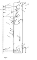
- Fig. 1 represents an elevator system applying a safety arrangement according to the invention.
- An elevator car 28 has been fitted to travel in an elevator shaft 27 from floor to floor 21, 22.
- This elevator system according to the invention also comprises a counterweight 23, but the elevator system of the invention may also be implemented without a counterweight.
- the elevator motor 25 is disposed in the elevator shaft, but it may also be placed in a machine room.
- end limit markers 12, 13, 14, 15 The extreme limits of movement of the elevator car in the elevator shaft are determined by end limit markers 12, 13, 14, 15. During normal operation, the elevator car travels between the extreme limits determined by end limit markers 12, 14. When the mechanical safety devices 10, 18, 24 have been set into their active position, the elevator can only be operated in maintenance mode within the shaft portion defined by end limit markers 13, 15. Fitted in conjunction with the elevator car are end limit marker readers 43,44. In this embodiment of the invention, the end limit markers used are ramps and the end limit marker readers are switches that can be brought into contact with the ramps.
- the electric safety controller reads switches 7,8 measuring the position of the landing doors and, via a data interface bus 6, a detector 29 measuring the position of the elevator car door. Based on the positions of these, the electric safety controller infers a transition of the safety system into the 'person in shaft' state. In this situation, operation of the elevator both in normal mode and in maintenance mode is inhibited.
- the switch 9 reading the operating state of the mechanical safety device indicates that the mechanical safety device has been reset to the working position, maintenance operation is allowed.
- the electric safety controller reads the switch indicating the state of the elevator maintenance operation unit via the data interface bus 6 and allows maintenance operation by controlling the brake 26.
- the elevator shaft is provided with two different sets of end limits to determine the extreme limits of movement of the elevator car. During normal operation, the elevator is allowed to come closer to the end, determined by the ramps 12,14. In maintenance operation mode, the extreme limits of movement are defined by ramps 13,15.
- the electric safety controller 3 reads the position of the elevator car in the elevator shaft by means of switches 43,44 and, when the elevator moves past a ramp, stops it by controlling the brake 26. The switch is opened when it comes into contact with a ramp. In this preferred embodiment of the invention, the switches are fitted in a staggered arrangement with the ramps such that switch 43 reads ramps 12 and 15 and switch 44 reads ramps 13 and 14.
- the electric safety controller prevents elevator operation in both normal and maintenance modes. If only switch 43 is open, then upward movement in maintenance operation mode is inhibited. If only switch 44 is open, then downward movement in maintenance operation mode is inhibited.
- the electric safety controller 3 additionally communicates via the data interface bus 6 with at least the elevator system controller 2, with the elevator motor controller 1 and the elevator car door controller 4.
- the electric safety controller 3 makes an inference about the operating state of the safety arrangement of the elevator. If the controller detects a functional deviation on the basis of the data it has read from the detectors, it issues a control command to the mechanical stopping device 26. In addition, it sends over the data interface bus 6 a command preventing operation to the elevator motor controller 1 and data indicating the functional deviation to the other control devices 2,4.
- the electric safety controller 3 When the electric safety controller 3 detects a 'person in shaft' state, it saves corresponding data to the non-volatile memory of the safety controller. After this, the electric safety controller can only be restored to its normal state by means of a manually operated reset mechanism 41.
- the manually operated reset mechanism In the safety arrangement according to Fig. 1 , the manually operated reset mechanism is disposed on the lowest floor in the elevator shaft, and the electric safety controller reads the state of the reset mechanism via the data interface bus 6.
- the manually operated reset mechanism 41 can also be disposed in connection with the electric safety controller, and the electric safety controller can read the state of the reset mechanism 42 via a specific separate communication bus.
- a mechanical safety device 24 is also placed on the top of the elevator car 28.
- the state of the safety device can be read by the electric safety controller 3 via the data interface bus 6.
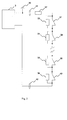
- Fig. 2 represents a set of equipment according to the invention which can be used to read the operating states of the switches 37,38,39,40 in the electric safety system. These switches are connected as a series circuit and resistors 33,34,35,36 are fitted in parallel with them.
- the series circuit is connected to the electric safety controller 3.
- the electric safety controller feeds a voltage 30 into the series circuit through a series resistor 32.
- the equipment additionally comprises means for measuring 31,42 the current flowing in the series circuit.
- the electric safety controller feeds a known voltage 30 into the series circuit through the series resistor 32.
- the switches 37,38,39,40 are closed, the current flowing in the series circuit is only limited by resistor 32.
- the current can now be measured by the measuring devices 31, 42 and the state of the series circuit can be read correspondingly.
- the current path through that switch is interrupted and the current starts flowing through the resistor fitted in parallel with the switch.
- resistor 33 the current flowing in the series circuit is reduced, because the flow of the current is limited by the series connection of resistors 32 and 33.
- the current measurement can reveal the opening of one or more switches.
- the current flowing in the series circuit is the smaller the more switches are open. In this case, however, it is not possible to identify which particular switch is open. If instead the resistors 33,34,35,36 in the series circuit are so chosen that they differ from each other in resistance value, then it is possible to identify the state of each individual switch in the series circuit. In this case, in choosing the resistors it is also necessary to consider combinations of different resistors so that the value of each single resistor should differ from the combination of a series connection of two or more different resistors to allow the state of an individual switch to be detected.
- a failure of the series circuit of the switches e.g. an earth fault.
- the current flowing into the series circuit is measured by measuring device 31 and the current returning from the series circuit to the electric safety controller by measuring device 42.
- some of the current fed into the series circuit escapes at the point of earth fault to other structural parts while only a proportion of it returns back to the electric safety controller 3 via the series circuit.
- the returning current is measured by measuring device 42, and the fault condition can be detected by comparing the current flowing out of the series circuit and the current returning into the series circuit.
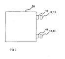
- Fig. 3 is a top view representation of an elevator car 28 according to Fig. 1 .
- the switches 43 and 44 are placed in a staggered arrangement with the ramps 12,13,14,15 in such manner that ramps 12 and 15 lie in the path of switch 43 and ramps 13 and 14 lie in the path of switch 44 as the elevator car 28 is moving in the elevator shaft.
- switch 43 can be used to read the ramp 15 in the upper part of the elevator shaft which determines the extreme limit of movement during maintenance operation and the ramp 12 in the lower part of the elevator shaft which determines the extreme limit of movement during normal operation.
- Switch 44 can similarly be used to read the ramp 14 in the upper part of the elevator shaft which determines the extreme limit of movement during normal operation and the ramp 13 in the lower part of the elevator shaft which determines the extreme limit of movement during maintenance operation.
Landscapes
- Maintenance And Inspection Apparatuses For Elevators (AREA)
- Elevator Control (AREA)
- Indicating And Signalling Devices For Elevators (AREA)
Claims (16)
- Agencement de sécurité d'ascenseur pour la mise en oeuvre d'espaces de sécurité dans une cage d'ascenseur (27), ledit agencement de sécurité comprenant un dispositif de sécurité mécanique, préférentiellement un poteau ou une barrière (10, 18, 24), qui peut être déplacé dans une position de travail pour assurer un espace de sécurité suffisant dans la cage d'ascenseur, et ledit agencement de sécurité comprenant en outre un système de sécurité électrique comprenant au moins l'équipement suivant :- en liaison avec le dispositif de sécurité mécanique (10, 18, 24), au moins un détecteur (9) pour identifier l'état de fonctionnement du dispositif de sécurité mécanique, et- en liaison avec la porte palière d'ascenseur, au moins un détecteur (7, 8, 37, 38, 39, 40) pour identifier la position de la porte palière, et- un moyen pour lire les détecteurs prévus conjointement avec la porte palière- un régulateur de sécurité électrique (3), qui lit les données depuis des dispositifs de commande d'ascenseur et qui lit en outre des données depuis des détecteurs compris dans le régulateur de sécurité électrique- un bus d'interface de données (6) entre le régulateur de sécurité électrique (3) et les dispositifs de commande d'ascenseur,
caractérisé par le fait qu'il comprend en outre :- conjointement avec la porte palière d'ascenseur, au moins un détecteur (29) pour identifier la position de la porte de cabine d'ascenseur, et- un moyen pour lire les détecteurs placés conjointement avec la porte de cabine d'ascenseur,dans lequel le régulateur de sécurité électronique, sur la base des données obtenues, commande un ou plusieurs dispositifs d'arrêt mécaniques (26) qui empêchent le mouvement de la cabine d'ascenseur (28) dans la cage d'ascenseur (27), dans lequel l'agencement de sécurité comprend deux jeux séparés de marqueurs de limite de fin (12, 13, 14, 15) pour déterminer la position de la cabine d'ascenseur, parmi lesquels marqueurs de limite de fin ceux (12, 14) qui sont situés plus près des extrémités de la cage d'ascenseur déterminent les limites extrêmes du mouvement de cabine d'ascenseur pendant le fonctionnement normal tandis que ceux (13, 15) qui sont situés plus loin des extrémités déterminent les limites extrêmes (16, 17) du mouvement de cabine d'ascenseur pendant une intervention d'entretien, et dans lequel des lecteurs (43, 44) de marqueurs de limite de fin sont prévus conjointement avec la cabine d'ascenseur, lesdits lecteurs étant reliés au régulateur de sécurité électrique (3) via le bus d'interface de données (6). - Agencement de sécurité selon la revendication 1, caractérisé par le fait que l'agencement de sécurité comprend en outre au moins l'équipement suivant :- conjointement avec une unité d'intervention d'entretien d'ascenseur (5), au moins un détecteur pour identifier l'état de commande de l'unité d'intervention d'entretien d'ascenseur.
- Agencement de sécurité selon la revendication 1 ou 2, caractérisé par le fait que l'un des dispositifs de commande d'ascenseur est un régulateur de système d'ascenseur (2), l'un des dispositifs de commande d'ascenseur est un régulateur de moteur d'ascenseur (1) et l'un des dispositifs de commande d'ascenseur est un régulateur de porte de cabine d'ascenseur (4).
- Agencement de sécurité selon l'une quelconque des revendications 1 à 3, caractérisé par le fait que les détecteurs (7, 8, 37, 38, 39, 40) prévus conjointement avec les portes palières d'ascenseur (20) sont des interrupteurs dont le contact est ouvert par commande forcée lorsque les portes palières sont ouvertes, et lesquels interrupteurs sont disposés en série sous forme de circuit en série, qui est relié au régulateur de sécurité électrique par l'intermédiaire d'une passerelle (19) pour permettre de mesurer l'état du circuit en série.
- Agencement de sécurité selon la revendication 4, caractérisé par le fait que les moyens pour lire les détecteurs prévus conjointement avec les portes palières d'ascenseur comprennent une résistance (33, 34, 35, 36) d'une valeur de résistance égale prévue en parallèle avec chaque interrupteur (7, 8, 37, 38, 39, 40) dans le circuit en série.
- Agencement de sécurité selon la revendication 4, caractérisé par le fait que les moyens pour lire les détecteurs prévus conjointement avec les portes palières d'ascenseur comprennent une résistance (33, 34, 35, 36) d'une valeur de résistance différente prévue en parallèle avec chaque interrupteur (7, 8, 37, 38, 39, 40) dans le circuit en série pour l'identification de la position de chaque interrupteur individuel.
- Agencement de sécurité selon la revendication 5 ou 6, caractérisé par le fait que la résistance susmentionnée (33, 34, 35, 36) est préférentiellement une résistance encapsulée sous film.
- Agencement de sécurité selon l'une quelconque des revendications 4 à 7, caractérisé par le fait que le régulateur de sécurité électrique (3) comprend des moyens (30, 31, 32) pour mesurer la résistance totale du circuit en série.
- Agencement de sécurité selon l'une quelconque des revendications 1 à 8, caractérisé par le fait que le régulateur de sécurité électrique (3) susmentionné est intégré conjointement avec un autre dispositif de commande du système d'ascenseur.
- Procédé de mise en oeuvre d'espaces de sécurité dans une cage d'ascenseur, caractérisé par le fait qu'un régulateur de sécurité électrique (3) comprend des moyens (30, 31, 32) pour mesurer la résistance totale d'un circuit en série et que, dans le procédé- le nombre de portes palières (20) ouvertes est lu au moyen de détecteurs (7, 8, 37, 38, 39, 40) prévus conjointement avec les portes palières (20), le nombre de portes de cabine d'ascenseur ouvertes est lu au moyen de détecteurs (29) prévus conjointement avec les portes de cabine d'ascenseur, et la position d'un dispositif de sécurité mécanique est lue au moyen de détecteurs (9) prévus conjointement avec le dispositif de sécurité mécanique (10, 18, 24)- s'il est établi que le nombre de portes palières ouvertes est supérieur au nombre de portes de cabine d'ascenseur ouvertes, alors le système de sécurité est mis dans un état 'personne dans la cage' et le fonctionnement de l'ascenseur est empêché- s'il est établi pendant l'état 'personne dans la cage' du système de sécurité que le nombre de portes palières ouvertes est égal au nombre de portes de cabine ouvertes et que le dispositif de sécurité mécanique a été mis dans une position de fonctionnement, alors une intervention d'entretien est permise.
- Procédé selon la revendication 10, caractérisé par le fait que le procédé comprend au moins l'une des étapes suivantes :- après l'entrée du système de sécurité dans l'état 'personne dans la cage', les données indiquant cette modification sont sauvegardées dans la mémoire non volatile du régulateur de sécurité électrique (3)- l'état d'un mécanisme de réinitialisation commandé manuellement (41) est lu par le régulateur de sécurité électrique (3), et lorsqu'il est détecté que le mécanisme de réinitialisation (41) a été réinitialisé dans un état d'annulation de l'inhibition du fonctionnement normal, le programme étant exécuté par le régulateur de sécurité électrique est réinitialisé de l'état 'personne dans la cage' à un état de fonctionnement permettant le fonctionnement normal et les données concernant cette modification sont sauvegardées dans la mémoire non volatile du régulateur de sécurité électrique (3)- les données indiquant la modification vers l'état 'personne dans la cage' ainsi que les données indiquant l'annulation de cet état sont envoyées via le bus d'interface de données (6) aux dispositifs de commande- les données sont lues depuis les détecteurs compris dans le système de sécurité électrique via une interface de connexion du régulateur de sécurité électrique (3) simultanément par au moins deux microcontrôleurs- les éléments de données lus par les microcontrôleurs du régulateur de sécurité électrique sont comparés entre eux et les états de fonctionnement mutuels des microcontrôleurs sont surveillés via un bus de communication entre les microcontrôleurs- s'il est découvert que les données lues depuis des détecteurs diffèrent entre les microcontrôleurs ou une situation de défaillance est découverte dans l'état de fonctionnement d'un microcontrôleur, alors le fonctionnement de l'ascenseur est empêché en actionnant au moyen de la commande de sécurité électrique (3) au moins un dispositif d'arrêt mécanique (26) et dans le même contexte une commande empêchant le fonctionnement est transmise par le régulateur de sécurité électrique (3) via le bus d'interface de données (6) au régulateur (1) du moteur d'ascenseur et les données concernant la prévention de fonctionnement sont transmises aux dispositifs de commande (2, 4).
- Procédé selon la revendication 10 ou 11, caractérisé par le fait que le régulateur de sécurité électrique (3) contient une mémoire non volatile et que le procédé comporte les étapes suivantes :- la tension de fonctionnement du régulateur de sécurité électrique est lue au moyen du régulateur de sécurité électrique (3) lui-même- lorsqu'il est découvert que la tension de fonctionnement du régulateur de sécurité électrique a chuté en dessous d'une valeur limite prédéterminée, le programme étant exécuté par le régulateur de sécurité électrique est mis dans un état où les données sont écrites dans la mémoire non volatile du régulateur de sécurité électrique (3)- ces variables du régulateur de sécurité électrique qui décrivent l'état actuel du programme exécuté par le régulateur de sécurité électrique (3) au moment de l'activation du processus d'écriture sont écrites dans la mémoire non volatile du régulateur de sécurité électrique.
- Procédé selon la revendication 10 ou 11, caractérisé par le fait que le régulateur de sécurité électrique (3) contient une mémoire non volatile et que le procédé comporte les étapes suivantes :- ces variables du programme étant exécuté par le régulateur de sécurité électrique qui décrivent l'état courant au moment en question dans le programme étant exécuté par le régulateur de sécurité électrique sont écrites dans la mémoire non volatile du régulateur de sécurité électrique à des intervalles de temps réguliers- en liaison avec chaque situation, une variable d'indice croissante pour identification ultérieure de la situation d'écriture est sauvegardée dans la mémoire non volatile du régulateur de sécurité électrique- lorsque le programme du régulateur de sécurité électrique est démarré, ces variables décrivant l'état du programme exécuté par le régulateur de sécurité électrique qui ont la plus grande valeur d'indice sont lues depuis la mémoire non volatile du régulateur de sécurité électrique.
- Procédé selon l'une quelconque des revendications 10 à 13, caractérisé par le fait que les interrupteurs (7, 8, 37, 38, 39, 40) définissant l'état des portes palières (20) sont disposés en série sous forme de circuit en série et des résistances (33, 34, 35, 36) d'égale valeur sont prévues en parallèle avec les interrupteurs et que le procédé comporte les étapes suivantes :- une tension est fournie dans le circuit en série par le régulateur de sécurité électrique à travers une résistance en série (32) raccordée à la sortie de tension (30) du régulateur de sécurité électrique- le courant circulant dans le circuit en série est mesuré- des valeurs limite R1, R2, ..., Rn sont déterminées pour le courant circulant dans le circuit en série de telle manière que R1 correspond à la valeur de courant la plus élevée et Rn à la valeur de courant la plus faible et que les valeurs limite sont définies de telle sorte qu'elles correspondent au nombre d'interrupteurs ouverts- le courant mesuré est comparé aux valeurs limite prédéterminées R1, R2,..., Rn du courant, dont la valeur limite R1 est la plus élevée- si le courant mesuré dépasse la valeur limite prédéterminée R1, il est alors déduit que tous les interrupteurs de porte palière prévus dans le circuit en série sont fermés- si le courant mesuré se situe dans la plage de variation d'une valeur limite de courant prédéterminée R2, ..., Rn, alors le nombre d'interrupteurs ouverts est déduit de telle manière que la valeur limite Rn la plus basse correspond au plus grand nombre d'interrupteurs ouverts, et lorsque la valeur du courant augmente, le nombre d'interrupteurs ouverts diminue.
- Procédé selon l'une quelconque des revendications 10 à 13, caractérisé par le fait que des résistances (33, 34, 35, 36) dont la valeur de résistance diffère les unes des autres sont prévues en parallèle avec les interrupteurs (37, 38, 39, 40) définissant l'état des portes palières (20) et que le procédé comporte les étapes suivantes :- une tension est fournie par le régulateur de sécurité électrique (3) dans le circuit en série à travers une résistance en série (31) raccordée à la sortie de tension (29) du régulateur de sécurité électrique- le courant circulant dans le circuit en série est mesuré- le courant mesuré est comparé à une valeur limite de courant prédéterminée R1, qui concerne la valeur limite de courant prédéterminée la plus élevée et laquelle valeur limite R1 correspond simultanément à une situation dans laquelle tous les interrupteurs dans le circuit en série sont fermés- le courant mesuré est comparé à des plages prédéterminées de variation de courant, chacune desdites plages indiquant l'ouverture d'un ou plusieurs interrupteurs de circuit en série correspondant à la plage de variation en question.
- Procédé selon la revendication 14 ou 15, caractérisé par le fait que le procédé comporte en outre les étapes suivantes :- le courant entrant dans le circuit en série est mesuré- le courant revenant du circuit en série est mesuré- le courant entrant dans le circuit en série et le courant revenant du circuit en série sont comparés entre eux- si les valeurs du courant entrant en circulation et du courant revenant diffèrent l'une de l'autre de plus d'une valeur limite prédéterminée, il est alors déduit que le circuit en série a subi une défaillance, le fonctionnement de l'ascenseur est empêché en actionnant au moyen du régulateur de sécurité électrique (3) au moins un dispositif d'arrêt mécanique (26) et dans le même contexte une commande d'arrêt est transmise par le régulateur de sécurité électrique (3) via le bus d'interface de données (6) au régulateur de moteur d'ascenseur (1) et les données concernant la prévention du fonctionnement sont envoyées aux dispositifs de commande (2, 4).
Priority Applications (1)
| Application Number | Priority Date | Filing Date | Title |
|---|---|---|---|
| EP20140170298 EP2772462B1 (fr) | 2007-01-03 | 2007-12-21 | Dispositif de sécurité d'ascenseur |
Applications Claiming Priority (2)
| Application Number | Priority Date | Filing Date | Title |
|---|---|---|---|
| FI20070006A FI125141B (fi) | 2007-01-03 | 2007-01-03 | Hissin turvalaite |
| PCT/FI2007/000302 WO2008081074A1 (fr) | 2007-01-03 | 2007-12-21 | Dispositif de sécurité d'ascenseur |
Related Child Applications (2)
| Application Number | Title | Priority Date | Filing Date |
|---|---|---|---|
| EP20140170298 Division EP2772462B1 (fr) | 2007-01-03 | 2007-12-21 | Dispositif de sécurité d'ascenseur |
| EP20140170298 Division-Into EP2772462B1 (fr) | 2007-01-03 | 2007-12-21 | Dispositif de sécurité d'ascenseur |
Publications (3)
| Publication Number | Publication Date |
|---|---|
| EP2099706A1 EP2099706A1 (fr) | 2009-09-16 |
| EP2099706A4 EP2099706A4 (fr) | 2013-10-02 |
| EP2099706B1 true EP2099706B1 (fr) | 2014-07-02 |
Family
ID=37745621
Family Applications (2)
| Application Number | Title | Priority Date | Filing Date |
|---|---|---|---|
| EP07858326.7A Active EP2099706B1 (fr) | 2007-01-03 | 2007-12-21 | Dispositif de sécurité d'ascenseur |
| EP20140170298 Not-in-force EP2772462B1 (fr) | 2007-01-03 | 2007-12-21 | Dispositif de sécurité d'ascenseur |
Family Applications After (1)
| Application Number | Title | Priority Date | Filing Date |
|---|---|---|---|
| EP20140170298 Not-in-force EP2772462B1 (fr) | 2007-01-03 | 2007-12-21 | Dispositif de sécurité d'ascenseur |
Country Status (6)
| Country | Link |
|---|---|
| US (2) | US7891467B2 (fr) |
| EP (2) | EP2099706B1 (fr) |
| CN (2) | CN101573284B (fr) |
| ES (2) | ES2483890T3 (fr) |
| FI (2) | FI125141B (fr) |
| WO (1) | WO2008081074A1 (fr) |
Cited By (1)
| Publication number | Priority date | Publication date | Assignee | Title |
|---|---|---|---|---|
| EP3159295B1 (fr) * | 2015-10-22 | 2024-04-17 | Otis Elevator Company | Dispositif d'alarme de service pour un système d'ascenseur |
Families Citing this family (74)
| Publication number | Priority date | Publication date | Assignee | Title |
|---|---|---|---|---|
| ES2405275T3 (es) * | 2005-09-09 | 2013-05-30 | Otis Elevator Company | Dispositivo de reposición del conmutador eléctrico de seguridad para un dispositivo de seguridad de cabina de ascensores |
| ATE481348T1 (de) | 2006-06-30 | 2010-10-15 | Otis Elevator Co | Aufzug mit einem flachen schacht und/oder einem geringen kopfraum |
| WO2008004021A1 (fr) * | 2006-06-30 | 2008-01-10 | Otis Elevator Company | Dispositif de sécurité destiné à sécuriser des espaces minimals au niveau du sommet ou du fond d'une cage d'ascenseur lors d'une inspection, et ascenseur ayant de tels dispositifs de sécurité |
| US8177034B2 (en) * | 2006-11-20 | 2012-05-15 | Mitsubishi Electric Corporation | Elevator system which controls a value of overspeed |
| FI125141B (fi) * | 2007-01-03 | 2015-06-15 | Kone Corp | Hissin turvalaite |
| US8556043B2 (en) * | 2007-12-03 | 2013-10-15 | Otis Elevator Company | Passive detection of persons in elevator hoistway |
| EP2067732A1 (fr) * | 2007-12-07 | 2009-06-10 | Inventio Ag | Système de détection de la position d'une cabine d'ascenseur |
| WO2009078088A1 (fr) * | 2007-12-17 | 2009-06-25 | Mitsubishi Electric Corporation | Dispositif élévateur |
| DE102008019195A1 (de) * | 2008-04-17 | 2009-10-29 | Beckhoff Automation Gmbh | Verfahren zum Betreiben einer Sicherheitssteuerung und Automatisierungsnetzwerk mit einer solchen Sicherheitssteuerung |
| FI120730B (fi) * | 2008-09-01 | 2010-02-15 | Kone Corp | Hissijärjestelmä sekä menetelmä hissijärjestelmän yhteydessä |
| US8552738B2 (en) * | 2008-11-27 | 2013-10-08 | Inventio Ag | Device for checking a safety circuit of an elevator |
| FI121423B (fi) * | 2009-04-23 | 2010-11-15 | Kone Corp | Hissin turvajärjestely |
| DE102009037347A1 (de) * | 2009-08-14 | 2011-02-17 | K.A. Schmersal Holding Gmbh & Co. Kg | Elektronisches Sicherheitssystem für einen Aufzug |
| JP2011063431A (ja) * | 2009-09-18 | 2011-03-31 | Toshiba Elevator Co Ltd | エレベータの安全回路 |
| US8256581B2 (en) * | 2009-09-30 | 2012-09-04 | Inventio Ag | Landing door proximity warning system |
| RU2543476C2 (ru) * | 2009-10-26 | 2015-02-27 | Инвенцио Аг | Предохранительная цепь в лифтовой установке |
| CA2778870C (fr) * | 2009-12-21 | 2018-05-08 | Inventio Ag | Surveillance d'un moyen de support et d'entrainement d'un systeme d'ascenseur |
| JP2011195205A (ja) * | 2010-03-17 | 2011-10-06 | Toshiba Elevator Co Ltd | エレベータの安全回路 |
| FI20105587A0 (fi) * | 2010-05-25 | 2010-05-25 | Kone Corp | Menetelmä hissikokoonpanon kuormituksen rajoittamiseksi sekä hissikokoonpano |
| US9128155B2 (en) * | 2010-06-02 | 2015-09-08 | Otis Elevator Company | Switch detection system |
| US8418813B2 (en) * | 2010-11-19 | 2013-04-16 | Mitsubishi Electric Research Laboratories, Inc. | Wireless communication network for transportation safety systems |
| FI122474B (fi) * | 2010-12-01 | 2012-02-15 | Kone Corp | Hissin turvakytkentä sekä menetelmä hissin turvakytkennän toiminnallisen poikkeaman tunnistamiseksi |
| EP2671836B1 (fr) | 2011-02-02 | 2021-03-24 | Mitsubishi Electric Corporation | Dispositif de contrôle de sécurité pour ascenseur |
| FI20115246A0 (fi) * | 2011-03-11 | 2011-03-11 | Kone Corp | Hissijärjestelmä |
| CN102229395B (zh) * | 2011-07-08 | 2013-01-16 | 中国矿业大学 | 一种矿用电梯多功能模拟实验系统 |
| DE102011054590B4 (de) * | 2011-10-18 | 2022-06-09 | Elgo-Electronic Gmbh & Co. Kg | Vorrichtung zur Positionserfassung einer Aufzugkabine und Verfahren zum Betreiben einer Aufzuganlage |
| EP2794450B1 (fr) | 2011-12-21 | 2022-04-06 | Otis Elevator Company | Système d'ascenseur comprenant une butée de cabine pour maintenir une hauteur libre |
| ES2568907T3 (es) * | 2012-10-30 | 2016-05-05 | Kone Corporation | Un ascensor y un método |
| TWI622548B (zh) * | 2012-12-13 | 2018-05-01 | 伊文修股份有限公司 | 用於人員輸送設備的監視裝置、人員輸送設備、以及用於監視人員輸送設備之方法 |
| ES2639128T3 (es) * | 2013-02-22 | 2017-10-25 | Kone Corporation | Método y disposición para vigilar la seguridad de un ascensor con contrapeso |
| EP2789563B1 (fr) * | 2013-04-09 | 2015-11-04 | Kone Corporation | Ascenseur ayant une chaîne de sécurité avec une connexion en série de dispositifs de commutation de sécurité |
| JP6207961B2 (ja) * | 2013-10-11 | 2017-10-04 | 株式会社日立製作所 | エレベータの安全システム |
| EP3083478B1 (fr) * | 2013-12-18 | 2022-06-08 | Inventio AG | Circuit de sécurité pour une installation d'ascenseur |
| FI125176B (fi) | 2014-01-21 | 2015-06-30 | Kone Corp | Turvalaitteistojärjestelyllä varustettu hissi |
| FI125132B (fi) | 2014-01-21 | 2015-06-15 | Kone Corp | Turvalaitejärjestelyllä varustettu hissi |
| EP3166879A1 (fr) * | 2014-07-08 | 2017-05-17 | Inventio AG | Système d'entretien d'une installation d'ascenseur |
| FI126734B (fi) * | 2014-08-11 | 2017-04-28 | Kone Corp | Paikannuslaitteisto, hissi sekä menetelmä hissikorin paikan määrittämiseksi |
| JP5793784B1 (ja) * | 2014-10-21 | 2015-10-14 | ウネベ建設株式会社 | 構造物監視装置および構造物監視方法 |
| MY185020A (en) * | 2014-12-10 | 2021-04-30 | Inventio Ag | Elevator system comprising with a safety monitoring system with a master/slave hierarchy |
| EP3034445A1 (fr) * | 2014-12-18 | 2016-06-22 | Kone Corporation | Appareil de configuration et circuit de sécurité principal pour un système d'ascenseur et système d'ascenseur |
| CN107810157B (zh) | 2015-06-30 | 2020-05-08 | 奥的斯电梯公司 | 井道中的电梯轿厢位置区域 |
| EP3328769B1 (fr) * | 2015-07-30 | 2022-03-16 | Inventio AG | Systeme de verrouillage de portes de cabine |
| WO2017041846A1 (fr) * | 2015-09-10 | 2017-03-16 | Otis Elevator Company | Appareil et procédé de détection de défaut de terre |
| EP3365260B1 (fr) * | 2015-10-22 | 2020-09-23 | Kone Corporation | Ascenseur avec agencement de sécurité et procédé de création d'un espace de travail sûr dans la partie supérieure de la cage d'ascenseur |
| EP3184477B1 (fr) * | 2015-12-22 | 2019-07-24 | KONE Corporation | Procédé et agencement pour la maintenance d'un ascenseur |
| CN105775940B (zh) * | 2016-04-03 | 2018-06-26 | 合肥博雷电子信息技术有限公司 | 一种基于物联网电梯监控系统 |
| CN107473061B (zh) | 2016-06-08 | 2020-10-16 | 奥的斯电梯公司 | 升降电梯系统的维护安全装置及其操作方法 |
| US10457522B2 (en) * | 2016-06-30 | 2019-10-29 | Otis Elevator Company | Limit switch system including first limit device and second limit device |
| EP3299325B1 (fr) | 2016-09-26 | 2020-12-09 | KONE Corporation | Detection d'impact dans une porte d'ascenseur |
| US10502786B2 (en) * | 2016-11-18 | 2019-12-10 | GM Global Technology Operations LLC | Vehicle including multiple analog switch monitoring system with simultaneous switch-state detection |
| US10233053B2 (en) * | 2017-01-25 | 2019-03-19 | Otis Elevator Company | Automatic door switch inspection |
| US10112802B2 (en) * | 2017-01-30 | 2018-10-30 | Otis Elevator Company | Elevator service person collision protection system |
| EP3357851B1 (fr) * | 2017-02-06 | 2023-08-02 | KONE Corporation | Mécanisme permettant d'améliorer la sécurité pour un système d'ascenseur |
| EP3366626B1 (fr) * | 2017-02-22 | 2021-01-06 | Otis Elevator Company | Système de sécurité d'ascenseur et procédé de surveillance d'un système d'ascenseur |
| JP6321245B1 (ja) * | 2017-03-06 | 2018-05-09 | 東芝エレベータ株式会社 | エレベータ保守作業支援システム |
| EP3401260B1 (fr) * | 2017-05-12 | 2023-08-09 | Otis Elevator Company | Systèmes d'édicule abritant un ascenseur |
| ES2817402T3 (es) | 2017-06-22 | 2021-04-07 | Otis Elevator Co | Dispositivos de seguridad del bloqueo de la puerta del dintel del ascensor |
| CN107381265A (zh) * | 2017-06-26 | 2017-11-24 | 安徽亿纵电子科技有限公司 | 一种电梯异常情况监测系统 |
| EP3434634B2 (fr) * | 2017-07-25 | 2024-07-03 | Otis Elevator Company | Dispositif de sécurité d'ascenseur |
| US10889465B2 (en) | 2017-07-31 | 2021-01-12 | Otis Elevator Company | Mechanical hoistway access control device |
| CN111295350B (zh) * | 2017-10-31 | 2021-10-08 | 因温特奥股份公司 | 用于监控人员运送设备中的对于安全关键的状态的安全监控装置以及用于运行这种安全监控装置的方法 |
| CN108069313A (zh) * | 2017-12-27 | 2018-05-25 | 比亦特网络科技(天津)有限公司 | 新型通用电梯监控及预诊断系统 |
| CN110203799B (zh) * | 2018-02-28 | 2024-02-06 | 蒂升电梯(上海)有限公司 | 一种具有封星功能的曳引机系统以及电梯系统 |
| CN108439119B (zh) * | 2018-03-16 | 2019-08-13 | 淮南矿业(集团)有限责任公司 | 一种双桥矿用提升机的控制方法及装置 |
| CN112135787B (zh) * | 2018-06-29 | 2022-10-18 | 因温特奥股份公司 | 安全切换系统以及用于在正常运行模式与检查运行模式之间切换电梯设备的方法 |
| EP3643674B1 (fr) * | 2018-10-26 | 2022-08-10 | Otis Elevator Company | Système d'ascenseur |
| US11591183B2 (en) | 2018-12-28 | 2023-02-28 | Otis Elevator Company | Enhancing elevator sensor operation for improved maintenance |
| ES2914319T3 (es) * | 2019-07-05 | 2022-06-09 | Otis Elevator Co | Ensamblaje de elevador con parada de bloqueo de contrapeso |
| WO2021083884A1 (fr) * | 2019-10-31 | 2021-05-06 | Inventio Ag | Appareil de commande mobile et procédé de télécommande d'une installation d'ascenseur |
| CN115362119B (zh) * | 2020-03-31 | 2025-05-20 | 因温特奥股份公司 | 用于对电梯设备进行安全监控的安全监控装置和方法 |
| WO2021229134A1 (fr) | 2020-05-13 | 2021-11-18 | Kone Corporation | Solution d'accès pour systèmes transporteurs |
| CN113682917B (zh) * | 2021-08-26 | 2023-04-18 | 日立电梯(中国)有限公司 | 一种电梯安全装置及其控制方法 |
| CN113933576B (zh) * | 2021-10-14 | 2023-11-10 | 北京理工大学 | 电子安全系统放电回路的非介入式电流测试方法 |
| CN217417797U (zh) * | 2022-03-14 | 2022-09-13 | 菱王电梯有限公司 | 电梯电源控制装置及电梯系统 |
Family Cites Families (32)
| Publication number | Priority date | Publication date | Assignee | Title |
|---|---|---|---|---|
| GB2084505B (en) | 1980-07-28 | 1984-05-10 | Raychem Ltd | Producing heat recoverable articles |
| US5057699A (en) * | 1989-12-20 | 1991-10-15 | Allied-Signal Inc. | Switch interface for determining position of a plurality of switches using a determined time |
| US5107964A (en) * | 1990-05-07 | 1992-04-28 | Otis Elevator Company | Separate elevator door chain |
| US5476157A (en) * | 1994-06-03 | 1995-12-19 | Todaro; Sam S. | Elevator control system with elevator hoistway operation monitoring system and method |
| FI110727B (fi) * | 1994-06-23 | 2003-03-14 | Vaisala Oyj | Sähköisesti moduloitava terminen säteilylähde |
| CN2252174Y (zh) * | 1995-06-22 | 1997-04-16 | 舒先达 | 一种电梯安全装置 |
| US5806633A (en) | 1995-12-22 | 1998-09-15 | Macuga; Henry J. | Elevator safety system incorporating false pit |
| CN2324133Y (zh) * | 1997-11-24 | 1999-06-16 | 顺德市佳顺微机控制设备有限公司 | 电梯故障检测与救援装置 |
| FI108124B (fi) * | 1998-03-18 | 2001-11-30 | Kone Corp | Hissin turvalaite |
| FR2777087B1 (fr) * | 1998-04-03 | 2000-05-05 | Otis Elevator Co | Dispositif pour localiser une panne de fermeture de porte paliere dans une installation d'ascenseur |
| US6032761A (en) * | 1998-04-27 | 2000-03-07 | Otis Elevator | Elevator hoistway terminal zone position checkpoint detection apparatus using a binary coding method for an emergency terminal speed limiting device |
| US6173814B1 (en) * | 1999-03-04 | 2001-01-16 | Otis Elevator Company | Electronic safety system for elevators having a dual redundant safety bus |
| US6223861B1 (en) * | 1999-08-30 | 2001-05-01 | Otis Elevator Company | Elevator hoistway access safety |
| SG85215A1 (en) * | 1999-10-08 | 2001-12-19 | Inventio Ag | Safety circuit for an elevator installation |
| US6452477B1 (en) * | 2000-09-06 | 2002-09-17 | Marconi Medical Systems, Inc. | High voltage low inductance circuit protection resistor |
| DE10108772A1 (de) * | 2001-02-23 | 2002-11-21 | Otis Elevator Co | Aufzugssicherheitseinrichtung |
| US6467585B1 (en) * | 2001-07-05 | 2002-10-22 | Otis Elevator Company | Wireless safety chain for elevator system |
| US7201256B2 (en) * | 2001-07-09 | 2007-04-10 | Inventio Ag | Elevator installation having a virtual protection area at the bottom and/or the top of the elevator shaft, and method for controlling the same |
| US6603398B2 (en) * | 2001-11-16 | 2003-08-05 | Otis Elevator Company | Hoistway access detection system |
| FR2842512B1 (fr) * | 2002-07-16 | 2005-07-22 | Jean Patrick Azpitarte | Systeme de securisation du fonctionnement des portes palieres d'un ascenseur |
| US7264090B2 (en) * | 2002-08-01 | 2007-09-04 | Otis Elevator Company | Elevator employing radio frequency identification devices (RFIDs) |
| JP4673574B2 (ja) * | 2003-05-07 | 2011-04-20 | インベンテイオ・アクテイエンゲゼルシヤフト | 一時的保護スペースを供給するための装置を用いたエレベータ設備、該装置の実装方法、および一時的保護スペースを供給するための方法 |
| US7097003B2 (en) * | 2003-07-21 | 2006-08-29 | The Peelle Company Ltd. | Elevator landing door broken chain safety device |
| US7350626B2 (en) * | 2004-10-20 | 2008-04-01 | Otis Elevator Company | Power-on-reset of elevator controllers |
| FI119878B (fi) * | 2005-02-04 | 2009-04-30 | Kone Corp | Järjestelmä ja menetelmä hissin turvallisuuden parantamiseksi |
| FI117797B (fi) * | 2005-04-08 | 2007-02-28 | Kone Corp | Hissijärjestelmä |
| WO2006108433A1 (fr) * | 2005-04-11 | 2006-10-19 | Otis Elevator Company | Circuit de securite pour trottoirs roulants |
| FI119231B (fi) * | 2006-12-08 | 2008-09-15 | Kone Corp | Menetelmä, järjestelmä ja ohjelmistotuote hissin turvakytkinten kunnon seuraamiseksi |
| FI125141B (fi) * | 2007-01-03 | 2015-06-15 | Kone Corp | Hissin turvalaite |
| FI20070486A7 (fi) * | 2007-01-03 | 2008-07-04 | Kone Corp | Hissin turvajärjestely |
| FI120828B (fi) * | 2007-02-21 | 2010-03-31 | Kone Corp | Elektroninen liikkeenrajoitin ja menetelmä elektronisen liikkeenrajoittimen ohjaamiseksi |
| FI121493B (fi) * | 2007-07-26 | 2010-11-30 | Kone Corp | Sähkömoottorikäyttö |
-
2007
- 2007-01-03 FI FI20070006A patent/FI125141B/fi not_active IP Right Cessation
- 2007-06-13 FI FI20070469A patent/FI20070469A0/fi not_active Application Discontinuation
- 2007-12-13 CN CN2007800491660A patent/CN101573284B/zh not_active Expired - Fee Related
- 2007-12-21 EP EP07858326.7A patent/EP2099706B1/fr active Active
- 2007-12-21 WO PCT/FI2007/000302 patent/WO2008081074A1/fr not_active Ceased
- 2007-12-21 ES ES07858326.7T patent/ES2483890T3/es active Active
- 2007-12-21 EP EP20140170298 patent/EP2772462B1/fr not_active Not-in-force
- 2007-12-21 ES ES14170298.5T patent/ES2539357T3/es active Active
- 2007-12-21 CN CN2007800492752A patent/CN101578228B/zh active Active
-
2009
- 2009-07-02 US US12/496,683 patent/US7891467B2/en active Active
-
2011
- 2011-01-25 US US13/013,452 patent/US7980363B2/en not_active Expired - Fee Related
Cited By (1)
| Publication number | Priority date | Publication date | Assignee | Title |
|---|---|---|---|---|
| EP3159295B1 (fr) * | 2015-10-22 | 2024-04-17 | Otis Elevator Company | Dispositif d'alarme de service pour un système d'ascenseur |
Also Published As
| Publication number | Publication date |
|---|---|
| ES2539357T3 (es) | 2015-06-30 |
| ES2483890T3 (es) | 2014-08-08 |
| EP2772462A1 (fr) | 2014-09-03 |
| HK1137004A1 (en) | 2010-07-16 |
| FI20070469A0 (fi) | 2007-06-13 |
| WO2008081074A1 (fr) | 2008-07-10 |
| CN101578228B (zh) | 2012-05-02 |
| CN101573284A (zh) | 2009-11-04 |
| US20110114422A1 (en) | 2011-05-19 |
| EP2772462B1 (fr) | 2015-05-20 |
| FI125141B (fi) | 2015-06-15 |
| US7891467B2 (en) | 2011-02-22 |
| EP2099706A4 (fr) | 2013-10-02 |
| CN101573284B (zh) | 2012-05-23 |
| US20090321192A1 (en) | 2009-12-31 |
| FI20070006L (fi) | 2008-07-04 |
| CN101578228A (zh) | 2009-11-11 |
| FI20070006A0 (fi) | 2007-01-03 |
| EP2099706A1 (fr) | 2009-09-16 |
| US7980363B2 (en) | 2011-07-19 |
Similar Documents
| Publication | Publication Date | Title |
|---|---|---|
| EP2099706B1 (fr) | Dispositif de sécurité d'ascenseur | |
| EP2722300B1 (fr) | Dispositif de sécurité pour ascenseur | |
| JP5516727B2 (ja) | 電子安全エレベータ | |
| CN1170757C (zh) | 电梯竖井进入的安全装置和方法 | |
| US8365873B2 (en) | Method and arrangement for preventing the unintended drifting of an elevator car | |
| CA2451333C (fr) | Installation d'ascenseur avec zone de protection virtuelle au niveau du fond et/ou du sommet de la cage d'ascenseur, et procede de commande de cette installation | |
| CN108217360B (zh) | 电梯安全系统和操作电梯系统的方法 | |
| US20230146745A1 (en) | Avoiding entrapment in an elevator | |
| US9745169B2 (en) | Safety system for an elevator, elevator system, and method for operating such a safety system | |
| HK1137004B (en) | Elevator safety device | |
| WO2013025185A1 (fr) | Détection et surveillance d'accès à la cuvette inférieure | |
| CN117623041A (zh) | 一种家用梯故障自动救援方法 | |
| HK1167381B (en) | Method and arrangement for preventing the drifting of an elevator car | |
| HK1135367B (en) | Safety arrangement of an elevator |
Legal Events
| Date | Code | Title | Description |
|---|---|---|---|
| PUAI | Public reference made under article 153(3) epc to a published international application that has entered the european phase |
Free format text: ORIGINAL CODE: 0009012 |
|
| 17P | Request for examination filed |
Effective date: 20090605 |
|
| AK | Designated contracting states |
Kind code of ref document: A1 Designated state(s): AT BE BG CH CY CZ DE DK EE ES FI FR GB GR HU IE IS IT LI LT LU LV MC MT NL PL PT RO SE SI SK TR |
|
| DAX | Request for extension of the european patent (deleted) | ||
| A4 | Supplementary search report drawn up and despatched |
Effective date: 20130902 |
|
| RIC1 | Information provided on ipc code assigned before grant |
Ipc: B66B 13/22 20060101ALI20130827BHEP Ipc: B66B 5/00 20060101AFI20130827BHEP |
|
| GRAP | Despatch of communication of intention to grant a patent |
Free format text: ORIGINAL CODE: EPIDOSNIGR1 |
|
| INTG | Intention to grant announced |
Effective date: 20140321 |
|
| GRAS | Grant fee paid |
Free format text: ORIGINAL CODE: EPIDOSNIGR3 |
|
| GRAA | (expected) grant |
Free format text: ORIGINAL CODE: 0009210 |
|
| AK | Designated contracting states |
Kind code of ref document: B1 Designated state(s): AT BE BG CH CY CZ DE DK EE ES FI FR GB GR HU IE IS IT LI LT LU LV MC MT NL PL PT RO SE SI SK TR |
|
| REG | Reference to a national code |
Ref country code: GB Ref legal event code: FG4D |
|
| REG | Reference to a national code |
Ref country code: CH Ref legal event code: EP Ref country code: AT Ref legal event code: REF Ref document number: 675812 Country of ref document: AT Kind code of ref document: T Effective date: 20140715 |
|
| REG | Reference to a national code |
Ref country code: IE Ref legal event code: FG4D |
|
| REG | Reference to a national code |
Ref country code: ES Ref legal event code: FG2A Ref document number: 2483890 Country of ref document: ES Kind code of ref document: T3 Effective date: 20140808 |
|
| REG | Reference to a national code |
Ref country code: DE Ref legal event code: R096 Ref document number: 602007037506 Country of ref document: DE Effective date: 20140814 |
|
| REG | Reference to a national code |
Ref country code: NL Ref legal event code: VDEP Effective date: 20140702 |
|
| REG | Reference to a national code |
Ref country code: LT Ref legal event code: MG4D |
|
| PG25 | Lapsed in a contracting state [announced via postgrant information from national office to epo] |
Ref country code: PT Free format text: LAPSE BECAUSE OF FAILURE TO SUBMIT A TRANSLATION OF THE DESCRIPTION OR TO PAY THE FEE WITHIN THE PRESCRIBED TIME-LIMIT Effective date: 20141103 Ref country code: BG Free format text: LAPSE BECAUSE OF FAILURE TO SUBMIT A TRANSLATION OF THE DESCRIPTION OR TO PAY THE FEE WITHIN THE PRESCRIBED TIME-LIMIT Effective date: 20141002 Ref country code: LT Free format text: LAPSE BECAUSE OF FAILURE TO SUBMIT A TRANSLATION OF THE DESCRIPTION OR TO PAY THE FEE WITHIN THE PRESCRIBED TIME-LIMIT Effective date: 20140702 Ref country code: CZ Free format text: LAPSE BECAUSE OF FAILURE TO SUBMIT A TRANSLATION OF THE DESCRIPTION OR TO PAY THE FEE WITHIN THE PRESCRIBED TIME-LIMIT Effective date: 20140702 Ref country code: SE Free format text: LAPSE BECAUSE OF FAILURE TO SUBMIT A TRANSLATION OF THE DESCRIPTION OR TO PAY THE FEE WITHIN THE PRESCRIBED TIME-LIMIT Effective date: 20140702 Ref country code: GR Free format text: LAPSE BECAUSE OF FAILURE TO SUBMIT A TRANSLATION OF THE DESCRIPTION OR TO PAY THE FEE WITHIN THE PRESCRIBED TIME-LIMIT Effective date: 20141003 Ref country code: FI Free format text: LAPSE BECAUSE OF FAILURE TO SUBMIT A TRANSLATION OF THE DESCRIPTION OR TO PAY THE FEE WITHIN THE PRESCRIBED TIME-LIMIT Effective date: 20140702 |
|
| PG25 | Lapsed in a contracting state [announced via postgrant information from national office to epo] |
Ref country code: PL Free format text: LAPSE BECAUSE OF FAILURE TO SUBMIT A TRANSLATION OF THE DESCRIPTION OR TO PAY THE FEE WITHIN THE PRESCRIBED TIME-LIMIT Effective date: 20140702 Ref country code: CY Free format text: LAPSE BECAUSE OF FAILURE TO SUBMIT A TRANSLATION OF THE DESCRIPTION OR TO PAY THE FEE WITHIN THE PRESCRIBED TIME-LIMIT Effective date: 20140702 Ref country code: LV Free format text: LAPSE BECAUSE OF FAILURE TO SUBMIT A TRANSLATION OF THE DESCRIPTION OR TO PAY THE FEE WITHIN THE PRESCRIBED TIME-LIMIT Effective date: 20140702 Ref country code: NL Free format text: LAPSE BECAUSE OF FAILURE TO SUBMIT A TRANSLATION OF THE DESCRIPTION OR TO PAY THE FEE WITHIN THE PRESCRIBED TIME-LIMIT Effective date: 20140702 Ref country code: IS Free format text: LAPSE BECAUSE OF FAILURE TO SUBMIT A TRANSLATION OF THE DESCRIPTION OR TO PAY THE FEE WITHIN THE PRESCRIBED TIME-LIMIT Effective date: 20141102 |
|
| REG | Reference to a national code |
Ref country code: DE Ref legal event code: R097 Ref document number: 602007037506 Country of ref document: DE |
|
| PG25 | Lapsed in a contracting state [announced via postgrant information from national office to epo] |
Ref country code: SK Free format text: LAPSE BECAUSE OF FAILURE TO SUBMIT A TRANSLATION OF THE DESCRIPTION OR TO PAY THE FEE WITHIN THE PRESCRIBED TIME-LIMIT Effective date: 20140702 Ref country code: RO Free format text: LAPSE BECAUSE OF FAILURE TO SUBMIT A TRANSLATION OF THE DESCRIPTION OR TO PAY THE FEE WITHIN THE PRESCRIBED TIME-LIMIT Effective date: 20140702 Ref country code: EE Free format text: LAPSE BECAUSE OF FAILURE TO SUBMIT A TRANSLATION OF THE DESCRIPTION OR TO PAY THE FEE WITHIN THE PRESCRIBED TIME-LIMIT Effective date: 20140702 Ref country code: DK Free format text: LAPSE BECAUSE OF FAILURE TO SUBMIT A TRANSLATION OF THE DESCRIPTION OR TO PAY THE FEE WITHIN THE PRESCRIBED TIME-LIMIT Effective date: 20140702 |
|
| PLBE | No opposition filed within time limit |
Free format text: ORIGINAL CODE: 0009261 |
|
| STAA | Information on the status of an ep patent application or granted ep patent |
Free format text: STATUS: NO OPPOSITION FILED WITHIN TIME LIMIT |
|
| 26N | No opposition filed |
Effective date: 20150407 |
|
| PG25 | Lapsed in a contracting state [announced via postgrant information from national office to epo] |
Ref country code: BE Free format text: LAPSE BECAUSE OF NON-PAYMENT OF DUE FEES Effective date: 20141231 |
|
| PG25 | Lapsed in a contracting state [announced via postgrant information from national office to epo] |
Ref country code: LU Free format text: LAPSE BECAUSE OF FAILURE TO SUBMIT A TRANSLATION OF THE DESCRIPTION OR TO PAY THE FEE WITHIN THE PRESCRIBED TIME-LIMIT Effective date: 20141221 |
|
| REG | Reference to a national code |
Ref country code: IE Ref legal event code: MM4A |
|
| PG25 | Lapsed in a contracting state [announced via postgrant information from national office to epo] |
Ref country code: IE Free format text: LAPSE BECAUSE OF NON-PAYMENT OF DUE FEES Effective date: 20141221 |
|
| PG25 | Lapsed in a contracting state [announced via postgrant information from national office to epo] |
Ref country code: SI Free format text: LAPSE BECAUSE OF FAILURE TO SUBMIT A TRANSLATION OF THE DESCRIPTION OR TO PAY THE FEE WITHIN THE PRESCRIBED TIME-LIMIT Effective date: 20140702 |
|
| REG | Reference to a national code |
Ref country code: FR Ref legal event code: PLFP Year of fee payment: 9 |
|
| PG25 | Lapsed in a contracting state [announced via postgrant information from national office to epo] |
Ref country code: MC Free format text: LAPSE BECAUSE OF FAILURE TO SUBMIT A TRANSLATION OF THE DESCRIPTION OR TO PAY THE FEE WITHIN THE PRESCRIBED TIME-LIMIT Effective date: 20140702 |
|
| PG25 | Lapsed in a contracting state [announced via postgrant information from national office to epo] |
Ref country code: MT Free format text: LAPSE BECAUSE OF FAILURE TO SUBMIT A TRANSLATION OF THE DESCRIPTION OR TO PAY THE FEE WITHIN THE PRESCRIBED TIME-LIMIT Effective date: 20140702 Ref country code: BE Free format text: LAPSE BECAUSE OF FAILURE TO SUBMIT A TRANSLATION OF THE DESCRIPTION OR TO PAY THE FEE WITHIN THE PRESCRIBED TIME-LIMIT Effective date: 20140702 Ref country code: TR Free format text: LAPSE BECAUSE OF FAILURE TO SUBMIT A TRANSLATION OF THE DESCRIPTION OR TO PAY THE FEE WITHIN THE PRESCRIBED TIME-LIMIT Effective date: 20140702 Ref country code: HU Free format text: LAPSE BECAUSE OF FAILURE TO SUBMIT A TRANSLATION OF THE DESCRIPTION OR TO PAY THE FEE WITHIN THE PRESCRIBED TIME-LIMIT; INVALID AB INITIO Effective date: 20071221 |
|
| REG | Reference to a national code |
Ref country code: FR Ref legal event code: PLFP Year of fee payment: 10 |
|
| REG | Reference to a national code |
Ref country code: FR Ref legal event code: PLFP Year of fee payment: 11 |
|
| PGFP | Annual fee paid to national office [announced via postgrant information from national office to epo] |
Ref country code: AT Payment date: 20201222 Year of fee payment: 14 |
|
| PGFP | Annual fee paid to national office [announced via postgrant information from national office to epo] |
Ref country code: IT Payment date: 20201222 Year of fee payment: 14 |
|
| REG | Reference to a national code |
Ref country code: AT Ref legal event code: MM01 Ref document number: 675812 Country of ref document: AT Kind code of ref document: T Effective date: 20211221 |
|
| PG25 | Lapsed in a contracting state [announced via postgrant information from national office to epo] |
Ref country code: AT Free format text: LAPSE BECAUSE OF NON-PAYMENT OF DUE FEES Effective date: 20211221 |
|
| PG25 | Lapsed in a contracting state [announced via postgrant information from national office to epo] |
Ref country code: IT Free format text: LAPSE BECAUSE OF NON-PAYMENT OF DUE FEES Effective date: 20211221 |
|
| P01 | Opt-out of the competence of the unified patent court (upc) registered |
Effective date: 20230525 |
|
| PGFP | Annual fee paid to national office [announced via postgrant information from national office to epo] |
Ref country code: GB Payment date: 20231220 Year of fee payment: 17 |
|
| PGFP | Annual fee paid to national office [announced via postgrant information from national office to epo] |
Ref country code: FR Payment date: 20231221 Year of fee payment: 17 |
|
| PGFP | Annual fee paid to national office [announced via postgrant information from national office to epo] |
Ref country code: ES Payment date: 20240126 Year of fee payment: 17 |
|
| PGFP | Annual fee paid to national office [announced via postgrant information from national office to epo] |
Ref country code: CH Payment date: 20240102 Year of fee payment: 17 |
|
| REG | Reference to a national code |
Ref country code: CH Ref legal event code: PL |
|
| GBPC | Gb: european patent ceased through non-payment of renewal fee |
Effective date: 20241221 |
|
| PG25 | Lapsed in a contracting state [announced via postgrant information from national office to epo] |
Ref country code: GB Free format text: LAPSE BECAUSE OF NON-PAYMENT OF DUE FEES Effective date: 20241221 |
|
| PG25 | Lapsed in a contracting state [announced via postgrant information from national office to epo] |
Ref country code: FR Free format text: LAPSE BECAUSE OF NON-PAYMENT OF DUE FEES Effective date: 20241231 |
|
| PG25 | Lapsed in a contracting state [announced via postgrant information from national office to epo] |
Ref country code: CH Free format text: LAPSE BECAUSE OF NON-PAYMENT OF DUE FEES Effective date: 20241231 |
|
| PGFP | Annual fee paid to national office [announced via postgrant information from national office to epo] |
Ref country code: DE Payment date: 20251211 Year of fee payment: 19 |
|
| REG | Reference to a national code |
Ref country code: ES Ref legal event code: FD2A Effective date: 20260130 |
|
| PG25 | Lapsed in a contracting state [announced via postgrant information from national office to epo] |
Ref country code: ES Free format text: LAPSE BECAUSE OF NON-PAYMENT OF DUE FEES Effective date: 20241222 |