EP2099990B1 - Mécanisme d'ouverture de porte - Google Patents
Mécanisme d'ouverture de porte Download PDFInfo
- Publication number
- EP2099990B1 EP2099990B1 EP07857020.7A EP07857020A EP2099990B1 EP 2099990 B1 EP2099990 B1 EP 2099990B1 EP 07857020 A EP07857020 A EP 07857020A EP 2099990 B1 EP2099990 B1 EP 2099990B1
- Authority
- EP
- European Patent Office
- Prior art keywords
- lock
- pressure piece
- door
- lock bolt
- receiving space
- Prior art date
- Legal status (The legal status is an assumption and is not a legal conclusion. Google has not performed a legal analysis and makes no representation as to the accuracy of the status listed.)
- Not-in-force
Links
- 230000036316 preload Effects 0.000 claims description 20
- 238000000034 method Methods 0.000 claims description 14
- 238000006073 displacement reaction Methods 0.000 claims description 11
- 230000009467 reduction Effects 0.000 claims description 6
- 238000004886 process control Methods 0.000 claims 2
- 238000007789 sealing Methods 0.000 description 10
- 238000009413 insulation Methods 0.000 description 8
- 230000002426 anti-panic effect Effects 0.000 description 5
- 230000001419 dependent effect Effects 0.000 description 5
- 238000001514 detection method Methods 0.000 description 4
- 239000000314 lubricant Substances 0.000 description 4
- 230000007246 mechanism Effects 0.000 description 4
- 230000001404 mediated effect Effects 0.000 description 4
- 230000008569 process Effects 0.000 description 4
- 230000005540 biological transmission Effects 0.000 description 3
- 230000001960 triggered effect Effects 0.000 description 3
- 238000013459 approach Methods 0.000 description 2
- 238000000576 coating method Methods 0.000 description 2
- 230000000694 effects Effects 0.000 description 2
- 230000010354 integration Effects 0.000 description 2
- 238000011144 upstream manufacturing Methods 0.000 description 2
- 230000002411 adverse Effects 0.000 description 1
- 230000004888 barrier function Effects 0.000 description 1
- 230000008859 change Effects 0.000 description 1
- 238000004891 communication Methods 0.000 description 1
- 238000013461 design Methods 0.000 description 1
- 238000011161 development Methods 0.000 description 1
- 230000018109 developmental process Effects 0.000 description 1
- 230000008030 elimination Effects 0.000 description 1
- 238000003379 elimination reaction Methods 0.000 description 1
- 230000009349 indirect transmission Effects 0.000 description 1
- 238000003780 insertion Methods 0.000 description 1
- 230000037431 insertion Effects 0.000 description 1
- 238000007689 inspection Methods 0.000 description 1
- 239000000463 material Substances 0.000 description 1
- 230000009347 mechanical transmission Effects 0.000 description 1
- 239000000565 sealant Substances 0.000 description 1
- 230000008054 signal transmission Effects 0.000 description 1
- 239000007787 solid Substances 0.000 description 1
- 230000006641 stabilisation Effects 0.000 description 1
- 238000011105 stabilization Methods 0.000 description 1
Images


Classifications
-
- E—FIXED CONSTRUCTIONS
- E05—LOCKS; KEYS; WINDOW OR DOOR FITTINGS; SAFES
- E05B—LOCKS; ACCESSORIES THEREFOR; HANDCUFFS
- E05B17/00—Accessories in connection with locks
- E05B17/0025—Devices for forcing the wing firmly against its seat or to initiate the opening of the wing
- E05B17/0029—Devices for forcing the wing firmly against its seat or to initiate the opening of the wing motor-operated
-
- E—FIXED CONSTRUCTIONS
- E05—LOCKS; KEYS; WINDOW OR DOOR FITTINGS; SAFES
- E05B—LOCKS; ACCESSORIES THEREFOR; HANDCUFFS
- E05B63/00—Locks or fastenings with special structural characteristics
- E05B63/24—Arrangements in which the fastening members which engage one another are mounted respectively on the wing and the frame and are both movable, e.g. for release by moving either of them
- E05B63/248—Arrangements in which the fastening members which engage one another are mounted respectively on the wing and the frame and are both movable, e.g. for release by moving either of them the striker being movable for latching, and pushed back by a member on the wing for unlatching, or vice versa
-
- E—FIXED CONSTRUCTIONS
- E05—LOCKS; KEYS; WINDOW OR DOOR FITTINGS; SAFES
- E05B—LOCKS; ACCESSORIES THEREFOR; HANDCUFFS
- E05B47/00—Operating or controlling locks or other fastening devices by electric or magnetic means
- E05B47/0046—Electric or magnetic means in the striker or on the frame; Operating or controlling the striker plate
Definitions
- the invention relates to a door opener with a door opener housing and with a trained for engagement with a lock latch lock receiving space.
- the invention further relates to a locking system with a door leaf-side door lock, which has at least one latch bolt, and with such a door opener with a lock latch receiving space into which the latch bolt protrudes in the closed state of the locking system.
- the invention also relates to a method for operating a locking system with such a door opener and with a door lock having at least one lock latch.
- Locking systems with a door lock and with a door opener to release the locking system are known.
- the door lock is usually installed in the door leaf or double-leaf doors in the active leaf.
- the door opener is correspondingly integrated into a door frame or double-leaf doors in the passive leaf in such a way that a Schloss fallenentriegelung the door lock can usually be triggered remotely via the door opener.
- a door opener allows a suitably equipped door to be pushed open for inspection and does not require a key or latch operation.
- Such a door opener which has already proven itself well, is for example in the EP 1 132 554 A2 disclosed.
- the door latch-side lock latch and / or latch receiving space usually has a free space or a clearance relative to the latch / latch protruding in the closed state of the door. Inaccuracies during the closing process can be compensated in this way. However, this clearance or game has a disadvantageous effect on the sealing properties of the door. In addition, a rattling of the doors is often perceived as disturbing.
- the invention is therefore an object of the invention to provide a door opener, a locking system and a method for controlling a locking system which independently of the barrier improves the heat and sound insulating properties of a door system. Due to the improved heat and sound insulation properties, however, the closing properties and the opening ability of the locking system should not be adversely affected at the same time.
- the door opener on at least one retractable into the lock trap receiving space pressure piece, wherein the pressure piece is designed to narrow the lock trap receiving space.
- the at least one pressure piece arranged on the door opener side is thus arranged to be movable in such a way that it can vary the space available for a latch bolt inserted into the latch latch receiving space or can narrow the latch latch space in order to determine the latch latch extended into the latch latch receiving space after the latch has moved into the lock latch receiving space to its "locked" position.
- the latch is thus between a protruding into the lock latch receiving space "locked” position in which a suitably equipped door can not be pressed, and an "unlocked” position in which the latch is retracted into a door lock and thus not in the lock latch receiving area protrudes, traversable.
- a scope over which, for example, a tilt-free retraction of the latch bolt is ensured in the lock latch receiving space can now be reduced by the retracting piece by retracting the pressure piece in the lock trap receiving space or at least eliminated in a direction of movement of the door.
- the retracted into the lock trap receiving space pressure piece thus determines the protruding into the lock trap receiving space lock latch in the lock trap receiving space preferably at least in the pivoting direction of the door.
- the pressure piece is for this purpose preferably a thrust part, which is inserted into the lock latch receiving space for lock latch detection, and very particularly preferably and not according to the invention, a pivot member which is pivoted into the lock latch receiving space for lock latch detection via a pivoting movement.
- Thrust parts are particularly suitable for transmitting a locking force to the pressure piece-dependent determination of the latch in Schloss fallenamfactraum.
- the invention it is thus possible to provide a clearance of the lock catch protruding into the lock catch receiving space in relation to the lock catch receiving space, so that when the door is closed, the lock catch can reliably and without tilting enter the door lock-side lock catch receiving space.
- the retractable in the lock trap receiving space pressure piece that the lock latch is detected in the lock trap receiving space is preferably retracted into the lock catch receiving space in such a manner that the pressure piece moves into the lock catch receiving space in the closing direction of the door leaf having the door lock.
- the door opener invention not only ensures a safe extension of the lock latch and thus provides an increased locking security available, but also improves the heat and sound insulation properties of the door.
- the direction of displacement of the at least one pressure piece extends transversely to the direction of movement of the lock case, and that a lock latch slide is arranged in the lock latch receiving space, which can push out the lock latch from the lock latch receiving space.
- the door opener on a flow control for controlling the at least one pressure piece.
- the sequence control thus controls the positioning of the pressure piece in the door opener.
- the sequence control in particular allows the coordination of the door opener function with the position of the pressure piece in the lock trap receiving space. This is particularly significant insofar as that in order to carry out the door opener function usually a previous release of the retracted into the lock trap receiving space pressure piece is necessary.
- the sequence control preferably comprises a pressure piece control plate and at least one control slope, wherein the pressure piece control at least one means is present, which is in functional communication with the at least one control slope.
- functional connections are to be understood as meaning especially those connections which convert the movements of the control slope into pressure element movements.
- the control plate is preferably arranged in the manner in the door opener housing, that it can be guided along a wall of the door opener housing. This arrangement is particularly space-saving and with regard to the limited arrangement space in the door opener housing thus advantageous.
- the pressure piece control plate preferably itself has at least one transmission element, which enables a mechanical transmission of movement, for example, the pressure piece control plate on the pressure piece or a movement of the pressure piece control plate in relation to the door opener housing.
- Such a transmission element is for example a control slope which, due to a control surface having a slope in relation to a component to be moved, transmits a movement to a further element in contact therewith.
- Control slopes are for example in the form of slots.
- a guide element protrudes into or through this slot. To control the movement then slides the guide element along the control slope.
- a guide element is, for example, a control pin, which can be designed in particularly low-friction embodiments with sliding coatings or rollers.
- the pressure piece is a wedge-shaped thrust member.
- a wedge-shaped thrust member allows a uniform and continuous reduction of the lock latch receiving space, so that the Andschreibrea runs particularly uniform. A determination of the protruding into the lock trap receiving space lock case thus succeeds particularly well.
- a door opener having a motor for extending and retracting the pressure piece.
- a motor-driven retraction and extension of the pressure piece allows, for example, a remote actuation of the pressure piece.
- Such a motor is for example an electric motor and in particular a DC motor. This embodiment is accordingly particularly suitable for a remote-controlled operation.
- the door opener has at least one intermediate piece, which is designed for the indirect transmission of a force caused by the at least one pressure piece and in particular by the at least one wedge-shaped thrust member or for transmitting a thrust piece outgoing pressure force, wherein the pressure piece in a space between an inner wall the lock latch receiving space and the intermediate piece is retractable.
- an intermediate piece is, for example, a plate against one side of which the pressure piece acts and whose side opposite the side of the plate faces the latch trap receiving space projecting in the lock latch.
- latch case strikes the pressure piece by inserting the thrust part in the lock trap receiving space against the intermediate piece and pushes or pushes this with the side opposite the pressure plate stop side piece against the lock latch.
- This particular embodiment enables the reduction or elimination of, for example, the thrust piece entering the lock catch receiving space and, in particular, the thrust forces caused by the wedge-shaped thrust member entering the lock retainer receiving space in relation to the latch which pushes the lock catch out of the lock catch receiving space.
- the intermediate piece allows a force selection, preferably only the forces are transmitted through the intermediate piece on the latch bolt, which determine the latch in the lock latch receiving space, so preferably act in the pivot plane of the door and perpendicular to Schloss fallenverfahrraum between retracted into the Schloss fallenarearaum and extended position of the latch on the latch.
- the intermediate piece thus makes it possible to prevent a possible pressing out of the pressure piece movement pushing out of the lock trap receiving space projecting into the latch case during the locking operation.
- Such a door opener with at least one intermediate piece is therefore particularly reliable with regard to the course of the locking process.
- Lubricant in the context of the invention are all means that reduce the friction between at least two components and in particular between pressure piece and lock latch and / or between the intermediate piece and pressure piece. This can be, for example, sliding coatings but also roles, etc.
- the lubricants allow the reduction of friction forces that occur in the pressure piece-dependent determination of the latch of the retracting into the lock latch receiving space pressure piece. As a result, a lesser amount of force is required for pressure-piece-related determination of the lock latch and the material stress is particularly low.
- This embodiment of a door opener according to the invention is thus particularly resistant to wear.
- the door opener is preferably a linear door opener.
- Linear door opener as used for example in the EP 1 132 554 A2 are characterized by their particularly robust design and their high functional reliability.
- the extension of an already known linear door opener with the pressure piece mechanism according to the invention thus combines the outstanding advantages of a linear door opener with the advantageous properties, such as with regard to sound and thermal insulation properties, the pressure piece mediated determination of the lock latch in Schloss fallenarearaum.
- the object of the invention is further by a locking system with a door leaf-side door lock, which has at least one latch bolt, and with a door opener according to the invention with a Schloss fallenmethodraum into which the latch bolt protrudes in the closed state of the locking system, wherein the locking system at least one retractable into the lock latch receiving space and has pressure piece acting on the lock latch, which reduces a lock case play of the extended latch bolt within the lock latch space, solved.
- An essential part of the locking system according to the invention is thus, inter alia, a door opener side pressure piece.
- the pressure piece which is designed such that it is in the lock latch receiving space the door opener protruding latch case acts in the closed state of the door, it is possible to determine the lock latch within the lock latch receiving space or to reduce the freedom of movement, especially in the pivoting plane of the door of the lock latch within the lock trap space.
- a locking system is advantageous because the door lock bearing door leaf is detected in relation to, for example, the frame-side door opener and thus, among other things, a rattling of the door is prevented in the closed state.
- the pressure piece mediated locking mechanism it is also possible to selectively press the door leaf in the closed state of the door against existing and in particular the frame side mounted seals. In this way, the sound and thermal insulation properties of such a locking system can be significantly improved.
- a door opener-side determination of the latch case also represents a significant protection against manipulation, since an externally obtained change the lock latch position is considerably more difficult.
- the locking system according to the invention is therefore also particularly resistant to burglary attempts.
- the locking system according to the invention thus comprises a door opener according to the invention described above. In this way, the already mentioned advantages of such a door opener can be transferred to an inventive locking system.
- the pressure piece of the locking system presses in the retracted state against the opening direction of the door leaf on the latch bolt.
- the pressure piece thus counteracts the opening movement of the door leaf.
- This embodiment is particularly advantageous in that the door or the door leaf is pressed by the pressure piece against the opening direction of the door, wherein usually especially in single-leaf doors in the Matzargen Scheme corresponding sealing means are present, against which the door leaf strikes.
- a pressure piece which presses in the retracted into the lock trap receiving space state against the opening direction of the door leaf on the latch bolt, thus causing the door leaf is ultimately pressed against the sealing means.
- the sound and heat insulation caused by the sealant is thus additionally supported by this locking system.
- the lock catch is acted upon by a normal force by the at least one pressure piece inserted into the lock catch receiving space.
- a normal force within the meaning of the invention is a force which acts perpendicular to the direction of movement of the latch from the "locked” position to the "unlocked” position and very particularly in addition to the opening direction of the door leaf on the latch.
- the invention relevant latch trapping movement thus relates to the movement of the latch of the latch in the door lock retracted position in the protruding into the lock trap receiving space of the door opener position in the closed state of the door.
- the displacement direction of the at least one pressure piece extends transversely and in particular perpendicular to the direction of movement of the latch.
- the direction of movement of the latch case relates in particular to the direction of displacement of the latch from the "locked” position to the "unlocked” position. In this way, it is particularly well ensured that the lock latch is not pushed out of the lock latch receiving space by the pressure piece movement. This effect can be increased even more by the preferred vertical orientation of the pressure piece side displacement or retraction in the lock trap receiving space in the closing direction or against the opening direction of the door.
- the pressure piece is advantageously pushed into a gap between a lock latch outer wall and an inner wall of the lock latch receiving space and more preferably in a gap, in the opening / closing direction of the door between an outer wall of the lock trap receiving space extending latch and an inner wall of the lock latch receiving space is located.
- the introduction of the pressure piece in this space ensures that the protruding into the lock trap receiving space lock latch is not pushed out of the pressure piece.
- a gap is usually provided in this area, so that the pressure piece mechanism is, among other things, transferable and applicable particularly well to a large number of door-opener types. Push movements are preferred, since these types of movement allow a particularly efficient power transmission and at the same time can be realized by particularly reliable control mechanisms.
- the pressure piece is designed to receive preloads acting on the door leaf.
- Vorlasten in the context of the invention result, inter alia, by the forces on the door leaf forces that can be caused for example by pressure differences on both sides of the door, by wind loads or especially but also by persons who press against the door leaf in the closed state.
- Particularly problematic are acting on the door leaf Pre-loads in the anti-panic area, as often caused by the preload tilting or pinching the locking elements is observed.
- a corresponding door opener with such a pressure piece is thus particularly suitable for use in the antipanic area.
- the pressure piece for Vorlasting and preload relief of a bolt is formed.
- ensuring unlockability of door locks and, in particular, self-locking door locks in the event of panic is of essential importance.
- the bolt is pressed here by the load on the door leaf preload in the extended state against a wall portion of the bolt receptacle, which is Vorlasting invention in combination with a preload relief at least one bolt particularly suitable.
- the pressure piece is in a particularly preferred embodiment with a stopper area upstream of the inner wall of the lock trap receiving space in the retracted into the lock trap receiving space the stop of the bolt in the opening direction of the door panel.
- This locking system is accordingly particularly easy to install, since the functional graduation or the functional offset of the door opener-side stop areas for the latch (pressure piece) and the bolt (bolt receiving space) is already fixed relative to each other in the relative structural arrangement of these two stop areas. Accordingly, the recording of the preload by the pressure piece to relieve the bolt in the locked state of the locking system succeeds in this embodiment particularly well.
- the object of the invention is finally achieved by a method for operating a locking system with a door opener according to the invention and with a door lock, the at least one latch
- the method comprises the steps of: i) positioning the door opener and the door lock in the locking position, ii) extending the lock latch and receiving the lock latch into the lock catch receiving space formed by the door opener latch, and III) reducing the play and locking the latch, in particular in the opening direction of the door lock comprising door leaf of the locking system in the lock latch receiving space by extending at least one pressure piece acting on the latch.
- the inventive method is thus characterized in particular by the determination of the lock latch in Schloss fallenarearaum.
- This method step makes it possible, on the one hand, to provide a lock case clearance for the safe movement of the lock latch into the "locked" position or for the unproblematic and secure picking up of the lock latch in the lock latch receiving space.
- a reproducible and sustainable positioning of the door leaf in relation to the door frame or the active leaf in relation to the inactive leaf succeeds via the pressure-piece-related determination of the latch in the lock latch receiving space.
- the inventive method thus allows a particularly reliable operation with regard to the locking safety of a locking system.
- a bolt is relieved of a preload by the extension of the pressure piece acting on the lock latch.
- This embodiment of a locking system is particularly suitable for the operation of a door in the antipanic area, since the preload relief of a bolt unlockability of the bolt, so moving the bolt from the "locked” position in the "unlocked” position, despite a preload load of Guaranteed door particularly reliable.
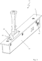
- the door opener 31 has according to the FIGS. 1 to 9 a lock plate 5, a latch 8, a DC motor 13, terminals 14, guide pins 19, a housing 32, a latch latch 33, a pressure piece 34, a lock latch receiving space 35, control plates 36 and 36 ', slots 37 and 37', a control pin 38, a lock latch recess 39, a pressure piece control plate 40, a slot 41 which is in operative engagement with the control pin 38, and a thrust pad bearing 42.
- the door opener 31 has a striking plate 5 screwed onto a housing 32.
- the striking plate 5 extends along a door frame (not shown).
- a recess is provided in housing 32, through which cables, such as for power supply and / or signal transmission to terminal 14 can be performed.
- Door leaf side is the lock plate 5, for example, a door lock (not shown) in such a way that a door lock side mounted latch 8 in the closed state of the door can intervene by the Schloss fallenausströmung 39 in the lock trap receiving space 35 of the door opener 31.
- In the castle trap reception room 35 is a lock latch slide, which can push out the lock latch 8 in the closed state of the door from the lock latch receiving space 35 in the lock direction.
- the lock trap 33 is in FIG. 1 in its retracted position and releases the lock latch receiving space 35 for engagement of the lock latch 8 (in the arrow direction).
- FIG. 2 accordingly, concerns the state of the locking system that is attached FIG. 1 connects, in which the lock latch in the direction of arrow off FIG. 1 was moved and engages in the lock trap space 35. According to FIG. 2 If the door (not shown) is closed and the lock latch 8 is in operative engagement with the lock latch receiving space 35, the door is not pressable in this locked state.
- a pressure piece 34 moves substantially against the opening direction D of the door against the latch and thus pushes the latch including door leaf in the closing direction E. In this way it is possible to suppress an existing lock case game or the freedom of movement of the latch 8 in Schloss fallenarearaum 35. Further, it is possible to press the door in the closed state in the "locked" position against a frame-side seal (not shown), for example for sound and heat insulation purposes in the closing direction E or against the opening direction D of the door leaf.
- the pressure piece 34 moves to lock latch receiving space 35 according to arrow A and proposes in relation to the latch movement laterally to the latch and ultimately pushes the latch (and thus the lock latch having door lock or the door lock having door leaf [not shown]) in the direction of the door frame (direction E) with seal.
- the pressure piece 34 thus allows to improve the sealing properties of the combined NC and locking function according to the invention.
- the pressure piece 34 is cuboid and has a homogeneous thickness.
- the pressure piece In the partial area facing the latch 8, the pressure piece has a stop area which abuts against the latch when the lock latch 8 projects into the lock latch receiving space and via which the latch side contact is mediated or which is in contact with the latch for the pressing process. This stop area is ultimately responsible for the preload recording according to the invention.
- the pressure piece 34 thus takes Vorlasten by the functionally upstream positioning in the opening direction D of the door, the door leaf on components of the locking system, in particular Latch, etc., are transferred, and derives this in the door opener 31, since the latch 8 in the opening direction D of the door first abuts against the pressure piece 34.
- a pressure piece control plate 40 is also provided, which has a control slope in the form of the slot 41 for pressure piece control.
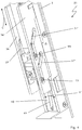
- the drive or the displacement of the control plates 36, 36 'and 40 takes place according to the FIGS. 4 and 5 via a DC motor 13 and a threaded spindle (not shown).
- the control plates 36, 36 'and 40 are U-shaped to each other, wherein for stabilization purposes, the two control plates 36 and 36' are additionally connected to each other via a bridge element.
- FIGS. 6 . 7 and 8th To open the door, a release of the pressure piece 34 and a sliding out of the lock latch 8 from the lock latch receiving space 35 is required. To illustrate this process, the latch 8 is in the FIGS. 6 . 7 and 8th not visible.
- the lock latch In the initial state according to FIG. 6 the lock latch protrudes into the lock catch receiving space 35 and is pressed by the pressure piece 34 against the opening direction of the door.
- the pressure piece 34 is for this purpose coming laterally from the inner wall of the lock trap receiving space and retracted counter to the opening direction of the door in the lock trap receiving space 35.
- the lock latch slide 33 is in its retracted position, so that the lock latch receiving space 35 is released for engagement of the lock latch 8.
- the latch by the pressure piece 34 presses by a further displacement of the control plate 36 and 36 'of the latch latch slide 33, the latch case out of the lock latch receiving space 35 or blocks this for a functional engagement of the latch 8.
- the door can now be opened by pressing.
- the exploded view according to FIG. 9 of the door opener 31 illustrates the control of the pressure piece 34.
- the pressure piece control plate 40 connects to the slot 41 at.
- the one-piece component of pressure piece 34 and pressure piece control plate 40 is arranged on the pressure pad bearing 42 movable in the door opener 31.
- FIG. 9 summarizes the movement directions for clarity and gives the mobility A 'of the pressure piece and in particular the linear movement B' of the lock latch slide 38 orthogonal to the linear movement C 'of the control plates 36 and 36' along the door frame again.
- FIGS. 7 . 8th and 9 is an unlocking indicated in chronological order, wherein the solid arrows A, B and C relate to the movements of the pressure piece 34 (arrows A), the lock latch slide 38 (arrows B) and the control plates 36 and 36 '(arrows C).
- the linear movement of the control plates 36 and 36 'according to FIG. 6 At the beginning of the unlocking operation, accordingly, first the release of the determination of the lock latch (not shown) in the lock catch receiving space 35 is controlled by the pressure piece 34. For this purpose, the pressure piece moves out of the lock catch receiving space 35.
- a locking operation is indicated in chronological order, wherein the dashed arrows A, B and C relate to the movements of the pressure piece 34 (arrows A), the lock latch slide 38 (arrows B) and the control plates 36 and 36 '(arrows C).
- the control plates 36 and 36 ' are initially moved linearly along the door frame (arrow C), so that in a orthogonal to this thrust direction linear movement (arrow B) of the lock latch slide 33 is sunk in the direction of the lock trap bottom of the lock latch receiving space 35, the lock latch receiving space 35 thus for the engagement of a latch (not shown) is released. If the movement in the direction of C of the control plates 36 and 36 'according to FIG.
Landscapes
- Physics & Mathematics (AREA)
- Electromagnetism (AREA)
- Engineering & Computer Science (AREA)
- Structural Engineering (AREA)
- Lock And Its Accessories (AREA)
Claims (17)
- Mécanisme (31) d'ouverture de porte avec un boîtier de mécanisme d'ouverture de porte et avec un espace récepteur (35) pour un pêne de serrure, configuré pour un engagement avec un pêne (8) de serrure, dans lequel
au moins un élément de pression (34) qui peut être entraîné dans l'espace récepteur (35) du pêne de serrure est prévu et configuré pour rétrécir l'espace récepteur (35) du pêne de serrure
caractérisé en ce que
la direction de déplacement dudit au moins un élément de pression (34) court transversalement à la direction de déplacement du pêne (8) de serrure, et en ce qu 'une glissière (33) du pêne de serrure est placée dans l'espace récepteur (35) du pêne de serrure, qui peut pousser le pêne (8) de serrure hors de l'espace récepteur (35) du pêne de serrure. - Mécanisme (31) d'ouverture de porte selon la revendication précédente,
caractérisé en ce que
une commande séquentielle est prévue pour guider ledit au moins un élément de pression (34). - Mécanisme (31) d'ouverture de porte selon la revendication 2,
caractérisé en ce que
la commande séquentielle comprend une plaque de guidage (40) de l'élément de pression et au moins un biseau de commande, dans lequel au moins un moyen est prévu pour guider l'élément de pression, ledit moyen étant raccordé fonctionnellement audit au moins un biseau de commande. - Mécanisme (31) d'ouverture de porte selon les revendications précédentes,
caractérisé en ce que
l'élément de pression (34) est un élément-poussoir cunéiforme. - Mécanisme (31) d'ouverture de porte selon les revendications précédentes,
caractérisé en ce que
le mécanisme d'ouverture de porte possède un moteur (13) pour engager et désengager l'élément de pression (34). - Mécanisme (31) d'ouverture de porte selon les revendications précédentes,
caractérisé en ce que
au moins un élément intermédiaire est prévu, qui est configuré pour le transfert direct d'une force produite par ledit au moins un élément de pression (34), dans lequel l'élément de pression (34) peut être engagé dans un espace intermédiaire entre la paroi intérieure de l'espace récepteur (35) du pêne de serrure et l'élément intermédiaire. - Mécanisme (31) d'ouverture de porte selon les revendications précédentes,
caractérisé en ce que
au moins un moyen coulissant est prévu pour la réduction de la friction. - Mécanisme (31) d'ouverture de porte selon les revendications précédentes,
caractérisé en ce que
le mécanisme (31) d'ouverture de porte est un mécanisme d'ouverture de porte linéaire. - Système de verrouillage avec une serrure de porte sur le côté du vantail, la serrure de porte comprenant au moins un pêne (8) de serrure, et avec un mécanisme (31) d'ouverture de porte selon l'une quelconque des revendications 1 à 8, avec un espace récepteur (35) du pêne de serrure dans lequel le pêne (8) de serrure fait saillie à l'état fermé du système de verrouillage,
caractérisé en ce que
l'élément de pression (34) est configuré de telle sorte qu'il réduise le jeu du pêne (8) de serrure engagé dans l'espace récepteur (35) du pêne de serrure. - Système de verrouillage selon la revendication 9,
caractérisé en ce que
l'élément de pression (34) fait pression sur le pêne (8) de serrure dans une direction contraire à la direction d'ouverture du vantail lorsqu'il est dans l'état engagé. - Système de verrouillage selon la revendication 9 ou 10,
caractérisé en ce que
une force normale est appliquée sur le pêne (8) de serrure par ledit au moins un élément de pression (34) engagé dans l'espace récepteur (35) du pêne de serrure à l'état fermé du système de verrouillage. - Système de verrouillage selon les revendications 9 à 11,
caractérisé en ce que
la direction de déplacement dudit au moins un élément de pression (34) est en particulier perpendiculaire à la direction de déplacement du pêne (8) de serrure. - Système de verrouillage selon les revendications 9 à 12,
caractérisé en ce que
l'élément de pression (34) est poussé dans un espace intermédiaire situé entre la paroi extérieure du pêne de serrure et une paroi intérieure de l'espace récepteur (35) du pêne de serrure de manière à réduire le jeu du pêne de serrure à l'état verrouillé du système de verrouillage. - Système de verrouillage selon les revendications 9 à 13,
caractérisé en ce que
l'élément de pression (34) est configuré pour recevoir des précharges agissant sur le vantail. - Système de verrouillage selon les revendications 9 à 14,
caractérisé en ce que
l'élément de pression (34) est configuré pour recevoir une précharge et pour réduire la précharge d'un verrou. - Système de verrouillage selon la revendication 15,
caractérisé en ce que
l'élément de pression (34) comprenant une surface de contact avec la paroi intérieure de l'espace récepteur (35) du pêne de serrure est monté en face de la surface de contact du verrou dans la direction d'ouverture du vantail lorsqu'il est à l'état engagé dans l'espace récepteur du pêne de serrure. - Procédé de mise en oeuvre d'un système de verrouillage avec un mécanisme (31) d'ouverture de porte selon au moins la revendication 1 et avec une serrure de porte comprenant au moins un pêne de serrure, le procédé comprenant les étapes suivantes :a) positionnement du mécanisme (31) d'ouverture de porte et du pêne de serrure dans une position de verrouillage ;b) extension du pêne (8) de serrure sur le côté de la serrure de porte et réception du pêne (8) de serrure sur le côté du mécanisme d'ouverture de porte dans l'espace récepteur (35) du pêne de serrure formé par le pêne du mécanisme d'ouverture de porte ;
etc) réduction du jeu du pêne (8) de serrure dans l'espace récepteur (35) du pêne de serrure par engagement d'au moins un élément de pression (34) agissant sur le pêne (8) de serrure,caractérisé en ce que
la précharge sur un verrou est réduite par l'engagement de l'élément de pression (34) agissant sur le pêne (8) de serrure.
Priority Applications (1)
| Application Number | Priority Date | Filing Date | Title |
|---|---|---|---|
| PL07857020T PL2099990T3 (pl) | 2007-01-11 | 2007-12-20 | Otwieracz drzwi |
Applications Claiming Priority (2)
| Application Number | Priority Date | Filing Date | Title |
|---|---|---|---|
| DE200710001691 DE102007001691B4 (de) | 2007-01-11 | 2007-01-11 | Türöffner |
| PCT/EP2007/011297 WO2008083826A1 (fr) | 2007-01-11 | 2007-12-20 | Mécanisme d'ouverture de porte |
Publications (2)
| Publication Number | Publication Date |
|---|---|
| EP2099990A1 EP2099990A1 (fr) | 2009-09-16 |
| EP2099990B1 true EP2099990B1 (fr) | 2018-04-11 |
Family
ID=39269222
Family Applications (1)
| Application Number | Title | Priority Date | Filing Date |
|---|---|---|---|
| EP07857020.7A Not-in-force EP2099990B1 (fr) | 2007-01-11 | 2007-12-20 | Mécanisme d'ouverture de porte |
Country Status (6)
| Country | Link |
|---|---|
| EP (1) | EP2099990B1 (fr) |
| DE (1) | DE102007001691B4 (fr) |
| ES (1) | ES2672507T3 (fr) |
| PL (1) | PL2099990T3 (fr) |
| TR (1) | TR201809207T4 (fr) |
| WO (1) | WO2008083826A1 (fr) |
Cited By (1)
| Publication number | Priority date | Publication date | Assignee | Title |
|---|---|---|---|---|
| IT202300027666A1 (it) * | 2023-12-21 | 2025-06-21 | Ninz Spa | Dispositivo per rendere possibile l'apertura di una porta |
Families Citing this family (3)
| Publication number | Priority date | Publication date | Assignee | Title |
|---|---|---|---|---|
| DE102009035737A1 (de) * | 2009-08-01 | 2011-02-03 | Assa Abloy Sicherheitstechnik Gmbh | Zuziehvorrichtung für eine Tür |
| PL2703586T3 (pl) | 2012-09-04 | 2019-03-29 | Assa Abloy Sicherheitstechnik Gmbh | Układ zamka z układem czujników do skrzydła pasywnego |
| DE102023109479A1 (de) * | 2023-04-14 | 2024-10-17 | Assa Abloy Sicherheitstechnik Gmbh | Andruckvorrichtung für eine tür oder ein fenster |
Family Cites Families (4)
| Publication number | Priority date | Publication date | Assignee | Title |
|---|---|---|---|---|
| DE208097C (fr) * | 1907-12-20 | |||
| US3758142A (en) * | 1971-08-06 | 1973-09-11 | K Gartner | Lock construction |
| EP1087079A1 (fr) * | 1999-09-23 | 2001-03-28 | Rofu AG | Gâche électrique |
| DE10011610C1 (de) * | 2000-03-10 | 2001-08-30 | Fuss Fritz Gmbh & Co | Türöffner |
-
2007
- 2007-01-11 DE DE200710001691 patent/DE102007001691B4/de not_active Expired - Fee Related
- 2007-12-20 WO PCT/EP2007/011297 patent/WO2008083826A1/fr not_active Ceased
- 2007-12-20 PL PL07857020T patent/PL2099990T3/pl unknown
- 2007-12-20 TR TR2018/09207T patent/TR201809207T4/tr unknown
- 2007-12-20 EP EP07857020.7A patent/EP2099990B1/fr not_active Not-in-force
- 2007-12-20 ES ES07857020.7T patent/ES2672507T3/es active Active
Cited By (2)
| Publication number | Priority date | Publication date | Assignee | Title |
|---|---|---|---|---|
| IT202300027666A1 (it) * | 2023-12-21 | 2025-06-21 | Ninz Spa | Dispositivo per rendere possibile l'apertura di una porta |
| WO2025134170A1 (fr) * | 2023-12-21 | 2025-06-26 | Ninz Spa | Dispositif permettant l'ouverture d'une porte |
Also Published As
| Publication number | Publication date |
|---|---|
| EP2099990A1 (fr) | 2009-09-16 |
| WO2008083826A1 (fr) | 2008-07-17 |
| PL2099990T3 (pl) | 2018-09-28 |
| DE102007001691B4 (de) | 2011-01-27 |
| ES2672507T3 (es) | 2018-06-14 |
| DE102007001691A1 (de) | 2008-07-24 |
| TR201809207T4 (tr) | 2018-07-23 |
Similar Documents
| Publication | Publication Date | Title |
|---|---|---|
| EP2037063B1 (fr) | Système de verrouillage d'une porte | |
| WO2007104499A2 (fr) | Dispositif de verrouillage pour une porte | |
| DE60127350T2 (de) | Schloss mit interner Kupplung | |
| EP2673435B1 (fr) | Système de serrure pour bloc-porte à deux vantaux à fonction anti-panique | |
| EP1692356B1 (fr) | Gache electrique | |
| EP0816603A2 (fr) | Serrure anti-panique autoverrouillante | |
| EP2099990B1 (fr) | Mécanisme d'ouverture de porte | |
| EP1056915A1 (fr) | Serrure | |
| DE19845515C2 (de) | Schließvorrichtung für ein Schloß | |
| EP2792826B1 (fr) | Verrouillage pour un battant de porte ou de fenêtre | |
| DE202009016137U1 (de) | Treibstangenschloss mit Panikfunktion und Mehrfachverriegelung | |
| DE10125915B4 (de) | Fehlbedienungssicheres Schiebeflügel- oder Schwenkflügelschloss | |
| WO2024223309A1 (fr) | Serrure | |
| DE102018115985A1 (de) | Schlossgegenkasten für ein Aktivflügelschloss mit Falzluftausgleich | |
| DE19857432B4 (de) | Schließeinrichtung für Gebäudetüren oder Gebäudefenster | |
| EP2754791B1 (fr) | Serrure de crémone | |
| DE10011610C1 (de) | Türöffner | |
| EP4206429B1 (fr) | Serrure à verrouillage automatique à déverrouillage motorisé | |
| EP4400677B1 (fr) | Serrure, notamment pour portes, avec un pêne pivotant verrouillable | |
| EP1936076B1 (fr) | Serrure anti-panique à verrouillage automatique | |
| EP2792827A2 (fr) | Verrouillage de battant de porte ou de fenêtre | |
| EP1790805B1 (fr) | Mécanisme d'actionnement à levier pour une crémone | |
| EP4717859A1 (fr) | Dispositif de verrouillage pour jardin d'enfant | |
| DE202023000829U1 (de) | Schließvorrichtung, Gegenkasten, System mit einer Schließvorrichtung und Schlossanordnung | |
| EP4624705A1 (fr) | Procédé pour actionner une serrure à pêne dormant à position centrale d'une porte à deux battants et serrure à pêne dormant à position centrale pour une porte à deux battants |
Legal Events
| Date | Code | Title | Description |
|---|---|---|---|
| PUAI | Public reference made under article 153(3) epc to a published international application that has entered the european phase |
Free format text: ORIGINAL CODE: 0009012 |
|
| 17P | Request for examination filed |
Effective date: 20090525 |
|
| AK | Designated contracting states |
Kind code of ref document: A1 Designated state(s): AT BE BG CH CY CZ DE DK EE ES FI FR GB GR HU IE IS IT LI LT LU LV MC MT NL PL PT RO SE SI SK TR |
|
| DAX | Request for extension of the european patent (deleted) | ||
| STAA | Information on the status of an ep patent application or granted ep patent |
Free format text: STATUS: EXAMINATION IS IN PROGRESS |
|
| 17Q | First examination report despatched |
Effective date: 20161222 |
|
| GRAP | Despatch of communication of intention to grant a patent |
Free format text: ORIGINAL CODE: EPIDOSNIGR1 |
|
| STAA | Information on the status of an ep patent application or granted ep patent |
Free format text: STATUS: GRANT OF PATENT IS INTENDED |
|
| INTG | Intention to grant announced |
Effective date: 20171109 |
|
| GRAS | Grant fee paid |
Free format text: ORIGINAL CODE: EPIDOSNIGR3 |
|
| GRAA | (expected) grant |
Free format text: ORIGINAL CODE: 0009210 |
|
| STAA | Information on the status of an ep patent application or granted ep patent |
Free format text: STATUS: THE PATENT HAS BEEN GRANTED |
|
| AK | Designated contracting states |
Kind code of ref document: B1 Designated state(s): AT BE BG CH CY CZ DE DK EE ES FI FR GB GR HU IE IS IT LI LT LU LV MC MT NL PL PT RO SE SI SK TR |
|
| REG | Reference to a national code |
Ref country code: GB Ref legal event code: FG4D Free format text: NOT ENGLISH |
|
| REG | Reference to a national code |
Ref country code: CH Ref legal event code: EP |
|
| REG | Reference to a national code |
Ref country code: AT Ref legal event code: REF Ref document number: 988196 Country of ref document: AT Kind code of ref document: T Effective date: 20180415 |
|
| REG | Reference to a national code |
Ref country code: CH Ref legal event code: NV Representative=s name: HEPP WENGER RYFFEL AG, CH |
|
| REG | Reference to a national code |
Ref country code: IE Ref legal event code: FG4D Free format text: LANGUAGE OF EP DOCUMENT: GERMAN |
|
| REG | Reference to a national code |
Ref country code: DE Ref legal event code: R096 Ref document number: 502007016149 Country of ref document: DE |
|
| REG | Reference to a national code |
Ref country code: NL Ref legal event code: FP |
|
| REG | Reference to a national code |
Ref country code: ES Ref legal event code: FG2A Ref document number: 2672507 Country of ref document: ES Kind code of ref document: T3 Effective date: 20180614 |
|
| REG | Reference to a national code |
Ref country code: SE Ref legal event code: TRGR |
|
| REG | Reference to a national code |
Ref country code: LT Ref legal event code: MG4D |
|
| PG25 | Lapsed in a contracting state [announced via postgrant information from national office to epo] |
Ref country code: LT Free format text: LAPSE BECAUSE OF FAILURE TO SUBMIT A TRANSLATION OF THE DESCRIPTION OR TO PAY THE FEE WITHIN THE PRESCRIBED TIME-LIMIT Effective date: 20180411 Ref country code: BG Free format text: LAPSE BECAUSE OF FAILURE TO SUBMIT A TRANSLATION OF THE DESCRIPTION OR TO PAY THE FEE WITHIN THE PRESCRIBED TIME-LIMIT Effective date: 20180711 Ref country code: FI Free format text: LAPSE BECAUSE OF FAILURE TO SUBMIT A TRANSLATION OF THE DESCRIPTION OR TO PAY THE FEE WITHIN THE PRESCRIBED TIME-LIMIT Effective date: 20180411 |
|
| PG25 | Lapsed in a contracting state [announced via postgrant information from national office to epo] |
Ref country code: GR Free format text: LAPSE BECAUSE OF FAILURE TO SUBMIT A TRANSLATION OF THE DESCRIPTION OR TO PAY THE FEE WITHIN THE PRESCRIBED TIME-LIMIT Effective date: 20180712 Ref country code: LV Free format text: LAPSE BECAUSE OF FAILURE TO SUBMIT A TRANSLATION OF THE DESCRIPTION OR TO PAY THE FEE WITHIN THE PRESCRIBED TIME-LIMIT Effective date: 20180411 |
|
| PG25 | Lapsed in a contracting state [announced via postgrant information from national office to epo] |
Ref country code: PT Free format text: LAPSE BECAUSE OF FAILURE TO SUBMIT A TRANSLATION OF THE DESCRIPTION OR TO PAY THE FEE WITHIN THE PRESCRIBED TIME-LIMIT Effective date: 20180813 |
|
| REG | Reference to a national code |
Ref country code: DE Ref legal event code: R097 Ref document number: 502007016149 Country of ref document: DE |
|
| PG25 | Lapsed in a contracting state [announced via postgrant information from national office to epo] |
Ref country code: CZ Free format text: LAPSE BECAUSE OF FAILURE TO SUBMIT A TRANSLATION OF THE DESCRIPTION OR TO PAY THE FEE WITHIN THE PRESCRIBED TIME-LIMIT Effective date: 20180411 Ref country code: RO Free format text: LAPSE BECAUSE OF FAILURE TO SUBMIT A TRANSLATION OF THE DESCRIPTION OR TO PAY THE FEE WITHIN THE PRESCRIBED TIME-LIMIT Effective date: 20180411 Ref country code: SK Free format text: LAPSE BECAUSE OF FAILURE TO SUBMIT A TRANSLATION OF THE DESCRIPTION OR TO PAY THE FEE WITHIN THE PRESCRIBED TIME-LIMIT Effective date: 20180411 Ref country code: EE Free format text: LAPSE BECAUSE OF FAILURE TO SUBMIT A TRANSLATION OF THE DESCRIPTION OR TO PAY THE FEE WITHIN THE PRESCRIBED TIME-LIMIT Effective date: 20180411 Ref country code: DK Free format text: LAPSE BECAUSE OF FAILURE TO SUBMIT A TRANSLATION OF THE DESCRIPTION OR TO PAY THE FEE WITHIN THE PRESCRIBED TIME-LIMIT Effective date: 20180411 |
|
| PLBE | No opposition filed within time limit |
Free format text: ORIGINAL CODE: 0009261 |
|
| STAA | Information on the status of an ep patent application or granted ep patent |
Free format text: STATUS: NO OPPOSITION FILED WITHIN TIME LIMIT |
|
| 26N | No opposition filed |
Effective date: 20190114 |
|
| PG25 | Lapsed in a contracting state [announced via postgrant information from national office to epo] |
Ref country code: SI Free format text: LAPSE BECAUSE OF FAILURE TO SUBMIT A TRANSLATION OF THE DESCRIPTION OR TO PAY THE FEE WITHIN THE PRESCRIBED TIME-LIMIT Effective date: 20180411 |
|
| REG | Reference to a national code |
Ref country code: SE Ref legal event code: EUG |
|
| PG25 | Lapsed in a contracting state [announced via postgrant information from national office to epo] |
Ref country code: SE Free format text: LAPSE BECAUSE OF NON-PAYMENT OF DUE FEES Effective date: 20181221 |
|
| REG | Reference to a national code |
Ref country code: NL Ref legal event code: MM Effective date: 20190101 |
|
| GBPC | Gb: european patent ceased through non-payment of renewal fee |
Effective date: 20181220 |
|
| PG25 | Lapsed in a contracting state [announced via postgrant information from national office to epo] |
Ref country code: LU Free format text: LAPSE BECAUSE OF NON-PAYMENT OF DUE FEES Effective date: 20181220 Ref country code: MC Free format text: LAPSE BECAUSE OF FAILURE TO SUBMIT A TRANSLATION OF THE DESCRIPTION OR TO PAY THE FEE WITHIN THE PRESCRIBED TIME-LIMIT Effective date: 20180411 |
|
| REG | Reference to a national code |
Ref country code: IE Ref legal event code: MM4A |
|
| PG25 | Lapsed in a contracting state [announced via postgrant information from national office to epo] |
Ref country code: NL Free format text: LAPSE BECAUSE OF NON-PAYMENT OF DUE FEES Effective date: 20190101 |
|
| REG | Reference to a national code |
Ref country code: BE Ref legal event code: MM Effective date: 20181231 |
|
| PG25 | Lapsed in a contracting state [announced via postgrant information from national office to epo] |
Ref country code: FR Free format text: LAPSE BECAUSE OF NON-PAYMENT OF DUE FEES Effective date: 20181231 Ref country code: IE Free format text: LAPSE BECAUSE OF NON-PAYMENT OF DUE FEES Effective date: 20181220 Ref country code: IT Free format text: LAPSE BECAUSE OF NON-PAYMENT OF DUE FEES Effective date: 20181220 |
|
| PG25 | Lapsed in a contracting state [announced via postgrant information from national office to epo] |
Ref country code: BE Free format text: LAPSE BECAUSE OF NON-PAYMENT OF DUE FEES Effective date: 20181231 |
|
| PG25 | Lapsed in a contracting state [announced via postgrant information from national office to epo] |
Ref country code: GB Free format text: LAPSE BECAUSE OF NON-PAYMENT OF DUE FEES Effective date: 20181220 |
|
| PG25 | Lapsed in a contracting state [announced via postgrant information from national office to epo] |
Ref country code: MT Free format text: LAPSE BECAUSE OF FAILURE TO SUBMIT A TRANSLATION OF THE DESCRIPTION OR TO PAY THE FEE WITHIN THE PRESCRIBED TIME-LIMIT Effective date: 20180411 |
|
| PG25 | Lapsed in a contracting state [announced via postgrant information from national office to epo] |
Ref country code: HU Free format text: LAPSE BECAUSE OF FAILURE TO SUBMIT A TRANSLATION OF THE DESCRIPTION OR TO PAY THE FEE WITHIN THE PRESCRIBED TIME-LIMIT; INVALID AB INITIO Effective date: 20071220 Ref country code: CY Free format text: LAPSE BECAUSE OF FAILURE TO SUBMIT A TRANSLATION OF THE DESCRIPTION OR TO PAY THE FEE WITHIN THE PRESCRIBED TIME-LIMIT Effective date: 20180411 |
|
| PG25 | Lapsed in a contracting state [announced via postgrant information from national office to epo] |
Ref country code: IS Free format text: LAPSE BECAUSE OF FAILURE TO SUBMIT A TRANSLATION OF THE DESCRIPTION OR TO PAY THE FEE WITHIN THE PRESCRIBED TIME-LIMIT Effective date: 20180811 |
|
| PGFP | Annual fee paid to national office [announced via postgrant information from national office to epo] |
Ref country code: DE Payment date: 20201208 Year of fee payment: 14 Ref country code: AT Payment date: 20201125 Year of fee payment: 14 Ref country code: CH Payment date: 20201215 Year of fee payment: 14 |
|
| PGFP | Annual fee paid to national office [announced via postgrant information from national office to epo] |
Ref country code: PL Payment date: 20201113 Year of fee payment: 14 |
|
| PGFP | Annual fee paid to national office [announced via postgrant information from national office to epo] |
Ref country code: ES Payment date: 20210108 Year of fee payment: 14 |
|
| REG | Reference to a national code |
Ref country code: DE Ref legal event code: R119 Ref document number: 502007016149 Country of ref document: DE |
|
| REG | Reference to a national code |
Ref country code: CH Ref legal event code: PL |
|
| REG | Reference to a national code |
Ref country code: AT Ref legal event code: MM01 Ref document number: 988196 Country of ref document: AT Kind code of ref document: T Effective date: 20211220 |
|
| PG25 | Lapsed in a contracting state [announced via postgrant information from national office to epo] |
Ref country code: DE Free format text: LAPSE BECAUSE OF NON-PAYMENT OF DUE FEES Effective date: 20220701 Ref country code: AT Free format text: LAPSE BECAUSE OF NON-PAYMENT OF DUE FEES Effective date: 20211220 |
|
| PG25 | Lapsed in a contracting state [announced via postgrant information from national office to epo] |
Ref country code: LI Free format text: LAPSE BECAUSE OF NON-PAYMENT OF DUE FEES Effective date: 20211231 Ref country code: CH Free format text: LAPSE BECAUSE OF NON-PAYMENT OF DUE FEES Effective date: 20211231 |
|
| REG | Reference to a national code |
Ref country code: ES Ref legal event code: FD2A Effective date: 20230224 |
|
| PG25 | Lapsed in a contracting state [announced via postgrant information from national office to epo] |
Ref country code: ES Free format text: LAPSE BECAUSE OF NON-PAYMENT OF DUE FEES Effective date: 20211221 |
|
| PG25 | Lapsed in a contracting state [announced via postgrant information from national office to epo] |
Ref country code: PL Free format text: LAPSE BECAUSE OF NON-PAYMENT OF DUE FEES Effective date: 20211220 |
|
| PG25 | Lapsed in a contracting state [announced via postgrant information from national office to epo] |
Ref country code: TR Free format text: LAPSE BECAUSE OF NON-PAYMENT OF DUE FEES Effective date: 20181220 |