EP2100064B1 - Vorrichtung zur linearen bewegung eines ventilgliedes - Google Patents
Vorrichtung zur linearen bewegung eines ventilgliedes Download PDFInfo
- Publication number
- EP2100064B1 EP2100064B1 EP08707827A EP08707827A EP2100064B1 EP 2100064 B1 EP2100064 B1 EP 2100064B1 EP 08707827 A EP08707827 A EP 08707827A EP 08707827 A EP08707827 A EP 08707827A EP 2100064 B1 EP2100064 B1 EP 2100064B1
- Authority
- EP
- European Patent Office
- Prior art keywords
- spindle
- valve member
- nut
- stop
- bearing
- Prior art date
- Legal status (The legal status is an assumption and is not a legal conclusion. Google has not performed a legal analysis and makes no representation as to the accuracy of the status listed.)
- Not-in-force
Links
Images

Classifications
-
- F—MECHANICAL ENGINEERING; LIGHTING; HEATING; WEAPONS; BLASTING
- F16—ENGINEERING ELEMENTS AND UNITS; GENERAL MEASURES FOR PRODUCING AND MAINTAINING EFFECTIVE FUNCTIONING OF MACHINES OR INSTALLATIONS; THERMAL INSULATION IN GENERAL
- F16K—VALVES; TAPS; COCKS; ACTUATING-FLOATS; DEVICES FOR VENTING OR AERATING
- F16K31/00—Actuating devices; Operating means; Releasing devices
- F16K31/44—Mechanical actuating means
- F16K31/50—Mechanical actuating means with screw-spindle or internally threaded actuating means
-
- Y—GENERAL TAGGING OF NEW TECHNOLOGICAL DEVELOPMENTS; GENERAL TAGGING OF CROSS-SECTIONAL TECHNOLOGIES SPANNING OVER SEVERAL SECTIONS OF THE IPC; TECHNICAL SUBJECTS COVERED BY FORMER USPC CROSS-REFERENCE ART COLLECTIONS [XRACs] AND DIGESTS
- Y10—TECHNICAL SUBJECTS COVERED BY FORMER USPC
- Y10T—TECHNICAL SUBJECTS COVERED BY FORMER US CLASSIFICATION
- Y10T74/00—Machine element or mechanism
- Y10T74/18—Mechanical movements
- Y10T74/18568—Reciprocating or oscillating to or from alternating rotary
- Y10T74/18576—Reciprocating or oscillating to or from alternating rotary including screw and nut
-
- Y—GENERAL TAGGING OF NEW TECHNOLOGICAL DEVELOPMENTS; GENERAL TAGGING OF CROSS-SECTIONAL TECHNOLOGIES SPANNING OVER SEVERAL SECTIONS OF THE IPC; TECHNICAL SUBJECTS COVERED BY FORMER USPC CROSS-REFERENCE ART COLLECTIONS [XRACs] AND DIGESTS
- Y10—TECHNICAL SUBJECTS COVERED BY FORMER USPC
- Y10T—TECHNICAL SUBJECTS COVERED BY FORMER US CLASSIFICATION
- Y10T74/00—Machine element or mechanism
- Y10T74/18—Mechanical movements
- Y10T74/18568—Reciprocating or oscillating to or from alternating rotary
- Y10T74/18576—Reciprocating or oscillating to or from alternating rotary including screw and nut
- Y10T74/18608—Single input split into two intermediate outputs that are subsequently superposed into a single output
-
- Y—GENERAL TAGGING OF NEW TECHNOLOGICAL DEVELOPMENTS; GENERAL TAGGING OF CROSS-SECTIONAL TECHNOLOGIES SPANNING OVER SEVERAL SECTIONS OF THE IPC; TECHNICAL SUBJECTS COVERED BY FORMER USPC CROSS-REFERENCE ART COLLECTIONS [XRACs] AND DIGESTS
- Y10—TECHNICAL SUBJECTS COVERED BY FORMER USPC
- Y10T—TECHNICAL SUBJECTS COVERED BY FORMER US CLASSIFICATION
- Y10T74/00—Machine element or mechanism
- Y10T74/18—Mechanical movements
- Y10T74/18568—Reciprocating or oscillating to or from alternating rotary
- Y10T74/18576—Reciprocating or oscillating to or from alternating rotary including screw and nut
- Y10T74/18688—Limit stop
-
- Y—GENERAL TAGGING OF NEW TECHNOLOGICAL DEVELOPMENTS; GENERAL TAGGING OF CROSS-SECTIONAL TECHNOLOGIES SPANNING OVER SEVERAL SECTIONS OF THE IPC; TECHNICAL SUBJECTS COVERED BY FORMER USPC CROSS-REFERENCE ART COLLECTIONS [XRACs] AND DIGESTS
- Y10—TECHNICAL SUBJECTS COVERED BY FORMER USPC
- Y10T—TECHNICAL SUBJECTS COVERED BY FORMER US CLASSIFICATION
- Y10T74/00—Machine element or mechanism
- Y10T74/20—Control lever and linkage systems
- Y10T74/20576—Elements
- Y10T74/20582—Levers
- Y10T74/20588—Levers toggle
Definitions
- the invention relates to a device for linear movement of a valve member.
- the invention further relates to a use of the device.
- Valve members are known.
- a valve member for an auxiliary control valve device will be described.
- a hat-shaped plate is arranged on a shaft, which is formed convex to the side facing away from the inlet valve side with a vertex.
- Such valve members are linearly moved in the direction of the longitudinal axis of the shaft depending on the operating state of the valve. This is usually done via a spindle drive, wherein the spindle and the shaft of the valve member have the same longitudinal axis. If stronger forces act on the valve member during the operating phase, the load on the spindle increases considerably, which can lead to their damage. In addition, then also higher forces act on the nuts, which are applied to the spindle, so that they can also carry damage.
- valve unit with a valve member is known in which a valve member is arranged on a push rod.
- push rod With the push rod in each case two pairs of articulated levers are connected, wherein each pair is connected to a nut arranged on a spindle.
- the articulated levers are mounted by means of rolling bearings in the nuts, wherein the rolling bearings are guided simultaneously in connecting struts.
- the connecting struts in turn are secured with tie rods, which redirect any forces occurring in the valve body.
- the invention is therefore based on the object to provide a device for the linear movement of a valve member, which remains functional even without damage when acting on the valve member suddenly higher forces.
- a device for the linear device of a valve member which consists of a rotatably mounted perpendicular to the direction of rotation spindle, which consists of a first spindle part and a second spindle part, each having opposite to each other formed external thread at on the first spindle part, a first nut with complementary internal thread and on the second spindle part, a second nut with complementary internal thread have, wherein the other end of the first connecting web and the other end of the second connecting web are rotatably mounted together on a third bearing perpendicular to the axis of rotation of the spindle, which is arranged on the stop for the valve member, wherein the direction of movement of the valve member, the center of the third Bearing and the center of the spindle in the side view always lie on a line L.
- the invention is therefore based on the object to provide a device for the linear movement of a valve member, which remains functional even without damage when acting on the valve member suddenly higher forces.
- the object is achieved in that parallel to the spindle, on its side facing away from the valve member, a stop for the first nut and the second nut is arranged, whose stop surface is perpendicular to the direction of movement of the valve member.
- the valve member is used in a valve or generally in a shut-off device.
- the first bearing and the second bearing are arranged laterally, for example, respectively on the first nut and on the second nut.
- the first connecting web and the second connecting web are, for example, a flat steel.
- the arrangement of the other end of the first connecting web and the other end of the second connecting web to a third bearing also takes place laterally on the stop for the valve member.
- the stop for the first nut and for the second nut can be made in one piece or in several parts. In normal operation, there is between the first nut and the second nut on the one hand and the stop for the first nut and the second nut on the other hand, a distance which is formed by a respective gap. The center of the spindle connects the first spindle part with the second spindle part.
- the device for the linear movement of a valve member even then undergoes no damage when acting on the valve member suddenly higher forces.
- a suddenly higher action of forces on the valve member is namely causes the spindle bends slightly and the first mother and the second nut then bear directly against the stop for the first nut and the second nut.
- the over the valve member then introduced into the device higher impact force is thus collected directly in the attack for the first nut and the second nut, so that damage to the spindle or to the first nut or on the second nut can be avoided.
- this is designed in terms of their dimensions engineering.
- the maximum impact force is assumed, which can act on the valve member during operation.
- the stop for the valve member abuts on its side facing away from the valve member on a spring element whose spring force in the direction of the linear movement of the valve member for closing or opening the valve acts on the stop.
- a spring element for example, a compression spring system is used. It is advantageous that the respective play in the bearings and in the nuts is successfully compensated by the action of the spring element, which additionally contributes to the fact that sudden force effects on the valve member to cause any damage within the device.
- the spindle is rotatably mounted in the region of its ends in each case on a first spindle bearing and on a second spindle bearing.
- the first spindle bearing and the second spindle bearing can be structurally designed so that they simultaneously serve as stops for the first nut or the second nut with the valve open.
- the spindle is advantageously fixed and increases the stability of the device.
- a further preferred embodiment of the invention provides that the center of the spindle has a larger outer diameter than the first spindle part and the second spindle part. It is advantageous that the center of the spindle can then serve as a stop for the first nut and the second nut in the closed state of the valve, which additionally improves the stability of the device.
- the invention is finally the use of the device according to the invention in poppet valves with hydraulic oil in motor vehicles.
- vibrations of the internal combustion engine can be damped depending on the speed in an advantageous manner.
- the valve member can thus be relied upon without hesitation in a linear movement when the motor vehicle, for example, passes through a pothole, which usually leads to greater impact forces acting on the valve member. Even in such cases, damage to the device can be successfully avoided.
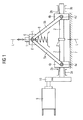
- Fig. 1 is the device for linear movement of a Valve member 1 shown in side view.
- the Device consists of a perpendicular to the direction of rotation rotatably mounted spindle 2, which consists of a first spindle part 2a and a second spindle part 2b.
- the first spindle part 2a and the second spindle part 2b each have oppositely formed external threads.
- On the first spindle part 2a is a first nut 4a with complementary internal thread
- a second nut 4b is applied with complementary internal thread.
- the first nut 4a has a first bearing 4a 'for the rotatable mounting of the one end of a first connecting web 5a perpendicular to the axis of rotation of the spindle 2.
- the second nut 4b has a second bearing 4b 'for the rotatable mounting of the one end of a second connecting web 5b perpendicular to the axis of rotation of the spindle 2.
- the other end of the first connecting web 5a and the other end of the second connecting web 5b are rotatably mounted together on a third bearing 6 'perpendicular to the axis of rotation of the spindle 2.
- the third bearing 6 ' is arranged on the stop 6 for the valve member 1.
- the direction of movement of the valve member represented by the equivalence arrow, the center of the third bearing 6 'and the center 2' of the spindle 2 are always in a side view on a line L.
- the center 2 'of the spindle 2 connects the first spindle part 2a with the second Spindle part 2b.
- a stop 7 for the first nut 4a and the second nut 4b is arranged on its, the valve member 1 side facing away from the stop surface perpendicular to the direction of movement of the valve member 1.
- the stop 6 for the valve member 1 is located on its side facing away from the valve member 1 on a spring element 8, which is designed as a compression spring system.
- the spring force of the spring element 8 acts in the direction of the linear movement of the valve member to close the valve on the stopper 6 and prevented by the respective inhibition of the game between the individual parts of the device rattling within the device during operation.
- the spindle 2 is in the region of its ends in each case at a first Spindle bearing 3a and rotatably mounted on a second spindle bearing 3b.
- the center 2 'of the spindle 2 has a larger outer diameter than the first spindle part 2a and the second spindle part 2b.
- the middle 2 can thus act as a stop for the first nut 4a and the second nut 4b.
- the spindle 2 is offset via an electric motor 9 and a downstream gear 10 in a corresponding rotational movement.
- the oppositely formed external threads on the first spindle part 2a and on the second spindle part 2b thereby the first nut 4a and the second nut 4b are moved on the spindle 2 in the direction of the center 2 ', resulting in that the valve member 1 linear is moved away from the spindle 2. This process is continued until the desired closed state of the valve is reached.
- Fig. 2 the device for linear movement of the valve member 1 in the closed state of the valve is shown in the side view.
- the first nut 4a and the second nut 4b in the closed state of the valve (not shown) not at the center 2 'of the spindle 2 at.
- Act in the now closed state of the valve abruptly greater forces on the valve member 1, this leads to a return movement of the valve member 1 in the direction of the spindle 2. If the impact forces occurring are large enough, this inevitably leads to a slight deflection of the Spindle 2.
- deflections of 0.2 mm have been realized.
Landscapes
- Engineering & Computer Science (AREA)
- General Engineering & Computer Science (AREA)
- Mechanical Engineering (AREA)
- Transmission Devices (AREA)
- Mechanically-Actuated Valves (AREA)
Description
- Die Erfindung bezieht sich auf eine Vorrichtung zur linearen Bewegung eines Ventilgliedes. Die Erfindung bezieht sich ferner auf eine Verwendung der Vorrichtung. Ventilglieder sind bekannt. In der
DE 103 27 271 A1 wird ein Ventilglied für eine Zusatzsteuerventileinrichtung beschrieben. Bei dem Ventilglied ist an einem Schaft ein hutförmiger Teller angeordnet, der zu der vom Einlassventil abgewandten Seite konvex mit einem Scheitelpunkt ausgebildet ist. Solche Ventilglieder werden in Richtung der Längsachse des Schaftes in Abhängigkeit vom Betriebszustand des Ventils linear bewegt. Dies erfolgt in der Regel über einen Spindelantrieb, wobei die Spindel und der Schaft des Ventilgliedes die selbe Längsachse aufweisen. Wirken während der Betriebsphase stärkere Kräfte auf das Ventilglied ein, so vergrößert sich die Last auf der Spindel erheblich, was zu deren Beschädigung führen kann. Darüber hinaus wirken dann auch höhere Kräfte auf die Muttern ein, die auf der Spindel aufgebracht sind, so dass auch diese Schädigungen davon tragen können. - Aus der
US 2,370,604 ist eine Ventileinheit mit einem Ventilglied bekannt, bei der ein Ventilglied an einer Schubstange angeordnet ist. Mit der Schubstange sind jeweils zwei Paare von Gelenkhebel verbunden, wobei jedes Paar mit einer auf einer Spindel angeordnete Mutter verbunden ist. Die Gelenkhebel sind mittels Wälzlager in den Muttern gelagert, wobei die Wälzlager gleichzeitig in Verbindungsstreben geführt sind. Die Verbindungsstreben ihrerseits sind mit Zugstäben gesichert, welche eventuell auftretende Kräfte in das Ventilgehäuse umleiten. - Der Erfindung liegt daher die Aufgabe zu Grunde, eine Vorrichtung zur linearen Bewegung eines Ventilgliedes zu schaffen, die ohne Schäden auch dann funktionstüchtig bleibt, wenn auf das Ventilglied schlagartig höhere Kräfte einwirken.
- Die der Erfindung zu Grunde liegende Aufgabe wird durch eine Vorrichtung zur linearen Vorrichtung eines Ventilgliedes gelöst, die aus einer senkrecht zur Bewegungsrichtung drehbar gelagerten Spindel besteht, die aus einem ersten Spindelteil und aus einem zweiten Spindelteil besteht, die jeweils gegenläufig zueinander ausgebildete Außengewinde aufweisen, bei der auf dem ersten Spindelteil eine erste Mutter mit komplementärem Innengewinde und auf dem zweiten Spindelteil eine zweite Mutter mit komplementärem Innengewinde aufweisen, wobei das andere Ende des ersten Verbindungssteges und das andere Ende des zweiten Verbindungssteges gemeinsam an einem dritten Lager senkrecht zur Drehachse der Spindel drehbar gelagert sind, das an dem Anschlag für das Ventilglied angeordnet ist, wobei die Bewegungsrichtung des Ventilgliedes, die Mitte des dritten Lagers und die Mitte der Spindel in der Seitenansicht immer auf einer Linie L liegen.
- Der Erfindung liegt daher die Aufgabe zu Grunde, eine Vorrichtung zur linearen Bewegung eines Ventilgliedes zu schaffen, die ohne Schäden auch dann funktionstüchtig bleibt, wenn auf das Ventilglied schlagartig höhere Kräfte einwirken.
- Erfindungsgemäß wird die Aufgabe dadurch gelöst, dass parallel zur Spindel, auf ihrer dem Ventilglied abgewandten Seite ein Anschlag für die erste Mutter und für die zweite Mutter angeordnet ist, deren Anschlagsfläche senkrecht zur Bewegungsrichtung des Ventilgliedes verläuft. Das Ventilglied wird in einem Ventil oder allgemein in einem Absperrorgan eingesetzt. Das erste Lager und das zweite Lager sind beispielsweise jeweils an der ersten Mutter und an der zweiten Mutter seitlich angeordnet. Bei dem ersten Verbindungssteg und dem zweiten Verbindungssteg handelt es sich beispielsweise um einen Flachstahl. Die Anordnung des anderen Endes des ersten Verbindungssteges und des anderen Endes des zweiten Verbindungssteges an einem dritten Lager erfolgt beispielsweise ebenfalls seitlich an dem Anschlag für das Ventilglied. Der Anschlag für die erste Mutter und für die zweite Mutter kann einteilig oder mehrteilig ausgeführt sein. Im Normalbetrieb besteht dabei zwischen der ersten Mutter und der zweiten Mutter einerseits und dem Anschlag für die erste Mutter und die zweite Mutter andererseits ein Abstand, der durch jeweils einen Spalt gebildet wird. Die Mitte der Spindel verbindet das erste Spindelteil mit dem zweiten Spindelteil.
- Es hat sich in überraschender Weise gezeigt, dass die Vorrichtung zur linearen Bewegung eines Ventilgliedes auch dann keinerlei Schädigungen erfährt, wenn auf das Ventilglied schlagartig höhere Kräfte einwirken. Im Falle einer schlagartig höheren Einwirkung von Kräften auf das Ventilglied wird nämlich bewirkt, dass sich die Spindel geringfügig durchbiegt und die erste Mutter sowie die zweite Mutter dann direkt am Anschlag für die erste Mutter und für die zweite Mutter anliegen. Die über das Ventilglied dann in die Vorrichtung eingebrachte höhere Stoßkraft wird somit direkt im Anschlag für die erste Mutter und für die zweite Mutter aufgefangen, so dass Schädigungen an der Spindel oder an der ersten Mutter oder an der zweiten Mutter vermieden werden können. Um die entsprechende Durchbiegung der Spindel zu gewährleisten, wird diese bezüglich ihrer Dimensionierung ingenieurmäßig ausgelegt. Dabei wird je nach dem Einsatzgebiet von der maximalen Stoßkraft ausgegangen, die im Betrieb auf das Ventilglied einwirken kann.
- Nach einer bevorzugten Ausgestaltung der Erfindung ist vorgesehen, dass der Anschlag für das Ventilglied auf seiner dem Ventilglied abgewandten Seite an einem Federelement anliegt, dessen Federkraft in Richtung der linearen Bewegung des Ventilgliedes zum Schließen oder Öffnen des Ventils auf den Anschlag wirkt. Als Federelement kommt Dabei beispielsweise ein Druckfedersystem zum Einsatz. Dabei ist vorteilhaft, dass durch die Wirkung des Federelements das jeweilige Spiel in den Lagern sowie in den Muttern erfolgreich kompensiert wird, was zusätzlich dazu beiträgt, dass schlagartige Krafteinwirkungen auf das Ventilglied zu keinerlei Schädigungen innerhalb der Vorrichtung führen.
- Gemäß einer weiteren bevorzugten Ausgestaltung der Erfindung ist die Spindel im Bereich ihrer Enden jeweils an einem ersten Spindellager und an einem zweiten Spindellager drehbar gelagert. Das erste Spindellager und das zweite Spindellager können dabei konstruktiv so ausgebildet sein, dass sie gleichzeitig als Anschläge für die erste Mutter oder die zweite Mutter bei geöffnetem Ventil dienen. Dadurch wird die Spindel vorteilhaft fixiert und die Stabilität der Vorrichtung erhöht.
- Eine weitere bevorzugte Ausgestaltung der Erfindung sieht vor, dass die Mitte der Spindel einen größeren Außendurchmesser aufweist als der erste Spindelteil und der zweite Spindelteil. Dabei ist vorteilhaft, dass die Mitte der Spindel dann als Anschlag für die erste Mutter und die zweite Mutter im geschlossenen Zustand des Ventils dienen kann, was zusätzlich die Stabilität der Vorrichtung verbessert.
- Gegenstand der Erfindung ist schließlich die Verwendung der erfindungsgemäßen Vorrichtung in Tellerventilen mit Hydrauliköl in Kraftfahrzeugen. Auf diese Weise können Schwingungen des Verbrennungsmotors drehzahlabhängig in vorteilhafter Weise gedämpft werden. Das Ventilglied kann somit auch dann bedenkenlos in eine lineare Bewegung versetzt werden, wenn das Kraftfahrzeug beispielsweise durch ein Schlagloch fährt, was in der Regel dazu führt, dass größere Stoßkräfte auf das Ventilglied einwirken. Auch in solchen Fällen können Beschädigungen an der Vorrichtung erfolgreich vermieden werden.
- Die Erfindung wird nachfolgend anhand der Zeichnung (
Fig. 1 ,Fig. 2 ) näher und beispielhaft erläutert: - Fig. 1
- zeigt die Vorrichtung zur linearen Bewegung des Ventilgliedes in der Seitenansicht im geöffneten Zustand des Ventils;
- Fig. 2
- zeigt die Vorrichtung zur linearen Bewegung des Ventilgliedes in der Seitenansicht im geschlossenen Zustand des Ventils.
- In
Fig. 1 ist die Vorrichtung zur linearen Bewegung eines Ventilgliedes 1 in der Seitenansicht dargestellt. Dabei ist das Ventilglied 1 nur schematisch dargestellt. Die Vorrichtung besteht aus einer senkrecht zur Bewegungsrichtung drehbar gelagerten Spindel 2, die aus einem ersten Spindelteil 2a und einem zweiten Spindelteil 2b besteht. Das erste Spindelteil 2a und das zweite Spindelteil 2b weisen jeweils gegenläufig zueinander ausgebildete Außengewinde auf. Auf dem ersten Spindelteil 2a ist eine erste Mutter 4a mit komplementärem Innengewinde, und auf dem zweiten Spindelteil 2b ist eine zweite Mutter 4b mit komplementärem Innengewinde aufgebracht. Die erste Mutter 4a weist ein erstes Lager 4a' für die drehbare Lagerung des einen Endes eines ersten Verbindungssteges 5a senkrecht zur Drehachse der Spindel 2 auf. Die zweite Mutter 4b weist ein zweites Lager 4b' für die drehbare Lagerung des einen Endes eines zweiten Verbindungssteges 5b senkrecht zur Drehachse der Spindel 2 auf. Das andere Ende des ersten Verbindungssteges 5a und das andere Ende des zweiten Verbindungssteges 5b sind gemeinsam an einem dritten Lager 6' senkrecht zur Drehachse der Spindel 2 drehbar gelagert. Das dritte Lager 6' ist dabei an dem Anschlag 6 für das Ventilglied 1 angeordnet. Die Bewegungsrichtung des Ventilgliedes, dargestellt durch den Äquivalenzpfeil, die Mitte des dritten Lagers 6' und die Mitte 2' der Spindel 2 liegen in der Seiteansicht immer auf einer Line L. Die Mitte 2' der Spindel 2 verbindet das erste Spindelteil 2a mit dem zweiten Spindelteil 2b. Parallel zur Spindel 2 ist auf ihrer, dem Ventilglied 1 abgewandten Seite ein Anschlag 7 für die erste Mutter 4a und die zweite Mutter 4b angeordnet, deren Anschlagfläche senkrecht zur Bewegungsrichtung des Ventilgliedes 1 verläuft. Der Anschlag 6 für das Ventilglied 1 liegt auf seiner dem Ventilglied 1 abgewandten Seite an einem Federelement 8 an, das als Druckfedersystem ausgebildet ist. Die Federkraft des Federelements 8 wirkt in Richtung der linearen Bewegung des Ventilgliedes zum Schließen des Ventils auf den Anschlag 6 und verhindert durch die jeweilige Unterbindung des Spiels zwischen den einzelnen Teilen der Vorrichtung ein Klappern innerhalb der Vorrichtung während des Betriebs. Die Spindel 2 ist im Bereich ihrer Enden jeweils an einem ersten Spindellager 3a und an einem zweiten Spindellager 3b drehbar gelagert. Die Mitte 2' der Spindel 2 weist einen größeren Außendurchmesser auf als der erste Spindelteil 2a und der zweite Spindelteil 2b. Die Mitte 2 kann somit als Anschlag für die erste Mutter 4a und die zweite Mutter 4b wirken. Ausgehend von dem inFig. 1 dargestellten geöffneten Zustand des Ventils wird die Spindel 2 über einen Elektromotor 9 und ein nachgeschaltetes Getriebe 10 in eine entsprechende Drehbewegung versetzt. In Folge der gegenläufig zueinander ausgebildeten Außengewinde auf dem ersten Spindelteil 2a beziehungsweise auf dem zweiten Spindelteil 2b werden dadurch die erste Mutter 4a und die zweite Mutter 4b auf der Spindel 2 in Richtung der Mitte 2' bewegt, was dazu führt, dass das Ventilglied 1 linear von der Spindel 2 weg bewegt wird. Dieser Vorgang wird solange fortgesetzt, bis der gewünschte geschlossene Zustand des Ventils erreicht ist. - In
Fig. 2 ist die Vorrichtung zur linearen Bewegung des Ventilgliedes 1 im geschlossenen Zustand des Ventils in der Seitenansicht dargestellt. Bei der inFig. 2 dargestellten Ausführungsform liegen die erste Mutter 4a und die zweite Mutter 4b im geschlossenen Zustand des Ventils (nicht dargestellt) nicht an der Mitte 2' der Spindel 2 an. Wirken in dem nunmehr geschlossenen Zustand des Ventils schlagartig größere Kräfte auf das Ventilglied 1 ein, so führt dies zu einer Rückbewegung des Ventilgliedes 1 in Richtung auf die Spindel 2. Sind die dabei auftretenden Stoßkräfte groß genug, so führt dies zwangsläufig zu einer geringfügigen Durchbiegung der Spindel 2. Beim Einsatz der Vorrichtung in Tellerventilen mit Hydrauliköl in Kraftfahrzeugen sind dabei beispielsweise Durchbiegungen von 0,2 mm realisiert worden. Eine solche geringfügige Durchbiegung der Spindel 2 führt dazu, dass die erste Mutter 4a und die zweite Mutter 4b zum Anschlag 7 für die erste Mutter 4a und für die zweite Mutter 4b hingedrückt werden, was durch die gestrichelten Pfeile verdeutlicht wird. Sobald die erste Mutter 4a und die zweite Mutter 4b am Anschlag 7 für die erste Mutter 4 und für die zweite Mutter 4b anliegen (nicht dargestellt) werden die Stoßkräfte in den Anschlag 7 für die erste Mutter 4a und die zweite Mutter 4b eingebracht und können dann die einzelnen Teile der Vorrichtung zur linearen Bewegung eines Ventilglieds 1 nicht mehr schädigen, wie dies beispielsweise dann der Fall wäre, wenn die Stoßkräfte von einer Spindel aufgefangen werden müsste, die zur linearen Bewegung des Ventilgliedes eingesetzt würde wobei deren Längsachse mit der Längsachse des Schaftes des Ventilgliedes identisch wäre (nicht dargestellt).
Claims (5)
- Vorrichtung zur linearen Bewegung eines Ventilgliedes (1), die aus einer senkrecht zur Bewegungsrichtung drehbar gelagerten Spindel (2) besteht, die aus einem ersten Spindelteil (2a) und aus einem zweiten Spindelteil (2b) besteht, die jeweils gegenläufig zueinander ausgebildete Außengewinde aufweisen, bei der auf dem ersten Spindelteil (2a) eine erste Mutter (4a) mit komplementärem Innengewinde und auf dem zweiten Spindelteil (2b) eine zweite Mutter (4b) mit komplementärem Innengewinde aufgebracht sind, bei der die erste Mutter (4a) ein erstes Lager (4a') für die drehbare Lagerung des einen Endes eines ersten Verbindungssteges (5a) senkrecht zur Drehachse der Spindel (2) und die zweite Mutter (4b) ein zweites Lager (4b') für die drehbare Lagerung des einen Endes eines zweiten Verbindungssteges (5b) senkrecht zur Drehachse der Spindel (2) aufweisen, wobei das andere Ende des ersten Verbindungssteges (5a) und das andere Ende des zweiten Verbindungssteges (5b) gemeinsam an einem dritten Lager (6') senkrecht zur Drehachse der Spindel (2) drehbar gelagert sind, das an dem Anschlag (6) für das Ventilglied (1) angeordnet ist, wobei die Bewegungsrichtung des Ventilgliedes (1), die Mitte des dritten Lagers (6') und die Mitte (2') der Spindel (2) in der Seitenansicht immer auf einer Linie L liegen und bei der parallel zur Spindel (2), auf ihrer, dem Ventilglied (1) abgewandten Seite ein Anschlag (7) für die erste Mutter (4a) und für die zweite Mutter (4b) angeordnet ist, deren Anschlagfläche senkrecht zur Bewegungsrichtung des Ventilgliedes (1) verläuft.
- Vorrichtung nach Anspruch 1, bei der der Anschlag (6) für das Ventilglied (1) auf seiner dem Ventilglied (1) abgewandten Seite an einem Federelement (8) anliegt, dessen Federkraft in Richtung der linearen Bewegung des Ventilgliedes (1) zum Schließen oder Öffnen des Ventils auf den Anschlag (6) wirkt.
- Vorrichtung nach Anspruch 1 oder Anspruch 2, bei der die Spindel (2) im Bereich ihrer Enden jeweils an einem ersten Spindellager (3a) und an einem zweiten Spindellager (3b) drehbar gelagert ist.
- Vorrichtung nach einem der Ansprüche 1 bis 3, bei der die Mitte (2') der Spindel (2) einen größeren Außendurchmesser aufweist als der erste Spindelteil (2a) und der zweite Spindelteil (2b).
- Verwendung der Vorrichtung nach einem der vorhergehenden Ansprüche zur linearen Bewegung von Ventilgliedern (1) in Tellerventilen mit Hydraulikölen in Kraftfahrzeugen.
Applications Claiming Priority (2)
| Application Number | Priority Date | Filing Date | Title |
|---|---|---|---|
| DE102007001741A DE102007001741A1 (de) | 2007-01-11 | 2007-01-11 | Vorrichtung zur linearen Bewegung eines Ventilgliedes |
| PCT/EP2008/050060 WO2008084012A1 (de) | 2007-01-11 | 2008-01-04 | Vorrichtung zur linearen bewegung eines ventilgliedes |
Publications (2)
| Publication Number | Publication Date |
|---|---|
| EP2100064A1 EP2100064A1 (de) | 2009-09-16 |
| EP2100064B1 true EP2100064B1 (de) | 2012-09-19 |
Family
ID=39156505
Family Applications (1)
| Application Number | Title | Priority Date | Filing Date |
|---|---|---|---|
| EP08707827A Not-in-force EP2100064B1 (de) | 2007-01-11 | 2008-01-04 | Vorrichtung zur linearen bewegung eines ventilgliedes |
Country Status (6)
| Country | Link |
|---|---|
| US (1) | US8240637B2 (de) |
| EP (1) | EP2100064B1 (de) |
| JP (1) | JP5183641B2 (de) |
| CN (1) | CN101589257B (de) |
| DE (1) | DE102007001741A1 (de) |
| WO (1) | WO2008084012A1 (de) |
Families Citing this family (5)
| Publication number | Priority date | Publication date | Assignee | Title |
|---|---|---|---|---|
| EP2267346A1 (de) * | 2009-06-19 | 2010-12-29 | RMG Regel + Messtechnik GmbH | Gasarmatur |
| GB201006099D0 (en) * | 2010-04-13 | 2010-05-26 | Airbus Operations Ltd | Slat support assembly |
| CN102381557B (zh) * | 2010-08-30 | 2013-08-28 | 鸿富锦精密工业(深圳)有限公司 | 物件分离与合并装置 |
| US9765865B2 (en) * | 2013-02-07 | 2017-09-19 | Medinol Ltd. | Variable linear motor |
| CN107990091A (zh) * | 2017-10-20 | 2018-05-04 | 江苏今达纺织实业有限公司 | 一种具备固定装置的纺织设备 |
Family Cites Families (25)
| Publication number | Priority date | Publication date | Assignee | Title |
|---|---|---|---|---|
| US535614A (en) * | 1895-03-12 | Fire-hydrant | ||
| US916218A (en) * | 1907-07-12 | 1909-03-23 | Pittsburgh Valve Foundry And Construction Company | Non-return valve. |
| US1658445A (en) * | 1923-12-11 | 1928-02-07 | Schutte & Koerting Co | Emergency closing means for boiler nonreturn valves |
| US2092926A (en) * | 1933-08-30 | 1937-09-14 | North American Car Corp | Liquid container and means for loading and unloading the same |
| DE647981C (de) * | 1936-04-01 | 1937-07-17 | Schaeffer & Budenberg G M B H | Aus zwei Absperrorganen bestehende Vorrichtung |
| US2354987A (en) * | 1942-01-19 | 1944-08-01 | Crane Co | Toggle operated valve |
| US2344594A (en) * | 1942-01-23 | 1944-03-21 | Crane Co | Motor operated toggle valve |
| US2370604A (en) * | 1944-03-02 | 1945-02-27 | Crane Co | Valve actuating means |
| US2515498A (en) * | 1945-07-16 | 1950-07-18 | Crane Co | Toggle operating mechanism for valves |
| US2603102A (en) * | 1946-11-15 | 1952-07-15 | Hobbs James Clarence | Valve closure means |
| US2757554A (en) * | 1952-08-01 | 1956-08-07 | Gen Electric | Power actuator for doors |
| GB841699A (en) * | 1956-03-31 | 1960-07-20 | Tesla Np | Vacuum pump inlet valve |
| JPS5726239Y2 (de) * | 1977-07-26 | 1982-06-07 | ||
| US4206900A (en) * | 1977-08-01 | 1980-06-10 | Borg-Warner Corporation | Valve operator |
| JPS5427300A (en) | 1977-08-01 | 1979-03-01 | Suteiga Ab | Device for shooting hydraulically bullet and piston therefor |
| US4285493A (en) * | 1979-03-01 | 1981-08-25 | Borg-Warner Corporation | Valve operator |
| JPS5937385A (ja) | 1982-08-26 | 1984-02-29 | Kurimoto Iron Works Ltd | 弁の駆動装置 |
| DE8612452U1 (de) * | 1986-05-06 | 1986-06-26 | Müller, Fritz, 7118 Ingelfingen | Elektromotorisch angetriebene Schwenkvorrichtung |
| US5196185A (en) * | 1989-09-11 | 1993-03-23 | Micro-Collagen Pharmaceutics, Ltd. | Collagen-based wound dressing and method for applying same |
| DE20018564U1 (de) * | 2000-10-30 | 2002-03-21 | CAMERON GmbH, 29227 Celle | Betätigungsvorrichtung |
| CN2572148Y (zh) * | 2002-08-23 | 2003-09-10 | 黄彪 | 活动塞阀门 |
| DE10327271A1 (de) | 2003-06-17 | 2005-02-24 | Siemens Ag | Ventilglied für eine Zusatzsteuerventileinrichtung |
| US6969048B2 (en) * | 2003-06-17 | 2005-11-29 | Siemens Aktiengesellschaft | Valve element for supplementary control valve device |
| US7097148B2 (en) * | 2004-07-21 | 2006-08-29 | Battelle Energy Alliance, Llc | Scissor thrust valve actuator |
| US8104710B2 (en) * | 2007-04-25 | 2012-01-31 | Goodrich Actuation Systems Limited | Actuator arrangement |
-
2007
- 2007-01-11 DE DE102007001741A patent/DE102007001741A1/de not_active Withdrawn
-
2008
- 2008-01-04 JP JP2009545161A patent/JP5183641B2/ja not_active Expired - Fee Related
- 2008-01-04 WO PCT/EP2008/050060 patent/WO2008084012A1/de not_active Ceased
- 2008-01-04 CN CN2008800021848A patent/CN101589257B/zh not_active Expired - Fee Related
- 2008-01-04 EP EP08707827A patent/EP2100064B1/de not_active Not-in-force
- 2008-01-04 US US12/522,874 patent/US8240637B2/en not_active Expired - Fee Related
Also Published As
| Publication number | Publication date |
|---|---|
| EP2100064A1 (de) | 2009-09-16 |
| CN101589257B (zh) | 2011-01-19 |
| DE102007001741A1 (de) | 2008-07-17 |
| WO2008084012A1 (de) | 2008-07-17 |
| US8240637B2 (en) | 2012-08-14 |
| US20100096575A1 (en) | 2010-04-22 |
| JP5183641B2 (ja) | 2013-04-17 |
| JP2010515865A (ja) | 2010-05-13 |
| CN101589257A (zh) | 2009-11-25 |
Similar Documents
| Publication | Publication Date | Title |
|---|---|---|
| EP2100064B1 (de) | Vorrichtung zur linearen bewegung eines ventilgliedes | |
| DE19964436B4 (de) | Drehtürantrieb | |
| DE102015108228A1 (de) | Vorrichtung zum Verbinden eines Kupplungsschafts mit einem Wagenkasten eines spurgeführten Fahrzeuges | |
| DE102007000943B4 (de) | Verriegelungseinrichtung für eine Welle eines Lenksystems | |
| EP1963600B1 (de) | Bowdenzuganordnung für ein kraftfahrzeugtürschloss | |
| DE102020003107A1 (de) | Abbremsvorrichtung für verstellbare Pleuel | |
| EP0942863B1 (de) | Dämpferventilanordnung | |
| EP1111227A2 (de) | Abgasrückführventil | |
| DE10203384A1 (de) | Servolenksystem | |
| DE102011012311A1 (de) | Elektromechanische Lenkung | |
| WO2006122603A1 (de) | Lenkgetriebe | |
| EP2014538A2 (de) | Schieberventil für eine hydraulische Servolenkung | |
| DE102021115777A1 (de) | Aktuator für eine Hinterachslenkung eines Fahrzeugs sowie Hinterachslenkung mit einem solchen Aktuator | |
| DE102012015181A1 (de) | Lenkgetriebe für ein Kraftfahrzeug | |
| DE102017212073A1 (de) | Zahnstangengetriebe für ein Kraftfahrzeug | |
| EP2222531B1 (de) | Servoventil für eine hydraulische servolenkung | |
| DE202005018390U1 (de) | Ventilvorrichtung für eine hydraulische Servolenkung | |
| DE102020102212A1 (de) | Aktuator | |
| DE202004006294U1 (de) | Hydraulisches Servolenkventil mit Lenkmomentüberlagerung | |
| WO1994000328A1 (de) | Drehschieberventil für hilfskraftlenkungen von kraftfahrzeugen | |
| DE1906461C3 (de) | Hydraulische Bremsdruck Regel einrichtung für Fahrzeuge mit Einzel radaufhängung | |
| EP3927997B1 (de) | Kugelgewindetrieb mit verdrehsicherung | |
| DE102005002606B4 (de) | Vorrichtung zum Andrücken einer Zahnstange an ein mit der Zahnstange in Eingriff stehendes Ritzel | |
| EP3835621B1 (de) | Stellantrieb | |
| DE102005018308A1 (de) | Hydraulisches Servolenkventil mit Lenkmomentüberlagerung |
Legal Events
| Date | Code | Title | Description |
|---|---|---|---|
| PUAI | Public reference made under article 153(3) epc to a published international application that has entered the european phase |
Free format text: ORIGINAL CODE: 0009012 |
|
| 17P | Request for examination filed |
Effective date: 20090811 |
|
| AK | Designated contracting states |
Kind code of ref document: A1 Designated state(s): AT BE BG CH CY CZ DE DK EE ES FI FR GB GR HR HU IE IS IT LI LT LU LV MC MT NL NO PL PT RO SE SI SK TR |
|
| DAX | Request for extension of the european patent (deleted) | ||
| 17Q | First examination report despatched |
Effective date: 20100915 |
|
| GRAP | Despatch of communication of intention to grant a patent |
Free format text: ORIGINAL CODE: EPIDOSNIGR1 |
|
| GRAS | Grant fee paid |
Free format text: ORIGINAL CODE: EPIDOSNIGR3 |
|
| GRAA | (expected) grant |
Free format text: ORIGINAL CODE: 0009210 |
|
| AK | Designated contracting states |
Kind code of ref document: B1 Designated state(s): AT BE BG CH CY CZ DE DK EE ES FI FR GB GR HR HU IE IS IT LI LT LU LV MC MT NL NO PL PT RO SE SI SK TR |
|
| REG | Reference to a national code |
Ref country code: GB Ref legal event code: FG4D Free format text: NOT ENGLISH |
|
| REG | Reference to a national code |
Ref country code: CH Ref legal event code: EP |
|
| REG | Reference to a national code |
Ref country code: IE Ref legal event code: FG4D Free format text: LANGUAGE OF EP DOCUMENT: GERMAN |
|
| REG | Reference to a national code |
Ref country code: AT Ref legal event code: REF Ref document number: 576219 Country of ref document: AT Kind code of ref document: T Effective date: 20121015 |
|
| REG | Reference to a national code |
Ref country code: DE Ref legal event code: R096 Ref document number: 502008008222 Country of ref document: DE Effective date: 20121115 |
|
| PG25 | Lapsed in a contracting state [announced via postgrant information from national office to epo] |
Ref country code: CY Free format text: LAPSE BECAUSE OF FAILURE TO SUBMIT A TRANSLATION OF THE DESCRIPTION OR TO PAY THE FEE WITHIN THE PRESCRIBED TIME-LIMIT Effective date: 20120919 Ref country code: HR Free format text: LAPSE BECAUSE OF FAILURE TO SUBMIT A TRANSLATION OF THE DESCRIPTION OR TO PAY THE FEE WITHIN THE PRESCRIBED TIME-LIMIT Effective date: 20120919 Ref country code: NO Free format text: LAPSE BECAUSE OF FAILURE TO SUBMIT A TRANSLATION OF THE DESCRIPTION OR TO PAY THE FEE WITHIN THE PRESCRIBED TIME-LIMIT Effective date: 20121219 Ref country code: LT Free format text: LAPSE BECAUSE OF FAILURE TO SUBMIT A TRANSLATION OF THE DESCRIPTION OR TO PAY THE FEE WITHIN THE PRESCRIBED TIME-LIMIT Effective date: 20120919 Ref country code: FI Free format text: LAPSE BECAUSE OF FAILURE TO SUBMIT A TRANSLATION OF THE DESCRIPTION OR TO PAY THE FEE WITHIN THE PRESCRIBED TIME-LIMIT Effective date: 20120919 |
|
| REG | Reference to a national code |
Ref country code: NL Ref legal event code: VDEP Effective date: 20120919 |
|
| REG | Reference to a national code |
Ref country code: LT Ref legal event code: MG4D Effective date: 20120919 |
|
| PG25 | Lapsed in a contracting state [announced via postgrant information from national office to epo] |
Ref country code: SI Free format text: LAPSE BECAUSE OF FAILURE TO SUBMIT A TRANSLATION OF THE DESCRIPTION OR TO PAY THE FEE WITHIN THE PRESCRIBED TIME-LIMIT Effective date: 20120919 Ref country code: GR Free format text: LAPSE BECAUSE OF FAILURE TO SUBMIT A TRANSLATION OF THE DESCRIPTION OR TO PAY THE FEE WITHIN THE PRESCRIBED TIME-LIMIT Effective date: 20121220 Ref country code: LV Free format text: LAPSE BECAUSE OF FAILURE TO SUBMIT A TRANSLATION OF THE DESCRIPTION OR TO PAY THE FEE WITHIN THE PRESCRIBED TIME-LIMIT Effective date: 20120919 Ref country code: SE Free format text: LAPSE BECAUSE OF FAILURE TO SUBMIT A TRANSLATION OF THE DESCRIPTION OR TO PAY THE FEE WITHIN THE PRESCRIBED TIME-LIMIT Effective date: 20120919 |
|
| PG25 | Lapsed in a contracting state [announced via postgrant information from national office to epo] |
Ref country code: RO Free format text: LAPSE BECAUSE OF FAILURE TO SUBMIT A TRANSLATION OF THE DESCRIPTION OR TO PAY THE FEE WITHIN THE PRESCRIBED TIME-LIMIT Effective date: 20120919 Ref country code: CZ Free format text: LAPSE BECAUSE OF FAILURE TO SUBMIT A TRANSLATION OF THE DESCRIPTION OR TO PAY THE FEE WITHIN THE PRESCRIBED TIME-LIMIT Effective date: 20120919 Ref country code: NL Free format text: LAPSE BECAUSE OF FAILURE TO SUBMIT A TRANSLATION OF THE DESCRIPTION OR TO PAY THE FEE WITHIN THE PRESCRIBED TIME-LIMIT Effective date: 20120919 Ref country code: EE Free format text: LAPSE BECAUSE OF FAILURE TO SUBMIT A TRANSLATION OF THE DESCRIPTION OR TO PAY THE FEE WITHIN THE PRESCRIBED TIME-LIMIT Effective date: 20120919 Ref country code: ES Free format text: LAPSE BECAUSE OF FAILURE TO SUBMIT A TRANSLATION OF THE DESCRIPTION OR TO PAY THE FEE WITHIN THE PRESCRIBED TIME-LIMIT Effective date: 20121230 Ref country code: IS Free format text: LAPSE BECAUSE OF FAILURE TO SUBMIT A TRANSLATION OF THE DESCRIPTION OR TO PAY THE FEE WITHIN THE PRESCRIBED TIME-LIMIT Effective date: 20130119 |
|
| PG25 | Lapsed in a contracting state [announced via postgrant information from national office to epo] |
Ref country code: SK Free format text: LAPSE BECAUSE OF FAILURE TO SUBMIT A TRANSLATION OF THE DESCRIPTION OR TO PAY THE FEE WITHIN THE PRESCRIBED TIME-LIMIT Effective date: 20120919 Ref country code: PL Free format text: LAPSE BECAUSE OF FAILURE TO SUBMIT A TRANSLATION OF THE DESCRIPTION OR TO PAY THE FEE WITHIN THE PRESCRIBED TIME-LIMIT Effective date: 20120919 Ref country code: PT Free format text: LAPSE BECAUSE OF FAILURE TO SUBMIT A TRANSLATION OF THE DESCRIPTION OR TO PAY THE FEE WITHIN THE PRESCRIBED TIME-LIMIT Effective date: 20130121 |
|
| PLBE | No opposition filed within time limit |
Free format text: ORIGINAL CODE: 0009261 |
|
| STAA | Information on the status of an ep patent application or granted ep patent |
Free format text: STATUS: NO OPPOSITION FILED WITHIN TIME LIMIT |
|
| BERE | Be: lapsed |
Owner name: CONTINENTAL AUTOMOTIVE G.M.B.H. Effective date: 20130131 |
|
| PG25 | Lapsed in a contracting state [announced via postgrant information from national office to epo] |
Ref country code: BG Free format text: LAPSE BECAUSE OF FAILURE TO SUBMIT A TRANSLATION OF THE DESCRIPTION OR TO PAY THE FEE WITHIN THE PRESCRIBED TIME-LIMIT Effective date: 20121219 Ref country code: DK Free format text: LAPSE BECAUSE OF FAILURE TO SUBMIT A TRANSLATION OF THE DESCRIPTION OR TO PAY THE FEE WITHIN THE PRESCRIBED TIME-LIMIT Effective date: 20120919 |
|
| 26N | No opposition filed |
Effective date: 20130620 |
|
| PG25 | Lapsed in a contracting state [announced via postgrant information from national office to epo] |
Ref country code: MC Free format text: LAPSE BECAUSE OF NON-PAYMENT OF DUE FEES Effective date: 20130131 |
|
| REG | Reference to a national code |
Ref country code: CH Ref legal event code: PL |
|
| GBPC | Gb: european patent ceased through non-payment of renewal fee |
Effective date: 20130104 |
|
| REG | Reference to a national code |
Ref country code: DE Ref legal event code: R097 Ref document number: 502008008222 Country of ref document: DE Effective date: 20130620 |
|
| REG | Reference to a national code |
Ref country code: IE Ref legal event code: MM4A |
|
| PG25 | Lapsed in a contracting state [announced via postgrant information from national office to epo] |
Ref country code: LI Free format text: LAPSE BECAUSE OF NON-PAYMENT OF DUE FEES Effective date: 20130131 Ref country code: BE Free format text: LAPSE BECAUSE OF NON-PAYMENT OF DUE FEES Effective date: 20130131 Ref country code: CH Free format text: LAPSE BECAUSE OF NON-PAYMENT OF DUE FEES Effective date: 20130131 |
|
| PG25 | Lapsed in a contracting state [announced via postgrant information from national office to epo] |
Ref country code: GB Free format text: LAPSE BECAUSE OF NON-PAYMENT OF DUE FEES Effective date: 20130104 |
|
| PG25 | Lapsed in a contracting state [announced via postgrant information from national office to epo] |
Ref country code: IE Free format text: LAPSE BECAUSE OF NON-PAYMENT OF DUE FEES Effective date: 20130104 |
|
| REG | Reference to a national code |
Ref country code: AT Ref legal event code: MM01 Ref document number: 576219 Country of ref document: AT Kind code of ref document: T Effective date: 20130104 |
|
| PG25 | Lapsed in a contracting state [announced via postgrant information from national office to epo] |
Ref country code: AT Free format text: LAPSE BECAUSE OF NON-PAYMENT OF DUE FEES Effective date: 20130104 |
|
| PG25 | Lapsed in a contracting state [announced via postgrant information from national office to epo] |
Ref country code: MT Free format text: LAPSE BECAUSE OF FAILURE TO SUBMIT A TRANSLATION OF THE DESCRIPTION OR TO PAY THE FEE WITHIN THE PRESCRIBED TIME-LIMIT Effective date: 20120919 |
|
| PG25 | Lapsed in a contracting state [announced via postgrant information from national office to epo] |
Ref country code: TR Free format text: LAPSE BECAUSE OF FAILURE TO SUBMIT A TRANSLATION OF THE DESCRIPTION OR TO PAY THE FEE WITHIN THE PRESCRIBED TIME-LIMIT Effective date: 20120919 |
|
| PG25 | Lapsed in a contracting state [announced via postgrant information from national office to epo] |
Ref country code: LU Free format text: LAPSE BECAUSE OF NON-PAYMENT OF DUE FEES Effective date: 20130104 Ref country code: HU Free format text: LAPSE BECAUSE OF FAILURE TO SUBMIT A TRANSLATION OF THE DESCRIPTION OR TO PAY THE FEE WITHIN THE PRESCRIBED TIME-LIMIT; INVALID AB INITIO Effective date: 20080104 |
|
| REG | Reference to a national code |
Ref country code: FR Ref legal event code: PLFP Year of fee payment: 9 |
|
| REG | Reference to a national code |
Ref country code: FR Ref legal event code: PLFP Year of fee payment: 10 |
|
| PGFP | Annual fee paid to national office [announced via postgrant information from national office to epo] |
Ref country code: FR Payment date: 20170120 Year of fee payment: 10 Ref country code: DE Payment date: 20170131 Year of fee payment: 10 |
|
| PGFP | Annual fee paid to national office [announced via postgrant information from national office to epo] |
Ref country code: IT Payment date: 20170124 Year of fee payment: 10 |
|
| REG | Reference to a national code |
Ref country code: DE Ref legal event code: R119 Ref document number: 502008008222 Country of ref document: DE |
|
| PG25 | Lapsed in a contracting state [announced via postgrant information from national office to epo] |
Ref country code: DE Free format text: LAPSE BECAUSE OF NON-PAYMENT OF DUE FEES Effective date: 20180801 Ref country code: FR Free format text: LAPSE BECAUSE OF NON-PAYMENT OF DUE FEES Effective date: 20180131 |
|
| REG | Reference to a national code |
Ref country code: FR Ref legal event code: ST Effective date: 20180928 |
|
| PG25 | Lapsed in a contracting state [announced via postgrant information from national office to epo] |
Ref country code: IT Free format text: LAPSE BECAUSE OF NON-PAYMENT OF DUE FEES Effective date: 20180104 |