EP2100513B1 - Dispositif de transport et de traitement d'aliments - Google Patents
Dispositif de transport et de traitement d'aliments Download PDFInfo
- Publication number
- EP2100513B1 EP2100513B1 EP09154646A EP09154646A EP2100513B1 EP 2100513 B1 EP2100513 B1 EP 2100513B1 EP 09154646 A EP09154646 A EP 09154646A EP 09154646 A EP09154646 A EP 09154646A EP 2100513 B1 EP2100513 B1 EP 2100513B1
- Authority
- EP
- European Patent Office
- Prior art keywords
- passing machine
- wolf
- cutting elements
- housing
- outlet
- Prior art date
- Legal status (The legal status is an assumption and is not a legal conclusion. Google has not performed a legal analysis and makes no representation as to the accuracy of the status listed.)
- Active
Links
Images


Classifications
-
- A—HUMAN NECESSITIES
- A22—BUTCHERING; MEAT TREATMENT; PROCESSING POULTRY OR FISH
- A22C—PROCESSING MEAT, POULTRY, OR FISH
- A22C11/00—Sausage making ; Apparatus for handling or conveying sausage products during manufacture
- A22C11/02—Sausage filling or stuffing machines
- A22C11/0209—Stuffing horn assembly
-
- A—HUMAN NECESSITIES
- A22—BUTCHERING; MEAT TREATMENT; PROCESSING POULTRY OR FISH
- A22C—PROCESSING MEAT, POULTRY, OR FISH
- A22C17/00—Other devices for processing meat or bones
- A22C17/0006—Cutting or shaping meat
- A22C17/0026—Mincing and grinding meat
-
- B—PERFORMING OPERATIONS; TRANSPORTING
- B02—CRUSHING, PULVERISING, OR DISINTEGRATING; PREPARATORY TREATMENT OF GRAIN FOR MILLING
- B02C—CRUSHING, PULVERISING, OR DISINTEGRATING IN GENERAL; MILLING GRAIN
- B02C18/00—Disintegrating by knives or other cutting or tearing members which chop material into fragments
- B02C18/30—Mincing machines with perforated discs and feeding worms
-
- B—PERFORMING OPERATIONS; TRANSPORTING
- B02—CRUSHING, PULVERISING, OR DISINTEGRATING; PREPARATORY TREATMENT OF GRAIN FOR MILLING
- B02C—CRUSHING, PULVERISING, OR DISINTEGRATING IN GENERAL; MILLING GRAIN
- B02C18/00—Disintegrating by knives or other cutting or tearing members which chop material into fragments
- B02C18/30—Mincing machines with perforated discs and feeding worms
- B02C18/38—Drives
Definitions
- the present invention relates to a device for conveying and processing food, in particular meat, with a filling device, a wolf with an inlet and an outlet, and drive means for driving cutting elements arranged in a housing of the wolf.
- the wolf may be a stuffing mincer, separating grinder or cutting wolf.
- a wolf contains cutting elements, which comminute the supplied material and expel through a arranged at the outlet of the wolf and the outlet limiting opening, which are delimited by so-called perforated discs.
- the cutting elements are driven in a known manner by drive means which transmit, for example via a drive shaft, a moment on the cutting elements. This drive torque causes the cutting elements to rotate, which causes the comminution process.
- particles of different sizes inevitably settle in the interior of the wolf and preferably in the area of the cutting elements during operation.
- These particles may consist of fat, meat, cartilage or bone, for example.
- the wolf In order to obtain a constant discharge of crushed mass and to avoid damage to the device, it is necessary to remove these particles from the inside of the wolf.
- the wolf In the known devices for conveying and processing food, the wolf is firmly connected to the device. In order to clean the area in which the cutting elements are arranged, it is therefore necessary to remove the perforated disc arranged at the outlet of the wolf and then to pull the cutting elements out of the wolf with a pulling tool. These removal tools have proven to be difficult to handle in practice.
- a major problem of the known device is that, despite possible safety precautions for operating the device with the wolf open, there is a risk that the device will be started while an operator is removing the cutting elements. It can be seen that this carries a significant risk of injury and can lead to the loss of limbs.
- An object of the present invention was therefore to provide a device that reduces the risk of injury during the waiting of the wolf as much as possible.
- the present invention solves the aforementioned problem in a device of the type mentioned above by cutting elements which are completely decoupled from the drive means, and in that the cutting elements are arranged in the housing of the wolf that they can be applied by means of a force applied to the side of the inlet through the outlet of the housing of the wolf are removable.
- Such an arrangement of the cutting elements has the advantage that when the wolf is disassembled from the device, the cutting elements are automatically separated from the drive means. By this kind of complete decoupling, no further steps need to be taken by the operator to ensure the safety of the device when the cutting elements of the wolf are removed for cleaning purposes.
- the cutting elements formed on the drive shaft Drive means are plugged. This allows any time pushing out cutting elements of the drive shaft by disassembly of the wolf from the device.
- the cutting elements can be pushed out of the housing by means of a pressing tool which can be introduced into the interior of the wolf on the side of the inlet.
- a pressing tool which can be introduced into the interior of the wolf on the side of the inlet.
- one or more perforated discs are arranged in the wolf so that they can be removed by means of the Abdschreibmaschinemaschines together with the cutting elements on the side of the outlet of the housing of the wolf.
- the perforated discs are also to be removed for cleaning the wolf from the housing as the cutting elements. For this reason, it seems advantageous to remove them in one operation by means of the Abdschreibmaschinemaschinees together with the cutting elements of the housing of the wolf. This measure can shorten the time required for cleaning or maintenance of the wolf.
- the housing of the wolf on the side of the inlet on a substantially centrally disposed opening for receiving the Abdrücktechnikmaschines is to be chosen so that it is opposite to the side to which the cutting elements and possibly the perforated discs are to be pushed out of the wolf housing.
- the central arrangement of the opening is considered advantageous with regard to the uniform distribution of force by the Abdrücktechnikmaschine, different arrangements of the opening are conceivable. This is mainly dependent on the design of the Abdschreibmaschinemaschines.
- Abdrückmaschinemaschine be designed so that one or more portions are introduced simultaneously at different locations in the interior of the wolf, so as to attack, for example, at the edge of the cutting elements or perforated discs to this.
- Such an arrangement and configuration of the Abdschreibmaschinemaschines is useful to prevent tilting of the pressed-out parts.
- the device has support means adapted to support the wolf during mounting.
- the term of mounting here means both the assembly and the dismantling of the wolf on or from the device.
- the support means support the wolf so that it can be detached from the device without tilting or detaching itself from the device in such a way that a renewed attachment to the device is possible even without elaborate straightening measures. This makes it possible to safely release the wolf from the device when a cleaning process is imminent and to separate it from the drive. In a state in which the wolf is no longer connected to the drive of the device, it is no longer possible to set the cutting elements in motion by accidentally switching on the device. At the same time it is ensured by the support means that the wolf can be easily connected to the device after completion of the cleaning process.
- the support means thus support the wolf in at least one connected position as well as in a position in which the wolf is spaced from the device and in particular from the drive means.
- the support means are adapted to carry the wolf at least partially during a movement coaxial with an axis of the drive means.
- the ability to detach the wolf from the device coaxially with the drive means is particularly advantageous.
- a drive element in particular a shaft will be used, which can be brought into engagement with a corresponding hub element of the cutting elements. The operator is thus able to deduct the cutting elements axially from the drive shaft and also to connect by an axial movement after completion of cleaning the wolf back to the drive. Due to the coaxial arrangement and the coaxial mobility of the wolf in relation to the drive means, the calibration and straightening effort can be minimized.
- the support means are connected to the wolf and to the device. In this way, a very high repeat accuracy in the movement of the wolf is given relative to the device. Due to the fact that the suspension elements each have clearly defined reference points with respect to the device and the wolf through the connection, the wolf can be reliably and accurately positioned on the device even with repeated assembly and disassembly, and no additional support devices are needed.
- the support means are formed as a multi-membered hinge.
- a hinge which in particular has two or more hinge rifles, makes it possible in a structurally simple way to move the wolf in a straight line over at least a certain distance. This is particularly advantageous if, as in the present case, a coaxial movement between two elements is to be achieved.
- a multi-limb hinge meets the requirements for positioning accuracy, even in connection with large moving parts (wolves with a diameter of more than 100 mm).
- the multi-limb hinge is configured such that the wolf is movable in a first region substantially coaxially with the axis of the drive means and pivotable in a second region in a lateral direction.
- Such a design of the multi-membered hinge is particularly advantageous because the wolf can first be removed coaxially to the drive shaft by the operator of the device, and then can be pivoted to one side, which significantly facilitates access to the interior of the wolf.
- the support means are formed as a linear guide.
- the directional accuracy in the direction of the longitudinal axis of the drive shaft can be further increased. This can be advantageous if, by design, a particularly accurate guidance of the wolf is desired or required.
- a closed in its center perforated disc is arranged at the outlet of the wolf.
- This embodiment of a closed perforated disc has been found to be particularly advantageous during operation. Due to the complete occlusion of the end of the drive means, viewed from the direction of the outlet, on the one hand makes it impossible to extract the perforated disc and possibly the underlying cutting elements from the housing of the wolf, without first the wolf mechanically from the To have decoupled device. A bypassing this safety precaution is therefore no longer possible when using a closed perforated disc. Furthermore, it has been found that in operation an improved material discharge from the wolf can take place when a closed perforated disc is mounted on the outlet side in the wolf.
- the wolf has handles which are adapted to move the wolf relative to the device. It has been found to be advantageous to provide handles on the outer surface of the wolf housing, by means of which the operator can deduct the wolf in a manually guided movement coaxial with the drive means of the device. The pivoting of the wolf from the coaxial movement in a pivoting movement to one side is easily feasible with handles.
- locking means are designed so that they detachably connect the housing of the wolf with the connection of the device.
- Such locking means may be formed for example by a bayonet lock.
- the locking means are operated after the wolf has been connected to the device to fix it to the device in a stationary manner.
- the example of a bayonet closure this is achieved by engaging corresponding projections and recesses of the wolf and the locking means into each other and are secured by a rotational movement of the locking means to each other.
- it should always be ensured that the axial position of the wolf with respect to the device and in particular with respect to the drive means by the actuation of the locking means is not changed.
- the invention also achieves the object by a method for disassembling a wolf from a device, in particular according to one of claims 1 to 8 for conveying and processing foodstuffs.
- the method comprises the steps of decoupling the wolf from drive means and pushing out cutting elements on the side of an outlet from the wolf housing. Due to the design principle of the device according to the invention, the present inventive method offers to carry out a risk-free maintenance of the wolf or the device.
- the wolf is first completely mechanically decoupled from the drive means, for example by the lock is released, and then only the Cutting elements are pressed from the side of the inlet in the direction of the outlet from the housing of the wolf.
- the drive means accidentally set the cutting elements in motion, which has repeatedly led to serious injuries in the past in known devices and methods.
- the process of decoupling the wolf is performed in the steps of axially withdrawing the wolf from the device, and at least partially pivoting the wolf to one side.
- the cutting elements of the drive means which may be formed for example as a drive shaft with a corresponding shaft end, deducted.
- a straight-line or freehand movement of the wolf is necessary.
- it has turned out to be extremely advantageous to be able to pivot the wolf to one side.
- an operator has sufficient space and handling capabilities to squeeze the wolf's interior to one side of the wolf's outlet.
- one or more perforated disks are pressed out of the wolf together with the cutting elements. In this way, the entire mechanical interior of the wolf in a single operation for the maintenance and / or cleaning of the same can be removed from the housing.
- a squeeze tool in particular for use with the apparatus of any one of claims 2 to 8.
- the Abdrücktechnikmaschine is designed to introduce at least a portion in the interior of a wolf, and has a contact surface which can be brought into positive or positive contact with cutting elements and / or one or more perforated discs of a wolf.
- the twisting tool according to the invention is advantageously designed so that the portion which is to be inserted into the interior of the housing of the wolf, has a cross section corresponding to the opening cross section of the opening in the housing of the wolf.
- These guide sections could be provided for example by the wall surfaces of the corresponding opening in the housing of the wolf.
- the contact surface of the Abdschreibtechnikmaschinectiones is designed so that the Abdschreibmaschinemaschine can not slip off the cutting elements or perforated discs when it has been introduced into the interior of the housing of the wolf.
- the Abdrückwerkmaschine is advantageously designed so that by means of a threaded rod which cooperates with a thread of the Abdschreibtechnikmaschines, preferably by the crank or motor-applied rotary motion is convertible into an axial feed movement and force through which pushed out the cutting elements through the outlet of the wolf can be.
- FIG. 1 a preferred embodiment of the device 1 according to the invention is shown partially in a side view.
- a filling device 3 is designed as a hopper and mounted on top of the device 1.
- the filling device 3 is designed to receive food and in particular meat and other ingredients intended for processing and to mix with each other via a preferably motor-driven conveyor (not shown).
- the conveyor is adapted to feed the blended ingredients to a wolf 5, which is arranged on the side of the device 1 of the selected representation.
- the wolf 5 is on the device 1 by means of a lock 7, which in the representation as a bayonet lock is configured attached to the device 1.
- the wolf 5 is connected by means of carrying means 9, which are formed in this embodiment as a double hinge, with the device.
- the wolf 5 has a housing 6, which is designed to receive cutting elements (not shown) and at least one perforated disc.
- the wolf has an outlet 11 through which the ingredients comminuted by the cutting elements are released from the device 1.
- Fig. 2 is an alternative operating state of the device Fig. 1 displayed.
- the wolf 5 is in a position spaced from the device 1 position. Furthermore, it is shown that the wolf 5 in addition to the outlet 11 an inlet 13 which in the selected orientation in Fig. 2 facing a terminal 8 in the device 1.
- the double-hinge support means 9 are designed to support and guide the wolf 5 and to hold it in a position which is controlled by the operator.
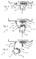
- FIGS. 3 to 5 different operating states of the device 1 according to the invention are shown.
- the representation corresponds to a view from above. Trained as a funnel filling device 3 is partially shown.
- the wolf 5 is connected to the device 1 by means of carrying means 9, which are designed as double hinges.
- the support means 9 have in the illustrated embodiment, a first hinge member 10 and a second hinge member 12.
- the hinge member 10 is pivotally connected on the one hand to the device 1, and on the other hand pivotally connected to the second hinge member 12.
- the second hinge member 12 is further pivotally connected to the housing 6 of the wolf 5.
- the outlet 11 of the wolf 5 is in the selected orientation of the illustration in FIG Fig. 3 aligned parallel to the terminal 8 of the device 1.
- the inlet 13 (not shown) of the wolf 5 is located in the in Fig. 3 shown operating state with the terminal 8 of the device 1 in contact.
- the wolf 5 is further fastened to the device 1 by means of the locking means 7.
- Fig. 4 the wolf 5 is shown in a state spaced from the device 1 state.
- the connection 8 of the device 1 are not in the position shown with each other.
- the locking means 7 are released.
- the support means 9 designed as a double hinge are substantially stretched in comparison to their position Fig. 3 , This extended position of the support means 9 results from the spaced position of the wolf 5 of the device. 1
- the wolf 5 is from the operating condition Fig. 3 in the operating state in Fig. 4 in which a movement has been carried out which guides the wolf 5 substantially along the longitudinal axis 17.
- the longitudinal axis 17 is substantially coaxial with drive means 15, which are designed in the selected embodiment as a drive shaft.
- the stretching of the hinge members 10, 12 and the coaxial movement of the wolf 5 along the longitudinal axis 17 of the drive means 15 in this case mutually condition.
- the wolf 5 is held by the support means 9 in its position spaced from the device. After the wolf 5 has been pulled off the device 1 along the axis 17, it is possible to move the wolf 5 even further.
- FIG. 5 A possible state of motion is below in Fig. 5 displayed.
- the wolf 5 is from the operating condition Fig. 4 in the operating state in Fig. 5 brought by being swung to one side.
- This pivoting movement is supported by the support means 9, in which the first hinge member 10 and the second hinge member 12 of the support means 9 and the wolf 5 perform a planar movement, which corresponds to a triple pendulum in the selected embodiment.
- the first hinge member 10, and the second hinge member 12 and the wolf 5 are adapted to be moved independently of each other.
- the wolf is no longer in a longitudinal axis 17 of the drive means 15 coaxial alignment.
- FIGS. 6 and 7 The operation of a Abdrücktechnikmaschinees 19 according to the present invention is in the FIGS. 6 and 7 illustrated.
- Fig. 6 is the wolf 5, which is connected to a second hinge member 12, shown.
- the housing 6 of the wolf 5 receives the cutting elements 31 and the perforated disc 33. This is especially in Fig. 7 award.
- the cutting elements 31 and the perforated disk 33 shown there are arranged substantially centrally in the housing 6 of the wolf 5 and mounted rotatably about a rotation axis 28.
- the Abdschreibmaschinemaschine 19 extends into the FIGS. 6 and 7 along the axis of rotation 28 at least partially into the interior of the housing 6 of the wolf 5 inside.
- the Abdschreibtechnikmaschine 19 has a guide portion 23 which is formed in the present embodiment as a partially threaded (threaded) rod with a cylindrical cross-section.
- the guide portion 23 is connected by means of fastening means 25 with an arm 29.
- the fastening means 25 are formed in the present embodiment as a screw connection.
- a crank 21 is connected to the arm 29 via fastening means 27.
- the fastening means 27 are designed as a screw connection as well as the fastening means 25 in the present embodiment. It may be advantageous to rotatably attach the crank 21 to the arm 29.
- the Abdschreibmaschinemaschine 1976 19 is in the FIGS. 6 and 7 is introduced with the guide portion 23 on the side of the inlet 13 of the wolf 5 in the housing 6 of the wolf 5. In Fig.
- the guide section 23 of the Abdschreibtechnikmaschinees 19 is disposed substantially outside of the housing 6 of the wolf, and the cutting elements 31 and the perforated disc 33 are arranged substantially in the interior of the housing 6 of the wolf 5.
- the guide portion 23 of the Abdschreibtechnikmaschinees 19 is disposed substantially within the wolf 5, and the cutting element 31 and the perforated disc 33 are disposed substantially outside of the wolf 5 on the side of the outlet 11.
- the expelling of the cutting elements 31 and the perforated disc 33 from the wolf is carried out by inserting the ejection tool 19 with the guide section 23 in the present case on the side of the inlet 13 into the wolf. Subsequently, by applying a force in the direction of the wolf on the Abdschreibtechnikmaschine 19th in particular on the crank 21 and the crank arm 29, that the interior of the wolf 5, in particular the cutting elements 31 and the perforated disc 33, pressed out of the wolf 5 in the direction of the application of force. In the embodiment of FIGS. 6 and 7 This corresponds to the movement in the direction of the side of the outlet 11 of the wolf 5. Depending on the design principle, it is also conceivable that the process of expulsion of the cutting elements 31 and the perforated disc 33 by a rotational movement of the Abdrückmaschinemaschines 19 generated and / or assisted by the crank 21 becomes.
- the rotational movement applied by the crank 21 is converted, by means of the threaded rod cooperating with a thread of the squeezing tool 19, into an axial advancing movement and force by which the cutting elements are forced out through the outlet 11 of the wolf.
- the rotational movement can be applied by means of a motor instead of a crank by means of a drive motor, for example by means of an electric motor or the like.
Landscapes
- Engineering & Computer Science (AREA)
- Life Sciences & Earth Sciences (AREA)
- Food Science & Technology (AREA)
- Wood Science & Technology (AREA)
- Zoology (AREA)
- Crushing And Pulverization Processes (AREA)
- Finish Polishing, Edge Sharpening, And Grinding By Specific Grinding Devices (AREA)
- Food-Manufacturing Devices (AREA)
Claims (15)
- Dispositif (1) de transport et de traitement d'aliments, notamment de viande, ledit dispositif comportant un mécanisme de remplissage (3), un hachoir (5) comportant une entrée (13) et une sortie (11), et des moyens d'entraînement (15) pour entraîner des éléments de coupe (31) disposés dans un boîtier (6) du hachoir (5),
les éléments de coupe (31) étant totalement découplés des moyens d'entraînement (15), et
caractérisé par des moyens de support (9) pour supporter le hachoir (5) pendant le montage, lesquels moyens sont conformés pour supporter le hachoir (5) pendant un déplacement coaxial à un axe (17) des moyens d'entraînement (15),
les moyens de support étant conformés en charnière à éléments multiples de sorte que le hachoir (5) est apte à se déplacer dans une première région sensiblement coaxialement à l'axe (17) des moyens d'entraînement (15), et apte à pivoter dans une seconde région dans une direction latérale,
et les éléments de coupe (31) étant disposés dans le boîtier (6) du hachoir (5) de sorte qu'ils peuvent être retirés du boîtier (6) du hachoir (5) par la sortie (11) au moyen d'une force pouvant être appliquée du côté de l'entrée (13). - Dispositif (1) selon la revendication 1, caractérisé en ce que les éléments de coupe (31) peuvent être extraits du boîtier (6) au moyen d'un outil d'éjection (19) pouvant être inséré à l'intérieur du hachoir (5) du côté de l'entrée (13).
- Dispositif (1) selon la revendication 2, caractérisé en ce qu'un ou plusieurs disques perforés (33) sont disposés dans le hachoir (5) de sorte qu'ils peuvent être retirés du boîtier (6) du hachoir (5) du côté de la sortie (11) conjointement avec les éléments de coupe (31) au moyen de l'outil d'éjection (19).
- Dispositif (1) selon la revendication 2 ou 3, caractérisé en ce que le boîtier (6) du hachoir (5) comporte du côté de l'entrée (13) une ouverture disposée de préférence sensiblement au centre et destinée à recevoir l'outil d'éjection (19).
- Dispositif (1) selon la revendication 1, caractérisé en ce que les moyens de support (9) sont conformés en guide linéaire.
- Dispositif selon l'une des revendications précédentes, caractérisé en ce que le disque perforé disposé au niveau de la sortie (11) du hachoir (5) est fermé en son centre.
- Dispositif (1) selon l'une des revendications précédentes, caractérisé en ce que le hachoir (5) possède des poignées qui sont conformées pour déplacer le hachoir (5) par rapport au dispositif (1).
- Dispositif (1) selon l'une des revendications précédentes, caractérisé par des moyens de blocage (7) qui sont conformés de telle sorte qu'ils relient le boîtier (6) du hachoir (5) de façon amovible à un raccord (8) du dispositif (1).
- Procédé de démontage d'un hachoir (5) d'un dispositif (1) selon l'une des revendications 1 à 8 pour transporter et traiter des aliments, ledit procédé comportant les étapes :de découplage du hachoir (5) de moyens d'entraînement (15), etd'extraction d'éléments de coupe (31) d'un boîtier (6) du hachoir (5) du côté d'une sortie (11) au moyen d'une force qui peut être appliquée du côté de l'entrée (13), caractérisé en ce quele processus de découplage du hachoir est effectué dans les étapes d'extraction axiale du hachoir (5) du dispositif (1), et de pivotement au moins partiel du hachoir (5) sur un côté.
- Procédé selon la revendication 9, caractérisé en ce que l'extraction des éléments de coupe (31) du boîtier (6) du hachoir (5) est effectué par
introduction d'un outil d'éjection (19) à l'intérieur du hachoir (5) du côté de l'entrée (13),
application d'une force de pression sur les éléments de coupe en direction du côté de la sortie (11) du boîtier (6) au moyen de l'outil d'éjection, et
d'extraction des éléments de coupe (31) du hachoir (5). - Procédé selon au moins une des revendications 9 à 10, caractérisé en ce qu'un ou plusieurs disques perforés (33) sont extraits du hachoir conjointement avec les éléments de coupe (31).
- Outil d'éjection (19) destiné à être utilisé avec le dispositif (1) selon l'une des revendications 1 à 8 ou dans un procédé selon l'une des revendications 9 ou 10 ou 11, lequel outil est conformé pour introduire au moins une portion (13) à l'intérieur d'un hachoir (5), et présente une surface de contact qui peut être amenée en contact d'adhérence ou de complémentarité de formes avec des éléments de coupe (31) et/ou un ou plusieurs disques perforés (33) d'un hachoir (5),
caractérisé par une manivelle (21). - Outil d'éjection (19) selon la revendication 12, caractérisé en ce qu'il comporte des moyens de raccordement pour la fixation au boîtier (6) du hachoir.
- Outil d'éjection selon l'une des revendications précédentes, caractérisé en ce que la portion introduite (13) est conformée de façon à retirer les éléments de coupe (31) du boîtier (6) du hachoir (5) par la sortie (11) au moyen d'une force qui peut être appliquée sur les éléments de coupe (31) du côté de l'entrée (13).
- Outil d'éjection selon l'une des revendications précédentes, caractérisé en ce qu'un mouvement de rotation, communiquée avantageusement par la manivelle ou un moteur, peut être converti, au moyen d'une barre filetée qui coopère avec un filetage de l'outil d'éjection (19), en un mouvement d'avancement axial et une force par lesquels les éléments de coupe (31) peuvent être extraits par la sortie (11) du hachoir (5).
Applications Claiming Priority (1)
| Application Number | Priority Date | Filing Date | Title |
|---|---|---|---|
| DE102008013393A DE102008013393B4 (de) | 2008-03-10 | 2008-03-10 | Vorrichtung zum Fördern und Bearbeiten von Lebensmitteln |
Publications (2)
| Publication Number | Publication Date |
|---|---|
| EP2100513A1 EP2100513A1 (fr) | 2009-09-16 |
| EP2100513B1 true EP2100513B1 (fr) | 2012-05-16 |
Family
ID=40626919
Family Applications (1)
| Application Number | Title | Priority Date | Filing Date |
|---|---|---|---|
| EP09154646A Active EP2100513B1 (fr) | 2008-03-10 | 2009-03-09 | Dispositif de transport et de traitement d'aliments |
Country Status (4)
| Country | Link |
|---|---|
| US (1) | US8100355B2 (fr) |
| EP (1) | EP2100513B1 (fr) |
| DE (1) | DE102008013393B4 (fr) |
| ES (1) | ES2386100T3 (fr) |
Families Citing this family (5)
| Publication number | Priority date | Publication date | Assignee | Title |
|---|---|---|---|---|
| DE102004027024A1 (de) * | 2004-03-17 | 2005-10-06 | Cfs Germany Gmbh | Fleischverarbeitungsmaschine mit Fettanalysevorrichtung |
| FR2963876B1 (fr) * | 2010-08-23 | 2013-09-20 | Guelt | Hachoir equipe d'un systeme pour le montage/demontage de sa vis d'alimentation |
| DE202011005356U1 (de) | 2011-04-18 | 2011-06-09 | VEMAG Maschinenbau GmbH, 27283 | Lochscheibe zum Verarbeiten von Lebensmitteln |
| US10363563B2 (en) * | 2015-02-09 | 2019-07-30 | Thomas Precision Machining, Inc. | Grinder plate and tool for removal and installation thereof |
| DE202019106178U1 (de) | 2019-11-06 | 2021-02-10 | Vemag Maschinenbau Gmbh | Darmhaltevorrichtung für eine Vorrichtung zum Füllen schlauchförmiger Hüllen |
Family Cites Families (9)
| Publication number | Priority date | Publication date | Assignee | Title |
|---|---|---|---|---|
| US3125144A (en) * | 1964-03-17 | Locking means for meat chopper | ||
| US2539448A (en) * | 1948-06-26 | 1951-01-30 | Globe Slicing Machine Co Inc | Commodity chopper casing |
| DE811793C (de) | 1949-03-24 | 1951-08-23 | Emil Elstner | Geraet zum Reinigen von Fleischwolf-Lochscheiben |
| US3414925A (en) | 1966-06-24 | 1968-12-10 | Andrew H. Stavros | Cleaner for meat grinder heads |
| DE2044228C3 (de) * | 1970-09-07 | 1974-02-07 | Kraemer & Grebe Kg, Maschinen Und Modellfabrik, 3562 Wallau | Vorrichtung zum Zerkleinern und zur Wärmebehandlung von Fleisch |
| DD108214A1 (fr) * | 1973-12-18 | 1974-09-12 | ||
| DE19942311C2 (de) | 1999-09-04 | 2001-06-28 | Fehb Gmbh | Spann- und Auszugssystem |
| DE202004007788U1 (de) | 2004-05-12 | 2005-09-22 | Tipper Tie Technopack Gmbh | Aufhängung für ein Füllrohr zum Abfüllen von Würsten |
| AT503389B1 (de) * | 2006-03-24 | 2008-03-15 | Laska Maschf Gmbh | Fleischwolf |
-
2008
- 2008-03-10 DE DE102008013393A patent/DE102008013393B4/de not_active Expired - Fee Related
-
2009
- 2009-03-09 EP EP09154646A patent/EP2100513B1/fr active Active
- 2009-03-09 US US12/400,066 patent/US8100355B2/en active Active
- 2009-03-09 ES ES09154646T patent/ES2386100T3/es active Active
Also Published As
| Publication number | Publication date |
|---|---|
| US20090224085A1 (en) | 2009-09-10 |
| US8100355B2 (en) | 2012-01-24 |
| ES2386100T3 (es) | 2012-08-09 |
| DE102008013393B4 (de) | 2011-07-28 |
| DE102008013393A1 (de) | 2009-09-24 |
| EP2100513A1 (fr) | 2009-09-16 |
Similar Documents
| Publication | Publication Date | Title |
|---|---|---|
| EP2938799B9 (fr) | Dispositif broyeur de denrées alimentaires | |
| DE69109804T2 (de) | Gerät zum Trennen des Kernes, der Schale und des Fleisches einer Frucht, insbesondere einer Ananas. | |
| EP2100513B1 (fr) | Dispositif de transport et de traitement d'aliments | |
| WO2020200759A1 (fr) | Broyeur à couteaux de laboratoire pour le broyage par découpage d'échantillons | |
| AT392198B (de) | Vorrichtung zur behandlung von fleisch | |
| DE20301354U1 (de) | Zerkleinerungsvorrichtung | |
| DE102018112902B4 (de) | Abstreifelement zum Abstreifen von außen an einer Hohltrommel einer Vorrichtung zum Trennen von miteinander vermischten Stoffen unterschiedlicher Fließfähigkeit anliegenden Stoffresten sowie Vorrichtung mit einem solchen Abstreifelement | |
| DE3344284A1 (de) | Vorrichtung zur behandlung von fleisch oder schinken, insbesondere von kochpoekelwaren | |
| AT523406B1 (de) | Zerkleinerungsmaschine | |
| EP2198717A2 (fr) | Dispositif de remplissage ou de traitement de masses pâteuses, notamment chaire à saucisse | |
| DE2901909C2 (de) | Vorrichtung zum Abtrennen von Restfleisch von Knochen und Verfahren zum Betrieb dieser Vorrichtung | |
| EP1447006B1 (fr) | Dispositif de dosage pour produits alimentaires | |
| EP3085447B1 (fr) | Unité de fixation d'un broyeur à billes a agitateur, broyeur à billes à agitateur et procédé pour desserrer une unité de fixation | |
| DE2107134C3 (de) | Schneidmaschine | |
| EP2229110B1 (fr) | Dispositif rapporté pour dispositif chirurgical et dispositif chirurgical correspondant pour percer un os | |
| DE4229338A1 (de) | Füllkammer für eine Druckgießmaschine | |
| EP3390929A1 (fr) | Dispositif de broyage d'au moins un morceau de produit congelé | |
| EP1145654B1 (fr) | Eplucheuse | |
| WO2022258171A1 (fr) | Appareil de transformation pour des denrées alimentaires | |
| WO2002076220A1 (fr) | Procede pour fileter des poissons evisceres, a cavite abdominale ouverte, et dispositif pour mettre en oeuvre ledit procede | |
| DE102022122711B3 (de) | Zerkleinerungsmaschine mit einem mehrteiligen Gehäuse | |
| EP2620262B1 (fr) | Agencement d'embrayage pour un disjoncteur | |
| DE19706425C1 (de) | Zerlegbare Laborschneidmühle | |
| AT225058B (de) | Maschine zum Abziehen der Schwarte oder Haut bei Speck oder Fleisch | |
| AT254734B (de) | Zerkleinerungsvorrichtung für Nahrungsmittel und Tierfuttermittel |
Legal Events
| Date | Code | Title | Description |
|---|---|---|---|
| PUAI | Public reference made under article 153(3) epc to a published international application that has entered the european phase |
Free format text: ORIGINAL CODE: 0009012 |
|
| AK | Designated contracting states |
Kind code of ref document: A1 Designated state(s): AT BE BG CH CY CZ DE DK EE ES FI FR GB GR HR HU IE IS IT LI LT LU LV MC MK MT NL NO PL PT RO SE SI SK TR |
|
| AX | Request for extension of the european patent |
Extension state: AL BA RS |
|
| 17P | Request for examination filed |
Effective date: 20100316 |
|
| AKX | Designation fees paid |
Designated state(s): AT BE BG CH CY CZ DE DK EE ES FI FR GB GR HR HU IE IS IT LI LT LU LV MC MK MT NL NO PL PT RO SE SI SK TR |
|
| REG | Reference to a national code |
Ref country code: DE Ref legal event code: R079 Ref document number: 502009003534 Country of ref document: DE Free format text: PREVIOUS MAIN CLASS: A22C0011020000 Ipc: B02C0018300000 |
|
| GRAP | Despatch of communication of intention to grant a patent |
Free format text: ORIGINAL CODE: EPIDOSNIGR1 |
|
| RIC1 | Information provided on ipc code assigned before grant |
Ipc: B02C 18/38 20060101ALI20110927BHEP Ipc: B02C 18/30 20060101AFI20110927BHEP |
|
| GRAS | Grant fee paid |
Free format text: ORIGINAL CODE: EPIDOSNIGR3 |
|
| GRAA | (expected) grant |
Free format text: ORIGINAL CODE: 0009210 |
|
| AK | Designated contracting states |
Kind code of ref document: B1 Designated state(s): AT BE BG CH CY CZ DE DK EE ES FI FR GB GR HR HU IE IS IT LI LT LU LV MC MK MT NL NO PL PT RO SE SI SK TR |
|
| REG | Reference to a national code |
Ref country code: GB Ref legal event code: FG4D Free format text: NOT ENGLISH |
|
| REG | Reference to a national code |
Ref country code: CH Ref legal event code: EP |
|
| REG | Reference to a national code |
Ref country code: AT Ref legal event code: REF Ref document number: 557782 Country of ref document: AT Kind code of ref document: T Effective date: 20120615 |
|
| REG | Reference to a national code |
Ref country code: IE Ref legal event code: FG4D Free format text: LANGUAGE OF EP DOCUMENT: GERMAN |
|
| REG | Reference to a national code |
Ref country code: DE Ref legal event code: R096 Ref document number: 502009003534 Country of ref document: DE Effective date: 20120712 |
|
| REG | Reference to a national code |
Ref country code: ES Ref legal event code: FG2A Ref document number: 2386100 Country of ref document: ES Kind code of ref document: T3 Effective date: 20120809 |
|
| REG | Reference to a national code |
Ref country code: NL Ref legal event code: T3 |
|
| REG | Reference to a national code |
Ref country code: LT Ref legal event code: MG4D Effective date: 20120516 |
|
| PG25 | Lapsed in a contracting state [announced via postgrant information from national office to epo] |
Ref country code: CY Free format text: LAPSE BECAUSE OF FAILURE TO SUBMIT A TRANSLATION OF THE DESCRIPTION OR TO PAY THE FEE WITHIN THE PRESCRIBED TIME-LIMIT Effective date: 20120516 Ref country code: PL Free format text: LAPSE BECAUSE OF FAILURE TO SUBMIT A TRANSLATION OF THE DESCRIPTION OR TO PAY THE FEE WITHIN THE PRESCRIBED TIME-LIMIT Effective date: 20120516 Ref country code: FI Free format text: LAPSE BECAUSE OF FAILURE TO SUBMIT A TRANSLATION OF THE DESCRIPTION OR TO PAY THE FEE WITHIN THE PRESCRIBED TIME-LIMIT Effective date: 20120516 Ref country code: NO Free format text: LAPSE BECAUSE OF FAILURE TO SUBMIT A TRANSLATION OF THE DESCRIPTION OR TO PAY THE FEE WITHIN THE PRESCRIBED TIME-LIMIT Effective date: 20120816 Ref country code: IS Free format text: LAPSE BECAUSE OF FAILURE TO SUBMIT A TRANSLATION OF THE DESCRIPTION OR TO PAY THE FEE WITHIN THE PRESCRIBED TIME-LIMIT Effective date: 20120916 Ref country code: SE Free format text: LAPSE BECAUSE OF FAILURE TO SUBMIT A TRANSLATION OF THE DESCRIPTION OR TO PAY THE FEE WITHIN THE PRESCRIBED TIME-LIMIT Effective date: 20120516 Ref country code: LT Free format text: LAPSE BECAUSE OF FAILURE TO SUBMIT A TRANSLATION OF THE DESCRIPTION OR TO PAY THE FEE WITHIN THE PRESCRIBED TIME-LIMIT Effective date: 20120516 |
|
| PG25 | Lapsed in a contracting state [announced via postgrant information from national office to epo] |
Ref country code: PT Free format text: LAPSE BECAUSE OF FAILURE TO SUBMIT A TRANSLATION OF THE DESCRIPTION OR TO PAY THE FEE WITHIN THE PRESCRIBED TIME-LIMIT Effective date: 20120917 Ref country code: HR Free format text: LAPSE BECAUSE OF FAILURE TO SUBMIT A TRANSLATION OF THE DESCRIPTION OR TO PAY THE FEE WITHIN THE PRESCRIBED TIME-LIMIT Effective date: 20120516 Ref country code: GR Free format text: LAPSE BECAUSE OF FAILURE TO SUBMIT A TRANSLATION OF THE DESCRIPTION OR TO PAY THE FEE WITHIN THE PRESCRIBED TIME-LIMIT Effective date: 20120817 Ref country code: LV Free format text: LAPSE BECAUSE OF FAILURE TO SUBMIT A TRANSLATION OF THE DESCRIPTION OR TO PAY THE FEE WITHIN THE PRESCRIBED TIME-LIMIT Effective date: 20120516 Ref country code: SI Free format text: LAPSE BECAUSE OF FAILURE TO SUBMIT A TRANSLATION OF THE DESCRIPTION OR TO PAY THE FEE WITHIN THE PRESCRIBED TIME-LIMIT Effective date: 20120516 |
|
| PG25 | Lapsed in a contracting state [announced via postgrant information from national office to epo] |
Ref country code: RO Free format text: LAPSE BECAUSE OF FAILURE TO SUBMIT A TRANSLATION OF THE DESCRIPTION OR TO PAY THE FEE WITHIN THE PRESCRIBED TIME-LIMIT Effective date: 20120516 Ref country code: SK Free format text: LAPSE BECAUSE OF FAILURE TO SUBMIT A TRANSLATION OF THE DESCRIPTION OR TO PAY THE FEE WITHIN THE PRESCRIBED TIME-LIMIT Effective date: 20120516 Ref country code: CZ Free format text: LAPSE BECAUSE OF FAILURE TO SUBMIT A TRANSLATION OF THE DESCRIPTION OR TO PAY THE FEE WITHIN THE PRESCRIBED TIME-LIMIT Effective date: 20120516 Ref country code: DK Free format text: LAPSE BECAUSE OF FAILURE TO SUBMIT A TRANSLATION OF THE DESCRIPTION OR TO PAY THE FEE WITHIN THE PRESCRIBED TIME-LIMIT Effective date: 20120516 Ref country code: EE Free format text: LAPSE BECAUSE OF FAILURE TO SUBMIT A TRANSLATION OF THE DESCRIPTION OR TO PAY THE FEE WITHIN THE PRESCRIBED TIME-LIMIT Effective date: 20120516 |
|
| PG25 | Lapsed in a contracting state [announced via postgrant information from national office to epo] |
Ref country code: IT Free format text: LAPSE BECAUSE OF FAILURE TO SUBMIT A TRANSLATION OF THE DESCRIPTION OR TO PAY THE FEE WITHIN THE PRESCRIBED TIME-LIMIT Effective date: 20120516 |
|
| PLBE | No opposition filed within time limit |
Free format text: ORIGINAL CODE: 0009261 |
|
| STAA | Information on the status of an ep patent application or granted ep patent |
Free format text: STATUS: NO OPPOSITION FILED WITHIN TIME LIMIT |
|
| 26N | No opposition filed |
Effective date: 20130219 |
|
| REG | Reference to a national code |
Ref country code: DE Ref legal event code: R097 Ref document number: 502009003534 Country of ref document: DE Effective date: 20130219 |
|
| PG25 | Lapsed in a contracting state [announced via postgrant information from national office to epo] |
Ref country code: BG Free format text: LAPSE BECAUSE OF FAILURE TO SUBMIT A TRANSLATION OF THE DESCRIPTION OR TO PAY THE FEE WITHIN THE PRESCRIBED TIME-LIMIT Effective date: 20120816 |
|
| BERE | Be: lapsed |
Owner name: VEMAG MASCHINENBAU G.M.B.H. Effective date: 20130331 |
|
| PG25 | Lapsed in a contracting state [announced via postgrant information from national office to epo] |
Ref country code: MC Free format text: LAPSE BECAUSE OF NON-PAYMENT OF DUE FEES Effective date: 20130331 |
|
| REG | Reference to a national code |
Ref country code: CH Ref legal event code: PL |
|
| REG | Reference to a national code |
Ref country code: IE Ref legal event code: MM4A |
|
| PG25 | Lapsed in a contracting state [announced via postgrant information from national office to epo] |
Ref country code: CH Free format text: LAPSE BECAUSE OF NON-PAYMENT OF DUE FEES Effective date: 20130331 Ref country code: LI Free format text: LAPSE BECAUSE OF NON-PAYMENT OF DUE FEES Effective date: 20130331 Ref country code: IE Free format text: LAPSE BECAUSE OF NON-PAYMENT OF DUE FEES Effective date: 20130309 Ref country code: BE Free format text: LAPSE BECAUSE OF NON-PAYMENT OF DUE FEES Effective date: 20130331 |
|
| PG25 | Lapsed in a contracting state [announced via postgrant information from national office to epo] |
Ref country code: MT Free format text: LAPSE BECAUSE OF FAILURE TO SUBMIT A TRANSLATION OF THE DESCRIPTION OR TO PAY THE FEE WITHIN THE PRESCRIBED TIME-LIMIT Effective date: 20120516 |
|
| PG25 | Lapsed in a contracting state [announced via postgrant information from national office to epo] |
Ref country code: TR Free format text: LAPSE BECAUSE OF FAILURE TO SUBMIT A TRANSLATION OF THE DESCRIPTION OR TO PAY THE FEE WITHIN THE PRESCRIBED TIME-LIMIT Effective date: 20120516 |
|
| PG25 | Lapsed in a contracting state [announced via postgrant information from national office to epo] |
Ref country code: MK Free format text: LAPSE BECAUSE OF FAILURE TO SUBMIT A TRANSLATION OF THE DESCRIPTION OR TO PAY THE FEE WITHIN THE PRESCRIBED TIME-LIMIT Effective date: 20120516 Ref country code: HU Free format text: LAPSE BECAUSE OF FAILURE TO SUBMIT A TRANSLATION OF THE DESCRIPTION OR TO PAY THE FEE WITHIN THE PRESCRIBED TIME-LIMIT; INVALID AB INITIO Effective date: 20090309 Ref country code: LU Free format text: LAPSE BECAUSE OF NON-PAYMENT OF DUE FEES Effective date: 20130309 |
|
| REG | Reference to a national code |
Ref country code: FR Ref legal event code: PLFP Year of fee payment: 8 |
|
| REG | Reference to a national code |
Ref country code: FR Ref legal event code: PLFP Year of fee payment: 9 |
|
| REG | Reference to a national code |
Ref country code: FR Ref legal event code: PLFP Year of fee payment: 10 |
|
| PGFP | Annual fee paid to national office [announced via postgrant information from national office to epo] |
Ref country code: NL Payment date: 20240320 Year of fee payment: 16 |
|
| PGFP | Annual fee paid to national office [announced via postgrant information from national office to epo] |
Ref country code: GB Payment date: 20240322 Year of fee payment: 16 |
|
| PGFP | Annual fee paid to national office [announced via postgrant information from national office to epo] |
Ref country code: FR Payment date: 20240319 Year of fee payment: 16 |
|
| PGFP | Annual fee paid to national office [announced via postgrant information from national office to epo] |
Ref country code: AT Payment date: 20250319 Year of fee payment: 17 |
|
| PGFP | Annual fee paid to national office [announced via postgrant information from national office to epo] |
Ref country code: DE Payment date: 20250409 Year of fee payment: 17 |
|
| PGFP | Annual fee paid to national office [announced via postgrant information from national office to epo] |
Ref country code: ES Payment date: 20250416 Year of fee payment: 17 |
|
| REG | Reference to a national code |
Ref country code: NL Ref legal event code: MM Effective date: 20250401 |
|
| GBPC | Gb: european patent ceased through non-payment of renewal fee |
Effective date: 20250309 |
|
| PG25 | Lapsed in a contracting state [announced via postgrant information from national office to epo] |
Ref country code: NL Free format text: LAPSE BECAUSE OF NON-PAYMENT OF DUE FEES Effective date: 20250401 |
|
| PG25 | Lapsed in a contracting state [announced via postgrant information from national office to epo] |
Ref country code: GB Free format text: LAPSE BECAUSE OF NON-PAYMENT OF DUE FEES Effective date: 20250309 |
|
| PG25 | Lapsed in a contracting state [announced via postgrant information from national office to epo] |
Ref country code: FR Free format text: LAPSE BECAUSE OF NON-PAYMENT OF DUE FEES Effective date: 20250331 |