EP2100544A1 - Druckkochgerät zum Zubereiten von Nahrungsmitteln, das ein Deckelmodul umfasst - Google Patents
Druckkochgerät zum Zubereiten von Nahrungsmitteln, das ein Deckelmodul umfasst Download PDFInfo
- Publication number
- EP2100544A1 EP2100544A1 EP09006219A EP09006219A EP2100544A1 EP 2100544 A1 EP2100544 A1 EP 2100544A1 EP 09006219 A EP09006219 A EP 09006219A EP 09006219 A EP09006219 A EP 09006219A EP 2100544 A1 EP2100544 A1 EP 2100544A1
- Authority
- EP
- European Patent Office
- Prior art keywords
- module
- pressure
- lid
- cover
- cooking
- Prior art date
- Legal status (The legal status is an assumption and is not a legal conclusion. Google has not performed a legal analysis and makes no representation as to the accuracy of the status listed.)
- Granted
Links
- 238000010411 cooking Methods 0.000 title claims abstract description 66
- 235000013305 food Nutrition 0.000 title claims description 11
- 238000004891 communication Methods 0.000 claims abstract description 25
- 230000000694 effects Effects 0.000 claims abstract description 8
- 230000002159 abnormal effect Effects 0.000 claims abstract description 3
- 230000001105 regulatory effect Effects 0.000 claims description 12
- 230000006837 decompression Effects 0.000 claims description 4
- 230000000750 progressive effect Effects 0.000 claims description 4
- 230000005540 biological transmission Effects 0.000 description 17
- 238000006073 displacement reaction Methods 0.000 description 8
- 230000009471 action Effects 0.000 description 7
- 230000006835 compression Effects 0.000 description 7
- 238000007906 compression Methods 0.000 description 7
- 238000010926 purge Methods 0.000 description 7
- 238000013519 translation Methods 0.000 description 6
- 230000000295 complement effect Effects 0.000 description 5
- 230000002441 reversible effect Effects 0.000 description 5
- 230000001276 controlling effect Effects 0.000 description 4
- 230000004069 differentiation Effects 0.000 description 3
- 238000005406 washing Methods 0.000 description 3
- 230000008901 benefit Effects 0.000 description 2
- 238000013461 design Methods 0.000 description 2
- 238000004519 manufacturing process Methods 0.000 description 2
- 239000002184 metal Substances 0.000 description 2
- 229910052751 metal Inorganic materials 0.000 description 2
- 238000000034 method Methods 0.000 description 2
- 230000036961 partial effect Effects 0.000 description 2
- 230000002093 peripheral effect Effects 0.000 description 2
- BASFCYQUMIYNBI-UHFFFAOYSA-N platinum Chemical compound [Pt] BASFCYQUMIYNBI-UHFFFAOYSA-N 0.000 description 2
- 230000008569 process Effects 0.000 description 2
- 238000012545 processing Methods 0.000 description 2
- 230000009467 reduction Effects 0.000 description 2
- 238000007789 sealing Methods 0.000 description 2
- 238000009825 accumulation Methods 0.000 description 1
- 238000013459 approach Methods 0.000 description 1
- 230000000712 assembly Effects 0.000 description 1
- 238000000429 assembly Methods 0.000 description 1
- 238000004140 cleaning Methods 0.000 description 1
- 238000010586 diagram Methods 0.000 description 1
- 238000005553 drilling Methods 0.000 description 1
- 239000010794 food waste Substances 0.000 description 1
- 230000010354 integration Effects 0.000 description 1
- 230000003993 interaction Effects 0.000 description 1
- 230000002427 irreversible effect Effects 0.000 description 1
- 230000000670 limiting effect Effects 0.000 description 1
- 230000007774 longterm Effects 0.000 description 1
- 238000002844 melting Methods 0.000 description 1
- 230000008018 melting Effects 0.000 description 1
- 239000007769 metal material Substances 0.000 description 1
- 239000000203 mixture Substances 0.000 description 1
- 238000003032 molecular docking Methods 0.000 description 1
- 235000016709 nutrition Nutrition 0.000 description 1
- 229910052697 platinum Inorganic materials 0.000 description 1
- 238000003825 pressing Methods 0.000 description 1
- 230000001681 protective effect Effects 0.000 description 1
- 230000002829 reductive effect Effects 0.000 description 1
- 230000011664 signaling Effects 0.000 description 1
- 229910001220 stainless steel Inorganic materials 0.000 description 1
- 239000010935 stainless steel Substances 0.000 description 1
- 230000001960 triggered effect Effects 0.000 description 1
- 229940088594 vitamin Drugs 0.000 description 1
- 229930003231 vitamin Natural products 0.000 description 1
- 235000013343 vitamin Nutrition 0.000 description 1
- 239000011782 vitamin Substances 0.000 description 1
Images

Classifications
-
- A—HUMAN NECESSITIES
- A47—FURNITURE; DOMESTIC ARTICLES OR APPLIANCES; COFFEE MILLS; SPICE MILLS; SUCTION CLEANERS IN GENERAL
- A47J—KITCHEN EQUIPMENT; COFFEE MILLS; SPICE MILLS; APPARATUS FOR MAKING BEVERAGES
- A47J27/00—Cooking-vessels
- A47J27/08—Pressure-cookers; Lids or locking devices specially adapted therefor
- A47J27/09—Safety devices
-
- A—HUMAN NECESSITIES
- A47—FURNITURE; DOMESTIC ARTICLES OR APPLIANCES; COFFEE MILLS; SPICE MILLS; SUCTION CLEANERS IN GENERAL
- A47J—KITCHEN EQUIPMENT; COFFEE MILLS; SPICE MILLS; APPARATUS FOR MAKING BEVERAGES
- A47J27/00—Cooking-vessels
- A47J27/08—Pressure-cookers; Lids or locking devices specially adapted therefor
- A47J27/0804—Locking devices
- A47J27/0813—Locking devices using a clamping ring or clamping segments
-
- Y—GENERAL TAGGING OF NEW TECHNOLOGICAL DEVELOPMENTS; GENERAL TAGGING OF CROSS-SECTIONAL TECHNOLOGIES SPANNING OVER SEVERAL SECTIONS OF THE IPC; TECHNICAL SUBJECTS COVERED BY FORMER USPC CROSS-REFERENCE ART COLLECTIONS [XRACs] AND DIGESTS
- Y10—TECHNICAL SUBJECTS COVERED BY FORMER USPC
- Y10S—TECHNICAL SUBJECTS COVERED BY FORMER USPC CROSS-REFERENCE ART COLLECTIONS [XRACs] AND DIGESTS
- Y10S220/00—Receptacles
- Y10S220/912—Cookware, i.e. pots and pans
Definitions
- the present invention relates to the general technical field of domestic cooking appliances under pressure comprising a tank and a lid intended to be locked on the tank to form a sealed cooking chamber, said apparatus being intended to provide steam cooking under pressure. food contained in the tank.
- the present invention also relates to a module for household cooking appliance for use and mounted on a pressure cooker lid.
- control means and at least the locking valve are mounted on the lid of these known pressure cookers.
- the lid of these known devices therefore incorporates a series of devices providing various functions for the user, including at least the opening / closing control functions or safety opening and closing in case of poor closure.
- the cover of these known devices can also integrate other devices providing other functions for the user, such as control functions, safety or control.
- the distinctive signs of belonging to a commercial range of known pressure cookers described above are generally located on the parts performing the functions for the user mentioned above. Indeed, these parts lend themselves more easily than the cover itself, and at a lower cost, work of form, color, or surface appearance, which clearly identify a product visually. For reasons of industrial standardization, it is therefore interesting, for a given pressure cooker size, to produce a single model of lid and tank, the differentiation of the products being done by the contribution of external parts, for example those ensuring the functions for the user.
- control, regulation, safety or control elements on the lid of a pressure cooker is generally complex from an industrial point of view, in particular because of the very different nature of said elements and the lid, the former generally consist of mostly plastic assemblies under the micromechanics, while the cover is derived from a metallurgical metal processing process. It is therefore generally necessary to start providing the cover with the elements providing the functions for the user at a relatively early stage of the production process.
- the objects assigned to the invention therefore aim to remedy the various drawbacks enumerated above, and to propose a new pressurized cooking apparatus with jaw closure, the cleaning of which is facilitated and whose design allows a great flexibility of product differentiation. as well as easy editing.
- Another object of the invention is to propose a new pressurized cooking apparatus with jaw closure, the design of which is simplified.
- Another object of the invention is to provide a new pressurized cooking apparatus with a particularly robust and compact jaw closure.
- Another object of the invention is to provide a new pressurized cooking apparatus with jaw closure, the movement of the jaws is facilitated.
- Another object of the invention is to propose a new pressurized cooking appliance with jaw closure, the level of safety and reliability of which is improved.
- the objects assigned to the invention are also achieved by means of a module for a food cooking appliance intended to be used and mounted on a lid of a pressure cooking appliance according to the invention.
- the cooking apparatus according to the invention is intended to ensure the cooking of different foods, under pressure, in a domestic context.
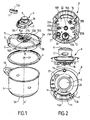
- the cooking apparatus comprises a vessel 1 of substantially cylindrical shape of axis of symmetry (and revolution) X-X ', on which a cover 2 is intended to be sealed.
- the adjective " axial " will refer to the direction of this axis of symmetry, which is similar to the vertical direction when the pressure cooker is in normal operation.
- the tank 1 is conventionally made from a metallic material such as stainless steel and provided with a heat-conducting bottom 1A integral with the tank 1 for example by hot stamping.
- the tank 1 also comprises gripping members such as handles 1B fixed to the walls of the tank 1.
- the lid 2 is of discoidal general shape, and is locked on the tank 1 by means of at least one jaw 3 mounted movably between a locking position, in which the lid is secured to the tank, and an unlocking position, in which the lid can be removed from the tank.
- the jaw 3 is conventionally in the form of segments of U-shaped profiles adapted to the shape of the container, and in the case shown in the figures, in the form of arcs of circles, optionally indented, of determined length.
- the jaw 3 comprises a lower rim 3B and an upper rim 3A for gripping respectively the peripheral rim of the vessel 1 and the peripheral rim of the lid 2.
- the seal is thus obtained by locking the lid 2 on the tank 1, the lid 2 being provided with a sealing means constituted for example by an annular seal 4 lid.
- the pressurized cooking appliance comprises at least one module 6 intended to be attached and removably attached to the lid 2.
- module denotes a unitary and unitary component, of the platinum type, which is capable of being intimately combined with the lid 2, so as to form with the latter a unitary unit with possibly one-piece character.
- a module here designates a substantially monoblock subset, forming an identifiable unit, which can be juxtapose or combine with other components of the system that forms the pressure cooker.
- the removability of the module corresponds for the latter to an ability to be mounted and dismounted easily and at will on the cover, through or not a suitable tool, and preferably manually.
- the module 6 comprises at least one control device 7, 8, 17 of the locking / unlocking of the lid 2 relative to the vessel 1.
- the cover 2 on the one hand and the module 6 on the other hand are each provided with mechanical interfacing means 10A, 10B, 20A, 20B, which cooperate when the module 6 is attached and fixed to the cover 2, so that the lock command or unlocking prescribed by the user is reflected, via the drive means 5, on the jaw (s) 3, causing its (their) opening (placing in the unlocked position) or its (their) closing (setting in the locking position), according to the nature of the order prescribed by the user.
- the module 6 of the cooking appliance according to the invention comprises a timer 11.
- the timer 11 will be a timer removably mounted on the module 6, so that the user can extract from the pressure cooker to keep it on or near it.
- a timer is any device provided with means for counting time, by any means whatsoever (mechanical, electronic or otherwise).
- the timer 11 is provided with an LCD 11A reading information (including time) and 11B buttons for making different settings, for example, time.
- the module 6 of the pressure cooker incorporates a pressure regulating valve 12 equipped with a seal 12A.
- incorporating is meant that the pressure regulating valve 12 is an integral part of the module 6.
- the valve 12 is arranged within the module 6, so as to be in sealed communication with a regulating opening 12B, formed in the cover 2, when the module 6 is attached and fixed to said cover 2.
- the valve 12 is sensitive to the pressure prevailing in the cooking chamber and is movably mounted between two stable stop positions, the first in which it closes the communication of the enclosure towards the outside of the device as long as the internal pressure is lower than a predetermined pressure P 1 , the second in which it puts the inside of the enclosure into communication with the outside of the device, by a steam outlet 13, as soon as the internal pressure substantially reaches the predetermined pressure P 1 .
- the pressure P 1 will be chosen as the normal cooking pressure of the pressure cooker.
- valve devices are well known to those skilled in the art, and are intended to achieve a regulation of the cooking pressure which must be maintained below a predetermined threshold P 1 , value from which the valve 12 provides a vapor leak regulating the internal pressure of the pressure cooker.
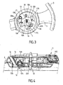
- valve 12 may advantageously be a weight or compression spring valve mounted movable in a well, between a stable stop position illustrated in FIG. figure 4 in which is rests under its own weight on a seat formed around the regulating opening 12B, by drilling into the lid 2.
- the valve 12 may also occupy a high abutment position (not shown in the figures) under the effect of the internal operating pressure of the pressure cooker, when the latter reaches or exceeds the predetermined operating value P 1 . In this position, the valve 12 rises and disengages the regulating opening 12B, through which the vapor can escape outwards, through the opening 12B through a steam outlet 13, located immediately or at close vicinity of said regulating opening 12, and in sealed communication therewith, through a seal 13A.
- valve 12 may be provided with a calibration system, allowing the user to select a predetermined cooking pressure P 1 from a choice of two or more levels of temperature. pressure, via a pressure selection member 14 incorporated in the module 6, depending on the type of food present in the pressure cooker.
- the module 6 incorporates one or more sensor (s) intended (s) to provide information concerning the physical conditions prevailing in the cooking chamber.
- This (s) sensor (s) can (can) thus consist of a pressure sensor and / or a temperature sensor.
- the module 6 of the cooking appliance according to the invention incorporates a temperature sensor 15 disposed in the vicinity of the steam outlet 13, to enable the increase in temperature resulting from the passage of the steam to be sensed through the steam outlet 13.
- the temperature sensor 15 will advantageously be functionally connected to the timer 11, so as to ensure the triggering of the latter as soon as the temperature rise is sensed.
- the sensor 15 used may advantageously be a CTN type sensor operatively connected by a suitable connector 15A, and via a processing electronics, to the timer 11.
- the module 6 is provided with a housing 11C for receiving the timer 11.
- the housing 11C is provided with at least one electrical connection pad operatively connected to the temperature sensor.
- the at least one connection pad is a male connector 11 D.
- the temperature sensor 15 may be connected to an element other than a timer, and for example to a safety device signaling, for example, audibly, the reaching of a predetermined critical pressure or of a predetermined temperature critical.
- the module 6 of the cooking appliance incorporates an overpressure safety valve 16, which is arranged within the module 6 so as to be in sealed communication when the module 6 is attached and fixed to the lid 2, via a seal 16A with a decompression opening 16B formed in the cover 2.
- the overpressure safety valve 16 is sensitive to the pressure prevailing in the cooking chamber and is movably mounted between two stable abutment positions, the first one in which the said safety valve 16 closes the communication of the cooking chamber with the outside as long as the internal pressure is below a predetermined pressure P 2 , the second in which it communicates the inside of the chamber with the outside, as soon as the internal pressure substantially reaches the predetermined pressure P 2 .
- the overpressure safety valve 16 may be a weight, spring or valve by ejection of parts or melting.
- the module 6 incorporates the drive means 5 of the at least one jaw 3.
- the module 6 incorporates the at least one jaw 3, the drive means 5 being integral with the cover 2, with a mechanical interfacing means for performing a drive connection between the drive means 5 and the at least one jaw 3 integral with the module 6.
- the module 6 incorporates both the drive means 5 and the at least one jaw 3, the cover 2 thus being reduced to a very simple piece, possibly provided with means for guiding the drive means 5. .
- the at least one jaw 3 is mounted mobile in translation by at least one respective driving arm 5, between the locking position and the unlocking position.
- the at least one jaw 3 is mounted to move in translation in a substantially radial direction.
- the locking / unlocking control device 7, 8, 17 may be of any type known to those skilled in the art, and for example similar to one of those described in the patent application.
- WO-96/01069 the same applicant, that is to say comprising a control member 7 of the displacement of the jaws 3 mounted radially movable and engaging the drive means 5 so as to control its radial displacement.
- the locking / unlocking control device comprises a main control member 7 mounted to move in translation and an intermediate transmission member 17 positioned in free rotation relative to the main control member 7 and the drive means. 5, so as to be rotated by the main control member 7 to engage the drive means 5, so as to govern its movement.
- the module 6 of the cooking appliance according to the invention incorporates a closure / opening safety means 21, of the finger or valve type.
- This closing / opening safety means 21 is arranged within the module 6 so as to be in sealed communication, via a seal 21 A with a safety opening 21 B formed in the cover 2, when the module 6 is attached and fixed to the lid 2.
- the position of the security means 21 is sensitive to the pressure or the temperature prevailing in the cooking chamber.
- the security means 21 are movably mounted between two stable abutment positions, the first wherein said security means 21 puts the interior of the enclosure in communication with the outside below a predetermined internal pressure P 3 , the second in which it closes the communication of the enclosure with the outside when the pressure P 3 is reached, to allow the increase in pressure of the apparatus and cooking.
- closure / opening safety means are well known to those skilled in the art and make it possible to ensure that the lid is in a stable locking position on the tank, the safety means being unable to move under the effect of the pressure only if said stable locking position is actually reached.
- the opening / closing safety means 21 is constituted by a manometric rod system, of the Aroma finger type.
- the intermediate transmission part 17 is shaped so as to cooperate with the security means 21 so that the latter prevents the free rotation of the intermediate transmission part 17, and thus the unlocking of the cover 2 when the internal pressure is greater or equal to the pressure P 3 , as shown in figure 3 .
- the intermediate transmission part 17 is also shaped to prevent the security means 21 from reaching the position in which it closes the communication of the enclosure with the outside, when the intermediate transmission part 17 is in a position other than that corresponding to the lock.
- the edge 17D of the intermediate transmission part 17 which is in the vicinity of the security finger 21 has an inwardly curved shape, which is similar to a concave conformation, so as to allow a free vertical stroke of the finger. 21.
- the intermediate transmission part 17 will not be free to rotate, since it will be blocked by the edge 17D which will laterally abut against the finger 21.
- the intermediate transmission part 17 is not in the configuration shown in FIG. figure 3 but in a position where the edge 17D partially or completely overhangs the security finger 21, so that it can make a free vertical stroke without abutting against the edge 17D.
- the safety pin 21 is unable to reach its upper abutment position in which it closes the communication of the enclosure with the outside.
- the increase in pressure of the apparatus and the cooking can not be carried out normally when the intermediate transmission part 17 is in a position other than that corresponding to the locking of the jaws 3.
- the use of a rotating intermediate transmission part is therefore particularly interesting, since it suffices to block this piece to block the jaws.
- the intermediate transmission part thus contributes to facilitating the integration of the security means to the opening / closing 21 in the module 6.
- the module 6 of the cooking appliance according to the invention incorporates a bistable leakage means, which is arranged within the module 6 so as to be in leaktight communication with a leakage opening formed in the lid.
- the bistable leakage means may take on the one hand an open position allowing an air leak from the inside of the cooking chamber to the outside or, on the other hand, a corresponding closing position. no air leakage to the outside.
- Such systems are well known to those skilled in the art. They react to the gradual increase in temperature and / or pressure and make it possible to evacuate a quantity of an air / vapor mixture from the gaseous cooking medium, so as to optimize the cooking of the food, that is to say to allow a fast cooking while preserving the nutritional qualities of the food, and in particular their contents in vitamins.
- the bistable leakage means is a means of purging the air from the apparatus, that is to say it ensures, in a controlled manner, a purge of air as complete as possible pressure vessel.
- the general principle of such a purge system is based on the realization of a calibrated leakage means for allowing air to escape to a given temperature or pressure where the leakage means is closed. From this moment, the simultaneous rise of the pressure and the temperature within the apparatus makes it possible to obtain in total a short cooking time.
- a bistable calibrated leakage means that can be used in the context of the invention may be able to take on the one hand an open position in which the continuous rise in pressure of the apparatus beyond a pressure P 4 determined, while permitting air purging of the apparatus or, on the other hand, a closed position corresponding to an absence of air leakage to the outside, said open position being maintained during a predetermined time interval ⁇ t after reaching P 4 or its corresponding temperature value T 4 , or until predetermined values of pressure or temperature in the apparatus, P 5 and T 5 respectively, are reached; with P 5 > P 4 and T 5 > T 4 .
- the bistable leakage means is integrated in the security means on opening / closing 21.
- the bistable leakage means can be integrated into this pressure rod. and comprise, as a movable shutter member, a bimetallic strip supported by said pressure rod.
- the removable attachment of the module 6 on the cover 2 can be performed by any known fastening system, for example of the quarter-turn system or key system.
- the module 6 is fixed to the cover 2 by means of a screw-nut system 22, 23 with progressive tightening cooperating with an attachment opening 22B formed in the cover 2.
- the fastening opening 22B is formed substantially in the center of the cover 2.
- the screw or threaded shaft 22 is preferably surrounded by a seal 22A.
- the positioning of the nut 23 inside the lid is preferred, because thus the disconnection of the module 6 can be performed only when the pressure cooker is open, which ensures better safety of use.
- the progressive nature of the clamping makes it possible for it to obtain a safety by gradual decompression, in case of unscrewing while the device is under pressure.
- the module 6 is fixed at a single point of the cover 2, preferably in the center of the latter, which center corresponds to the zone of the strongest deformation of the cover 2 under the action pressure.
- Such an assembly makes it possible to achieve ultimate safety at overpressure. Indeed, when the pressure cooker rises in pressure, the lid 2 is bombed and has a maximum deflection, which can reach several millimeters, in its center, driving at this point the module 6 with him.
- the pressure leak is caused for deformation of the lid 2, which belongs to the elastic domain.
- the lid of the pressure cooker is not damaged by irreversible plastic deformation, or even breakage, and can be reused once the cause of the overpressure identified and removed.
- the jaws 3 are two in number, and are mounted radially movable on the lid 2, preferably in opposition, by two respective driving arms 5 between the lock position and the unlock position.
- Said driving arms 5 are each provided with an axial guide lug 10A, 10B.
- the driving arms 5 may have a sufficient length, so as to be superimposed, at least in part, during their radial displacement.
- the driving arms 5 are self-guided radially into each other, a first arm forming the male arm, the other forming the female arm, the male arm sliding in the female arm.
- the guiding of the linear and radial movement of the driving arms 5 is ensured by additional guiding means which are integral with the cover 2.
- the additional guide means are formed by a support piece 25, which encloses the coaching arms 5 over part of their length.
- the support piece 25 is formed of a U-shaped cross-section plate, enclosing and covering the driving arms 5, the inner face of the core of the U being turned towards the cover 2. In this case, it is not necessary for the coaching arms to overlap or come into contact.
- the drive means 5 is mounted to slide elastically relative to the cover 2, so that its elastic return position corresponds to the locking of the at least one jaw 3.
- the drive means 5 is formed of two drive arms guided in translation and mounted in opposition, it is advantageous to connect the respective inner ends of said arms by an elastic return means (not visible in the figures), by for example a spring which is arranged to return the driving arms towards each other, each in a centripetal radial direction. Under the effect of this restoring force, the jaws 3 are thus maintained in a stable locking position.
- the guide lugs 10A, 10B consist of cylindrical studs and are located at the ends of the driving arms 5 closest to the center of the lid 2.
- the various aforementioned safety valves or members preferably project from the outer face 18B. This makes it possible to ensure a control function for the correct positioning of the module 6. In fact, in the case where the module 6 is positioned improperly on the cover 2, the male means constituted by the various valves mentioned above, do not occur. not find opposite corresponding openings 12B, 16B, 21B, so that the module 6 could not be mounted on the cover 2.
- the seat 18 is also provided with an attachment pin 22 extending substantially from the outer face 18B, preferably from the center of the latter, to ensure the removable attachment of the module 6 on the cover 2.
- This axis fastening 22 is surrounded by a seal 22A to ensure, in cooperation with the fastening aperture 22B, a sealed fastening.
- the seat 18 also includes a mounting pin 19 extending substantially from the inner face 18A, preferably from the center thereof.
- a flywheel plate 17 is provided with two oblong operating slots 17A, 17B, arranged symmetrically with respect to the mounting axis 19.
- Said oblong operating lights 17A, 17B may have, as illustrated in FIG. figure 3 , a rounded shape substantially in an arc.
- the oblong operating lights 17A, 17B each comprise a substantially rectilinear portion extending obliquely with respect to the radial direction, said rectilinear part forming at one of its ends an elbow 27, 28 returning inwardly of the plate 17, that is to say towards the axis of rotation thereof.
- the oblong operating lights 17A, 17B thus have a substantially L-shaped shape, but whose arms form between them an obtuse angle (greater than 90 °), preferably very open.
- the oblong operating lights respectively define, in conjunction with two rectilinear oblong slots 19A, 19B formed radially in the seat 18, two engagement openings 20A, 20B of each of said guide pins 10A, 10B.
- the engagement openings 20A, 20B are aligned with the pivot point of the flywheel plate 17.
- the seat 18 is also provided with an opening push button 7 as the main control means, said push button of opening 7 being mounted radially movable relative to the mounting axis 19, and forming a radial pusher.
- the opening pushbutton 7 is guided in radial translation by a guiding light 7B, itself guided by the mounting pin 19.
- the opening pushbutton 7 comprises an oblong drive orifice 7A , which extends obliquely with respect to the radial direction, and cooperates with a guiding pin 17C integral with the flywheel plate 17, so that a radial displacement of the opening push-button 7 induces a rotation of the flywheel plate 17, which rotation causes a radial displacement of the engagement openings 20A, 20B, which openings cause the pins 10A, 10B, and thus the arms 5 and jaws 3, to the unlocking position.
- a drive system comprising a rack 31A arranged on one of the sides of the guiding light 7B.
- said rack 31A is positioned so as to cooperate with a gear 31 B mounted integral with the flywheel plate 17, at the point of pivoting thereof, which preferably belongs to the axis of symmetry X-X ' .
- the presence of a rotating intermediate piece makes it possible to transform the radial movement of the opening push-button 7 into a movement of the jaws in any other radial direction.
- the configuration shown in figure 3 is only given as an example.
- the angle-of-return function provided by the steering wheel plate 17 can be achieved irrespective of the radial mobility orientation of the opening push-button 7 with respect to that of the jaws 3.
- the steering wheel plate 17 also makes it possible to provide the user with a reduction in the effort to be exerted on the pushbutton 7 to move the jaws 3.
- This reduction of effort depends on the ratio of the distance between the oblong driving orifice 7A and the mounting pin 19, and the distance between the engagement openings 20A, 20B and the mounting axis 19.
- the gearing level can therefore be easily adjusted by adjusting the distance parameters mentioned above.
- the intermediate transmission part 17 is mounted to rotate elastically relative to the cover 2, so that its elastic return position corresponds to the locking of the at least one jaw 3.
- the intermediate transmission part 17 is mounted to rotate elastically against a compression spring 33, as shown in FIG. figure 7 .
- One of the ends of the compression spring 33 is thus integral, directly or indirectly, with the cover 2, while its other end engages the intermediate transmission part 17, and thus exert a substantially tangential force at the periphery of said transmission part. intermediate 17, so as to maintain it in the position corresponding to the locking of the at least one jaw 3.
- the flywheel plate 17 comprises reversible locking means 29, 30 of its rotation, when in the unlocked position.
- the oblong operating lights 17A, 17B are shaped to have a respective bend 27, 28, which bend 27, 28 forms the reversible locking means 29, 30.
- Each bend 27, 28 causes a respective asperity 29, 30 forming a stop susceptible to constitute a reversible locking means of the drive means 5 in the unlocked position.
- the guide pins 10A, 10B undergo a centripetal force, which in conjunction with the respective unevenness forming 29, 30, provides a locking of the intermediate transmission part 17 in a stable unlocking position.
- the disarming of this unlocking position is obtained by exerting a thrust on an axially movable closing push button, forming an axial pusher 8.
- An inclined surface 8A integral with the axial pusher 8, pushes a complementary surface 32 connected to the radial pusher. 7, the force exerted being sufficient to distance, by " wedge " effect, the radial pusher 7 sufficiently to the point that the guide pins 10A, 10B pass beyond the respective roughness 29, 30 and then finish their stroke automatically, under the combined action of the compression spring 33 and the return spring of the driving arms, to the bottom of the opposite end of the oblong operating lights 17A, 17B, to reach a stable locking position, shown in FIG. figure 7 .
- the axial pusher 8 is subjected to the action of an elastic means, for example an axial compression spring (not shown) which keeps it at rest in the high position, that is to say in a position where the engagement surface 8A does not cooperate with the complementary surface 32.
- an elastic means for example an axial compression spring (not shown) which keeps it at rest in the high position, that is to say in a position where the engagement surface 8A does not cooperate with the complementary surface 32.
- the locking / unlocking control device is thus preferably an automatic return system in the closed position, under the action of the user on the axial pusher trigger.
- the module 6 further comprises an upper cover 26 which covers the seat 18 and all the elements that are mounted thereon.
- This cover 26 comprises at least one receiving housing 11C of the timer 11, provided with at least one electrical connection pad 11D operatively connected to the temperature sensor 15.
- the upper cover 26 also comprises the axially movable closing push button 8, which comprises release means for controlling the disarming of the reversible locking means of the rotation of the flywheel plate 17.
- the module 6 is generally shaped so that it can be used as a gripping assembly of the cover 2 when it is mounted on it.
- a locking / unlocking control device which comprises a single main control member capable of providing the control on its own. in both directions of radial displacement of the driving arms 5.
- the driving arms 5 and jaws 3 may also comprise covering plates covering them as a whole, said covering plates being shaped so as to ensure an aesthetic and protective continuity with the module 6, when the latter is attached and fixed to the cover 2.
- the operation of the cooking appliance according to the invention is as follows.
- the introduction of the module 6 on the lid 2 requires the fixing pin 22 to enter the corresponding opening 22B formed in the lid 2.
- the regulating valve 12, the one-piece assembly incorporating the safety pin and the purge means 21, and the overpressure safety valve 16 then engage concomitantly respectively in the regulation openings 12B, safety 21 B and decompression 16B, these openings being arranged in a non-symmetrical manner, so as to allow only a single possible positioning of the module 6.
- Fixing the module 6 on the lid 2 is then made effective by screwing the nut 23 on the inside of the lid 2.
- the nut 23 is preferably shaped so that it can be hand tightened.
- the vertical guide pins 10A, 10B are located at rest in a position corresponding to the closure of the jaws 3, that is to say that they are in their position. position closest to the center of the lid 2.
- the flywheel plate 17 is positioned, at rest, in a position such that the openings 20A, 20B are located respectively opposite the axial guide pins 10A, 10B.
- the axial guide pins 10A, 10B penetrate respectively into the engagement openings 20A, 20B, thus achieving the dynamic connection between the control pushers 7, 8 and the coaching arms 5 and jaws 3.
- the introduction of the cover 2 on the vessel 1 requires the opening of the jaws 3, which is obtained by the radial centripetal actuation of the radial opening pusher 7.
- the progressive movement of the pusher 7 allows the slider 17C to slide in the driving light 7A, which has the effect of rotating the flying plate 17 in the clockwise direction.
- the rotation of the plate 17 causes the sliding of the guide lugs 10A, 10B in the curvilinear lumens 17A, 17B formed in the plate 17, the displacement of the guide lugs 10A, 10B being limited by elsewhere laterally by the rectilinear lights 19A, 19B formed radially in the seat 18 of the module 6.
- the lugs 10A, 10B are thus driven only in radial translation towards the periphery of the pressure cooker, in a centrifugal direction.
- the lugs 10A, 10B being connected to the driving arms 5, the latter slide radially to the opening position of the jaws 3.
- the guide lugs 10A, 10B cooperate with the corresponding bends 27, 28 of the lights 17A, 17B.
- the jaws 3 are thus in a stable unlocking position and thus allow the lid 2 to be centered on the edge of the vessel 1.
- the closure of the cooking chamber that is to say the attainment by the jaws 3 of their locking position, is obtained by pressing the palm of the hand on the axial button 8. Its depression causes a movement centrifugal radial radial pusher 7, by interaction between the complementary inclined surfaces 8A, 32 respectively connected to the axial pusher 8 and the radial pusher 7.
- the centrifugal displacement of the radial pusher 7 causes, by the cooperation of the pin 17C and the light of 7A drive, a rotation of the flywheel plate 17 in the counterclockwise direction, so that the guide lugs 10A, 10B are released from the reversible locking means 29, 30, which allows under the action of the compression springs 33 and return of the driving arms, the elastic return of the plate 17 and thus the jaws 3 in a stable locking position.
- the lid 2 composed mainly of metal parts, can then be washed in the dishwasher, independently of the module 6, which also by its positioning on the outside of the lid when operating the pressure cooker, is much less subject to soiling than the lid 2.
Landscapes
- Engineering & Computer Science (AREA)
- Food Science & Technology (AREA)
- Cookers (AREA)
- General Preparation And Processing Of Foods (AREA)
Applications Claiming Priority (2)
| Application Number | Priority Date | Filing Date | Title |
|---|---|---|---|
| FR0203089A FR2836806B1 (fr) | 2002-03-08 | 2002-03-08 | Appareil de cuisson d'aliments sous pression comportant un module de couvercle |
| EP03356042A EP1342440B1 (de) | 2002-03-08 | 2003-03-10 | Dampfdruck-Kochgerät mit einem Deckelmodul |
Related Parent Applications (3)
| Application Number | Title | Priority Date | Filing Date |
|---|---|---|---|
| EP03356042.6 Division | 2003-03-10 | ||
| EP03356042A Division EP1342440B1 (de) | 2002-03-08 | 2003-03-10 | Dampfdruck-Kochgerät mit einem Deckelmodul |
| EP03356042 Previously-Filed-Application | 2003-03-10 |
Publications (2)
| Publication Number | Publication Date |
|---|---|
| EP2100544A1 true EP2100544A1 (de) | 2009-09-16 |
| EP2100544B1 EP2100544B1 (de) | 2013-07-03 |
Family
ID=27741468
Family Applications (2)
| Application Number | Title | Priority Date | Filing Date |
|---|---|---|---|
| EP03356042A Expired - Lifetime EP1342440B1 (de) | 2002-03-08 | 2003-03-10 | Dampfdruck-Kochgerät mit einem Deckelmodul |
| EP09006219.1A Expired - Lifetime EP2100544B1 (de) | 2002-03-08 | 2003-03-10 | Druckkochgerät zum Zubereiten von Nahrungsmitteln, das ein Deckelmodul umfasst |
Family Applications Before (1)
| Application Number | Title | Priority Date | Filing Date |
|---|---|---|---|
| EP03356042A Expired - Lifetime EP1342440B1 (de) | 2002-03-08 | 2003-03-10 | Dampfdruck-Kochgerät mit einem Deckelmodul |
Country Status (11)
| Country | Link |
|---|---|
| US (2) | US7669521B2 (de) |
| EP (2) | EP1342440B1 (de) |
| JP (1) | JP4217630B2 (de) |
| KR (1) | KR101018017B1 (de) |
| CN (1) | CN100337570C (de) |
| AT (1) | ATE479366T1 (de) |
| AU (1) | AU2003232287A1 (de) |
| DE (1) | DE60333967D1 (de) |
| ES (2) | ES2351955T3 (de) |
| FR (1) | FR2836806B1 (de) |
| WO (1) | WO2003075723A2 (de) |
Cited By (5)
| Publication number | Priority date | Publication date | Assignee | Title |
|---|---|---|---|---|
| WO2012045979A1 (fr) * | 2010-10-06 | 2012-04-12 | Seb S.A. | Appareil de cuisson sous pression a organe de commande debrayable |
| CN102512072A (zh) * | 2011-12-22 | 2012-06-27 | 乔林友 | 一种旋转调压式压力锅的传感器 |
| CN102512071A (zh) * | 2011-12-22 | 2012-06-27 | 乔林友 | 一种旋转式压力锅的安全装置 |
| CN109805737A (zh) * | 2019-01-28 | 2019-05-28 | 胡建宁 | 一种捶打纹锅体外壁的加工方法 |
| US11992145B2 (en) | 2019-06-27 | 2024-05-28 | Seb S.A. | Cooking appliance for cooking food with or without pressure |
Families Citing this family (68)
| Publication number | Priority date | Publication date | Assignee | Title |
|---|---|---|---|---|
| US7571675B1 (en) * | 1999-10-22 | 2009-08-11 | Carico International, Inc. | Lid for cooking pan |
| CN1513408A (zh) * | 2002-12-31 | 2004-07-21 | 电饭锅 | |
| FR2862857B1 (fr) * | 2003-11-27 | 2006-02-10 | Seb Sa | Appareil de cuisson sous pression comportant un moyen de securite a l'ouverture |
| FR2865621B1 (fr) * | 2004-01-29 | 2006-06-02 | Seb Sa | Appareil domestique de cuisson d'aliments sous pression avec guidage ameliore des moyens de verrouillage |
| FR2871042B1 (fr) * | 2004-06-08 | 2006-12-22 | Seb Sa | Friteuse a enduction automatique de matiere grasse |
| CA2569972C (en) * | 2004-06-08 | 2012-07-24 | Seb S.A. | Air flow cooking device |
| FR2918862B1 (fr) * | 2007-07-20 | 2009-10-09 | Seb Sa | Autocuiseur pourvu d'une fenetre d'information |
| KR100798731B1 (ko) * | 2007-09-03 | 2008-01-29 | (주)유티앤케미칼 | 압력 조절이 가능한 즉석 조리 용기 |
| FR2940601B1 (fr) * | 2008-12-30 | 2012-07-13 | Seb Sa | Appareil de cuisson sous pression a organe de commande du verrouillage/deverrouillage bi-fonctionnel |
| US8561525B2 (en) * | 2009-11-30 | 2013-10-22 | International Business Machines Corporation | Nano timer control system |
| FR2958518B1 (fr) * | 2010-04-13 | 2013-02-08 | Seb Sa | Appareil de cuisson d'aliments sous pression pourvu d'un selecteur et d'un organe de gestion de pression |
| FR2958517B1 (fr) * | 2010-04-13 | 2012-05-25 | Seb Sa | Appareil de cuisson d'aliments sous pression pourvu d'une piece de transmission mobile |
| DE102010014988B4 (de) * | 2010-04-14 | 2012-11-29 | Gero Vertriebs Gmbh | Druckdeckel für einen Kochtopf sowie damit versehener Kochtopf |
| US10449685B2 (en) | 2010-04-29 | 2019-10-22 | Whirlpool Corporation | Food processor with adjustable blade assembly |
| US8720325B2 (en) | 2010-04-29 | 2014-05-13 | Whirlpool Corporation | Food processor with a lockable adjustable blade assembly |
| CN101869427B (zh) * | 2010-06-22 | 2012-07-04 | 晶辉科技(深圳)有限公司 | 电蒸锅及其控制方法 |
| DE202010012194U1 (de) | 2010-07-05 | 2010-11-25 | Silag Handel Ag | Deckel für einen Schnellkochtopf sowie Schnellkochtopf mit einem Deckel |
| CN201905719U (zh) * | 2010-12-24 | 2011-07-27 | 佛山市顺德区爱德电器有限公司 | 一种翻盖可拆式电压力锅 |
| USD703994S1 (en) * | 2011-07-21 | 2014-05-06 | Pamir Limited | Pressure cooker |
| CN105147067A (zh) * | 2011-07-25 | 2015-12-16 | 黄昊 | 煮食高压锅防护节能盖 |
| DE102011120417A1 (de) | 2011-12-08 | 2013-06-13 | Silag Handel Ag | Deckel für einen Schnellkochtopf |
| USD677517S1 (en) * | 2012-05-18 | 2013-03-12 | Hy Cite Enterprises LLC | Pan |
| USD677518S1 (en) * | 2012-05-18 | 2013-03-12 | Hy Cite Enterprises LLC | Pan |
| USD677979S1 (en) * | 2012-05-18 | 2013-03-19 | Hy Cite Enterprises LLC | Pan lid |
| KR101246679B1 (ko) * | 2012-06-18 | 2013-03-22 | 주식회사 키친마더 | 압력조리기구 |
| FR2993157B1 (fr) * | 2012-07-16 | 2016-07-01 | Seb Sa | Appareil de cuisson d'aliments sous pression a dispositif de commande ameliore |
| CN102824102B (zh) * | 2012-08-28 | 2015-02-25 | 浙江苏泊尔股份有限公司 | 一种压力锅锅盖上的铰链式开合机构 |
| FR2994814B1 (fr) * | 2012-09-03 | 2014-09-19 | Seb Sa | Couvercle d'appareil de cuisson sous pression a fabrication simplifiee et appareil de cuisson sous pression equipe d'un tel couvercle |
| CN104545429A (zh) * | 2013-04-18 | 2015-04-29 | 张柯 | 多参数报警家用电高压锅 |
| CN103263210B (zh) * | 2013-05-31 | 2016-11-09 | 广东中宝炊具制品有限公司 | 一种多功能汤锅 |
| CN104367183A (zh) * | 2013-08-13 | 2015-02-25 | 广州市拓璞电器发展有限公司 | 一种蒸汽烹饪装置 |
| USD725746S1 (en) * | 2013-10-11 | 2015-03-31 | Meyer Intellectual Properties Limited | Combined cookware handle with a vacuum release valve |
| FR3016117B1 (fr) * | 2014-01-07 | 2016-02-05 | Seb Sa | Systeme de cuisson a utilisation assistee |
| FR3016118B1 (fr) * | 2014-01-07 | 2016-02-05 | Seb Sa | Systeme de cuisson modulaire et procede afferent |
| FR3020564B1 (fr) * | 2014-04-30 | 2016-06-03 | Seb Sa | Ensemble electronique d'information du fonctionnement d'appareils electromenagers |
| US10085599B2 (en) | 2014-12-19 | 2018-10-02 | Whirlpool Corporation | Multi-cook and food processing prep product |
| US10016085B2 (en) | 2015-05-27 | 2018-07-10 | Capbran Holdings, Llc | Pressure cooker |
| FR3036936B1 (fr) * | 2015-06-02 | 2019-11-08 | Seb S.A. | Autocuiseur a baionnette pourvu d'une poignee de cuve |
| FR3036935B1 (fr) * | 2015-06-02 | 2017-07-14 | Seb Sa | Autocuiseur a baionnette pourvu d'un organe de commande |
| FR3036939B1 (fr) * | 2015-06-04 | 2017-07-14 | Seb Sa | Autocuiseur pourvu d'une soupape demontable et d'un capteur de temperature |
| FR3036938B1 (fr) * | 2015-06-04 | 2017-07-14 | Seb Sa | Autocuiseur equipe d'un support et d'un couvercle mobile relativement audit support |
| WO2016193643A1 (fr) * | 2015-06-04 | 2016-12-08 | Seb S.A. | Soupape pour appareil de cuisson sous pression et appareil de cuisson sous pression equipe d'une telle soupape |
| WO2017101256A1 (zh) * | 2015-12-14 | 2017-06-22 | 美的集团股份有限公司 | 蒸汽发生器系统及控制方法、家用电器 |
| US10588443B2 (en) * | 2016-03-04 | 2020-03-17 | CE Brands, LLC | Smart slow cooker |
| CN108497918B (zh) * | 2017-02-27 | 2024-06-11 | 松下家电(中国)有限公司 | 一种电饭煲 |
| CN107536445B (zh) * | 2017-05-18 | 2023-01-31 | 浙江苏泊尔家电制造有限公司 | 烹饪器具 |
| KR101914726B1 (ko) * | 2017-07-10 | 2018-11-02 | 쿠쿠전자 주식회사 | 전기조리기 |
| DE202018006410U1 (de) | 2017-08-09 | 2020-04-23 | Sharkninja Operating Llc | Kochgerät und Komponenten davon |
| CN109588973B (zh) * | 2017-09-30 | 2024-01-23 | 佛山市顺德区美的电热电器制造有限公司 | 外锅以及压力锅 |
| US20200297003A1 (en) * | 2017-10-13 | 2020-09-24 | National Presto Industries, Inc. | Electric pressure canner with digital control |
| USD914447S1 (en) | 2018-06-19 | 2021-03-30 | Sharkninja Operating Llc | Air diffuser |
| USD934027S1 (en) | 2018-08-09 | 2021-10-26 | Sharkninja Operating Llc | Reversible cooking rack |
| USD883015S1 (en) | 2018-08-09 | 2020-05-05 | Sharkninja Operating Llc | Food preparation device and parts thereof |
| USD903413S1 (en) | 2018-08-09 | 2020-12-01 | Sharkninja Operating Llc | Cooking basket |
| USD883014S1 (en) | 2018-08-09 | 2020-05-05 | Sharkninja Operating Llc | Food preparation device |
| DE102018128871A1 (de) * | 2018-11-16 | 2020-05-20 | Aesculap Ag | Kondensatablassventil |
| FR3093087B1 (fr) * | 2019-02-22 | 2021-03-12 | Exel Ind | Couvercle pour cuve comprenant des organes de blocage axial sur un rebord d’ouverture de la cuve |
| WO2020176477A1 (en) | 2019-02-25 | 2020-09-03 | Sharkninja Operating Llc | Cooking system with guard |
| US20190254476A1 (en) | 2019-02-25 | 2019-08-22 | Sharkninja Operating Llc | Cooking device and components thereof |
| USD982375S1 (en) | 2019-06-06 | 2023-04-04 | Sharkninja Operating Llc | Food preparation device |
| USD918654S1 (en) | 2019-06-06 | 2021-05-11 | Sharkninja Operating Llc | Grill plate |
| IT201900008556A1 (it) * | 2019-06-10 | 2020-12-10 | Levati Food Tech S R L | Apparato di trattamento termico di prodotti |
| US11647861B2 (en) | 2020-03-30 | 2023-05-16 | Sharkninja Operating Llc | Cooking device and components thereof |
| CN113520150B (zh) * | 2020-04-14 | 2025-07-11 | 拓浦精工智能制造(邵阳)有限公司 | 具有多重安全锁定机构的烹饪器具 |
| WO2022269365A1 (en) * | 2021-06-22 | 2022-12-29 | Zhejiang Shaoxing Supor Domestic Electrical Appliance Co., Ltd. | Lid and cooking utensil with such lid |
| CN217390487U (zh) * | 2022-05-07 | 2022-09-09 | 佛山市顺德区美的电热电器制造有限公司 | 锅盖组件及烹饪器具 |
| USD1082404S1 (en) * | 2023-01-17 | 2025-07-08 | Hy Cite Enterprises, Llc | Popcorn popper |
| USD1114552S1 (en) | 2023-10-09 | 2026-02-24 | Lagom Kitchen Co. | Cookware appliance or cookware |
Citations (3)
| Publication number | Priority date | Publication date | Assignee | Title |
|---|---|---|---|---|
| US4711366A (en) * | 1986-07-28 | 1987-12-08 | Chen Shin I | Pressure cooker |
| US4733795A (en) * | 1986-05-30 | 1988-03-29 | Boehm Hans Georg | Steam pressure cooking pot with a seal securing the inside space of the pot against a drop in pressure |
| FR2796543A1 (fr) * | 1999-07-23 | 2001-01-26 | Seb Sa | Soupape de securite pour un autocuiseur a trou d'homme |
Family Cites Families (17)
| Publication number | Priority date | Publication date | Assignee | Title |
|---|---|---|---|---|
| US2549387A (en) * | 1946-08-22 | 1951-04-17 | Louis C Huber | Safety pressure cooker |
| DE2534709C3 (de) * | 1975-08-04 | 1981-02-19 | Amc International Alfa Metalcraft Corporation Ag, Rotkreuz (Schweiz) | Dampfdruckkochtopf |
| ZA776487B (en) * | 1977-04-29 | 1978-08-30 | Nat Presto Ind | Pressure cooker |
| US4135640A (en) * | 1977-07-05 | 1979-01-23 | Industrial Filter & Pump Mfg. Co. | Safety closure device for a pressure vessel |
| IT1088426B (it) * | 1977-12-09 | 1985-06-10 | Lagostina Adriano | Coperchio applicabile a tneuta ermetica ed in condizioni di resistenza ad una pressione interna superatmosferica,a pentole,casseruole e simili recipienti da cucina,per l'utilizzazione degli stessi quali "pentole a pressione" |
| DE3305658A1 (de) * | 1983-02-18 | 1984-08-30 | J. Wagner Gmbh, 7990 Friedrichshafen | Druckbehaelter zur aufnahme von fluessigkeiten |
| US4796776A (en) * | 1987-02-19 | 1989-01-10 | Northland Aluminum Products, Inc. | Pressure cooker for microwave ovens |
| CN87205711U (zh) * | 1987-04-01 | 1988-07-06 | 王永光 | 节能的多功能自动压力电热杯(锅) |
| KR0181712B1 (ko) * | 1990-05-26 | 1999-03-20 | 호르스트 슐츠 | 조리용기 |
| FR2701370B1 (fr) * | 1993-02-15 | 1995-04-21 | Seb Sa | Dispositif de verrouillage-déverrouillage à mâchoires d'un couvercle sur une cuve. |
| FR2722077B1 (fr) | 1994-07-06 | 1996-08-23 | Seb Sa | Dispositif de verrouillage/deverrouillage a machoires d'un couvercle sur une cuve |
| US5613721A (en) * | 1996-01-17 | 1997-03-25 | Mullins; Johnnie M. | Retrieving aid |
| DE69900332D1 (de) * | 1999-02-18 | 2001-11-08 | Tutto S P A | Deckel für Dampfdruckkochtöpfe |
| HK1052278A1 (zh) * | 2000-04-07 | 2003-09-11 | Guangdong Elecpro Electric Appliance Holding Co., Ltd. | 壓力鍋 |
| FR2833476B1 (fr) * | 2001-12-19 | 2004-02-20 | Seb Sa | Couvercle pour appareil de cuisson sous pression a machoires allegees et appareil de cuisson comportant un tel couvercle |
| US6513420B1 (en) * | 2002-04-12 | 2003-02-04 | Jong Peter Park | Device for coupling a lid to pot |
| FR2862855B1 (fr) * | 2003-11-27 | 2006-09-15 | Seb Sa | Appareil de cuisson sous pression a organe de commande unique pour la decompression et le verrouillage / deverrouillage |
-
2002
- 2002-03-08 FR FR0203089A patent/FR2836806B1/fr not_active Expired - Fee Related
-
2003
- 2003-03-10 US US10/507,223 patent/US7669521B2/en not_active Expired - Fee Related
- 2003-03-10 AT AT03356042T patent/ATE479366T1/de not_active IP Right Cessation
- 2003-03-10 AU AU2003232287A patent/AU2003232287A1/en not_active Abandoned
- 2003-03-10 WO PCT/FR2003/000756 patent/WO2003075723A2/fr not_active Ceased
- 2003-03-10 JP JP2003574005A patent/JP4217630B2/ja not_active Expired - Fee Related
- 2003-03-10 CN CNB03805471XA patent/CN100337570C/zh not_active Expired - Fee Related
- 2003-03-10 DE DE60333967T patent/DE60333967D1/de not_active Expired - Lifetime
- 2003-03-10 EP EP03356042A patent/EP1342440B1/de not_active Expired - Lifetime
- 2003-03-10 KR KR1020047014117A patent/KR101018017B1/ko not_active Expired - Fee Related
- 2003-03-10 ES ES03356042T patent/ES2351955T3/es not_active Expired - Lifetime
- 2003-03-10 ES ES09006219T patent/ES2421712T3/es not_active Expired - Lifetime
- 2003-03-10 EP EP09006219.1A patent/EP2100544B1/de not_active Expired - Lifetime
-
2009
- 2009-08-18 US US12/543,289 patent/US8544381B2/en not_active Expired - Fee Related
Patent Citations (3)
| Publication number | Priority date | Publication date | Assignee | Title |
|---|---|---|---|---|
| US4733795A (en) * | 1986-05-30 | 1988-03-29 | Boehm Hans Georg | Steam pressure cooking pot with a seal securing the inside space of the pot against a drop in pressure |
| US4711366A (en) * | 1986-07-28 | 1987-12-08 | Chen Shin I | Pressure cooker |
| FR2796543A1 (fr) * | 1999-07-23 | 2001-01-26 | Seb Sa | Soupape de securite pour un autocuiseur a trou d'homme |
Cited By (10)
| Publication number | Priority date | Publication date | Assignee | Title |
|---|---|---|---|---|
| WO2012045979A1 (fr) * | 2010-10-06 | 2012-04-12 | Seb S.A. | Appareil de cuisson sous pression a organe de commande debrayable |
| FR2965708A1 (fr) * | 2010-10-06 | 2012-04-13 | Seb Sa | Appareil de cuisson sous pression a organe de commande debrayable |
| CN102440681A (zh) * | 2010-10-06 | 2012-05-09 | Seb公司 | 具有可脱离控制构件的压力烹饪器皿 |
| CN102440681B (zh) * | 2010-10-06 | 2016-06-29 | Seb公司 | 具有可脱离控制构件的压力烹饪器皿 |
| CN102512072A (zh) * | 2011-12-22 | 2012-06-27 | 乔林友 | 一种旋转调压式压力锅的传感器 |
| CN102512071A (zh) * | 2011-12-22 | 2012-06-27 | 乔林友 | 一种旋转式压力锅的安全装置 |
| CN102512072B (zh) * | 2011-12-22 | 2013-12-18 | 乔林友 | 一种旋转调压式压力锅的传感器 |
| CN102512071B (zh) * | 2011-12-22 | 2013-12-18 | 乔林友 | 一种旋转式压力锅的安全装置 |
| CN109805737A (zh) * | 2019-01-28 | 2019-05-28 | 胡建宁 | 一种捶打纹锅体外壁的加工方法 |
| US11992145B2 (en) | 2019-06-27 | 2024-05-28 | Seb S.A. | Cooking appliance for cooking food with or without pressure |
Also Published As
| Publication number | Publication date |
|---|---|
| AU2003232287A8 (en) | 2003-09-22 |
| US8544381B2 (en) | 2013-10-01 |
| DE60333967D1 (de) | 2010-10-14 |
| ES2351955T3 (es) | 2011-02-14 |
| US7669521B2 (en) | 2010-03-02 |
| KR101018017B1 (ko) | 2011-03-02 |
| CN100337570C (zh) | 2007-09-19 |
| EP2100544B1 (de) | 2013-07-03 |
| CN1638678A (zh) | 2005-07-13 |
| AU2003232287A1 (en) | 2003-09-22 |
| EP1342440A3 (de) | 2004-01-02 |
| WO2003075723A3 (fr) | 2004-03-25 |
| EP1342440B1 (de) | 2010-09-01 |
| JP2005518896A (ja) | 2005-06-30 |
| FR2836806B1 (fr) | 2004-09-10 |
| KR20040089718A (ko) | 2004-10-21 |
| WO2003075723A2 (fr) | 2003-09-18 |
| ATE479366T1 (de) | 2010-09-15 |
| EP1342440A2 (de) | 2003-09-10 |
| US20050178274A1 (en) | 2005-08-18 |
| JP4217630B2 (ja) | 2009-02-04 |
| ES2421712T3 (es) | 2013-09-05 |
| US20090301311A1 (en) | 2009-12-10 |
| FR2836806A1 (fr) | 2003-09-12 |
Similar Documents
| Publication | Publication Date | Title |
|---|---|---|
| EP2100544B1 (de) | Druckkochgerät zum Zubereiten von Nahrungsmitteln, das ein Deckelmodul umfasst | |
| EP1535553B1 (de) | Druckgargerät mit einzelner Entspannungs- und Verriegelungsvorrichtung | |
| EP3457897B1 (de) | Druckgargerät mit verbesserter steuerungsergonomie | |
| EP1344476B1 (de) | Dampfdruckkochgerät mit einer drehenden Verriegelungsvorrichtung | |
| EP1535550B1 (de) | Druckgargerät mit Sicherheitsverriegelung des Deckels | |
| EP1938718B1 (de) | Druckkochgerät in verbesserter bauweise und entsprechendes herstellungsverfahren | |
| EP1634519B1 (de) | Druckgargerät mit optimiertem Druckablass | |
| EP1844686B1 (de) | Druckkochgerät mit überwachter Dekompression | |
| FR2918862A1 (fr) | Autocuiseur pourvu d'une fenetre d'information | |
| EP1547497B1 (de) | Haushaltsdampfdruckkochgerät mit verbesserter Verriegelungsvorrichtung | |
| WO2005053482A1 (fr) | Appareil de cuisson d’aliments sous pression | |
| WO2008102073A1 (fr) | Appareil de cuisson sous pression muni d'un verrou | |
| EP1634518A1 (de) | Druckkochgerät mit verbesserter Sicherheit | |
| EP1844685B1 (de) | Druckkochgerät mit verstellbarem Sollwert und überwachter Dekompression | |
| EP3797653B1 (de) | Schnellkochtopf, der mit einer sicherheitsvorrichtung mit zwischenkammer ausgestattet ist | |
| EP2096967B1 (de) | Druckkochtopf | |
| EP1720433B1 (de) | Haushaltsdampfkochvorrichtung mit verbesserter führung für die verriegelungsmittel | |
| EP3705002B1 (de) | Druckkochgerät, das eine dichtung umfasst |
Legal Events
| Date | Code | Title | Description |
|---|---|---|---|
| PUAI | Public reference made under article 153(3) epc to a published international application that has entered the european phase |
Free format text: ORIGINAL CODE: 0009012 |
|
| AC | Divisional application: reference to earlier application |
Ref document number: 1342440 Country of ref document: EP Kind code of ref document: P |
|
| AK | Designated contracting states |
Kind code of ref document: A1 Designated state(s): AT BE BG CH CY CZ DE DK EE ES FI FR GB GR HU IE IT LI LU MC NL PT RO SE SI SK TR |
|
| 17P | Request for examination filed |
Effective date: 20100305 |
|
| 17Q | First examination report despatched |
Effective date: 20100408 |
|
| GRAP | Despatch of communication of intention to grant a patent |
Free format text: ORIGINAL CODE: EPIDOSNIGR1 |
|
| GRAS | Grant fee paid |
Free format text: ORIGINAL CODE: EPIDOSNIGR3 |
|
| GRAA | (expected) grant |
Free format text: ORIGINAL CODE: 0009210 |
|
| AC | Divisional application: reference to earlier application |
Ref document number: 1342440 Country of ref document: EP Kind code of ref document: P |
|
| AK | Designated contracting states |
Kind code of ref document: B1 Designated state(s): AT BE BG CH CY CZ DE DK EE ES FI FR GB GR HU IE IT LI LU MC NL PT RO SE SI SK TR |
|
| REG | Reference to a national code |
Ref country code: GB Ref legal event code: FG4D Free format text: NOT ENGLISH |
|
| REG | Reference to a national code |
Ref country code: AT Ref legal event code: REF Ref document number: 619217 Country of ref document: AT Kind code of ref document: T Effective date: 20130715 Ref country code: CH Ref legal event code: EP |
|
| REG | Reference to a national code |
Ref country code: IE Ref legal event code: FG4D Free format text: LANGUAGE OF EP DOCUMENT: FRENCH |
|
| REG | Reference to a national code |
Ref country code: DE Ref legal event code: R096 Ref document number: 60344443 Country of ref document: DE Effective date: 20130829 |
|
| REG | Reference to a national code |
Ref country code: ES Ref legal event code: FG2A Ref document number: 2421712 Country of ref document: ES Kind code of ref document: T3 Effective date: 20130905 |
|
| PG25 | Lapsed in a contracting state [announced via postgrant information from national office to epo] |
Ref country code: SI Free format text: LAPSE BECAUSE OF FAILURE TO SUBMIT A TRANSLATION OF THE DESCRIPTION OR TO PAY THE FEE WITHIN THE PRESCRIBED TIME-LIMIT Effective date: 20130703 |
|
| REG | Reference to a national code |
Ref country code: AT Ref legal event code: MK05 Ref document number: 619217 Country of ref document: AT Kind code of ref document: T Effective date: 20130703 |
|
| REG | Reference to a national code |
Ref country code: NL Ref legal event code: VDEP Effective date: 20130703 |
|
| PG25 | Lapsed in a contracting state [announced via postgrant information from national office to epo] |
Ref country code: SE Free format text: LAPSE BECAUSE OF FAILURE TO SUBMIT A TRANSLATION OF THE DESCRIPTION OR TO PAY THE FEE WITHIN THE PRESCRIBED TIME-LIMIT Effective date: 20130703 Ref country code: AT Free format text: LAPSE BECAUSE OF FAILURE TO SUBMIT A TRANSLATION OF THE DESCRIPTION OR TO PAY THE FEE WITHIN THE PRESCRIBED TIME-LIMIT Effective date: 20130703 Ref country code: PT Free format text: LAPSE BECAUSE OF FAILURE TO SUBMIT A TRANSLATION OF THE DESCRIPTION OR TO PAY THE FEE WITHIN THE PRESCRIBED TIME-LIMIT Effective date: 20131104 Ref country code: CY Free format text: LAPSE BECAUSE OF FAILURE TO SUBMIT A TRANSLATION OF THE DESCRIPTION OR TO PAY THE FEE WITHIN THE PRESCRIBED TIME-LIMIT Effective date: 20130807 |
|
| PG25 | Lapsed in a contracting state [announced via postgrant information from national office to epo] |
Ref country code: FI Free format text: LAPSE BECAUSE OF FAILURE TO SUBMIT A TRANSLATION OF THE DESCRIPTION OR TO PAY THE FEE WITHIN THE PRESCRIBED TIME-LIMIT Effective date: 20130703 Ref country code: NL Free format text: LAPSE BECAUSE OF FAILURE TO SUBMIT A TRANSLATION OF THE DESCRIPTION OR TO PAY THE FEE WITHIN THE PRESCRIBED TIME-LIMIT Effective date: 20130703 Ref country code: GR Free format text: LAPSE BECAUSE OF FAILURE TO SUBMIT A TRANSLATION OF THE DESCRIPTION OR TO PAY THE FEE WITHIN THE PRESCRIBED TIME-LIMIT Effective date: 20131004 |
|
| PG25 | Lapsed in a contracting state [announced via postgrant information from national office to epo] |
Ref country code: CY Free format text: LAPSE BECAUSE OF FAILURE TO SUBMIT A TRANSLATION OF THE DESCRIPTION OR TO PAY THE FEE WITHIN THE PRESCRIBED TIME-LIMIT Effective date: 20130703 |
|
| PG25 | Lapsed in a contracting state [announced via postgrant information from national office to epo] |
Ref country code: CZ Free format text: LAPSE BECAUSE OF FAILURE TO SUBMIT A TRANSLATION OF THE DESCRIPTION OR TO PAY THE FEE WITHIN THE PRESCRIBED TIME-LIMIT Effective date: 20130703 Ref country code: DK Free format text: LAPSE BECAUSE OF FAILURE TO SUBMIT A TRANSLATION OF THE DESCRIPTION OR TO PAY THE FEE WITHIN THE PRESCRIBED TIME-LIMIT Effective date: 20130703 Ref country code: EE Free format text: LAPSE BECAUSE OF FAILURE TO SUBMIT A TRANSLATION OF THE DESCRIPTION OR TO PAY THE FEE WITHIN THE PRESCRIBED TIME-LIMIT Effective date: 20130703 Ref country code: RO Free format text: LAPSE BECAUSE OF FAILURE TO SUBMIT A TRANSLATION OF THE DESCRIPTION OR TO PAY THE FEE WITHIN THE PRESCRIBED TIME-LIMIT Effective date: 20130703 Ref country code: SK Free format text: LAPSE BECAUSE OF FAILURE TO SUBMIT A TRANSLATION OF THE DESCRIPTION OR TO PAY THE FEE WITHIN THE PRESCRIBED TIME-LIMIT Effective date: 20130703 |
|
| PLBE | No opposition filed within time limit |
Free format text: ORIGINAL CODE: 0009261 |
|
| STAA | Information on the status of an ep patent application or granted ep patent |
Free format text: STATUS: NO OPPOSITION FILED WITHIN TIME LIMIT |
|
| 26N | No opposition filed |
Effective date: 20140404 |
|
| REG | Reference to a national code |
Ref country code: DE Ref legal event code: R097 Ref document number: 60344443 Country of ref document: DE Effective date: 20140404 |
|
| PG25 | Lapsed in a contracting state [announced via postgrant information from national office to epo] |
Ref country code: LU Free format text: LAPSE BECAUSE OF FAILURE TO SUBMIT A TRANSLATION OF THE DESCRIPTION OR TO PAY THE FEE WITHIN THE PRESCRIBED TIME-LIMIT Effective date: 20140310 |
|
| REG | Reference to a national code |
Ref country code: CH Ref legal event code: PL |
|
| REG | Reference to a national code |
Ref country code: IE Ref legal event code: MM4A |
|
| PG25 | Lapsed in a contracting state [announced via postgrant information from national office to epo] |
Ref country code: LI Free format text: LAPSE BECAUSE OF NON-PAYMENT OF DUE FEES Effective date: 20140331 Ref country code: IE Free format text: LAPSE BECAUSE OF NON-PAYMENT OF DUE FEES Effective date: 20140310 Ref country code: CH Free format text: LAPSE BECAUSE OF NON-PAYMENT OF DUE FEES Effective date: 20140331 |
|
| PGFP | Annual fee paid to national office [announced via postgrant information from national office to epo] |
Ref country code: ES Payment date: 20150324 Year of fee payment: 13 |
|
| PGFP | Annual fee paid to national office [announced via postgrant information from national office to epo] |
Ref country code: GB Payment date: 20150316 Year of fee payment: 13 |
|
| PGFP | Annual fee paid to national office [announced via postgrant information from national office to epo] |
Ref country code: IT Payment date: 20150326 Year of fee payment: 13 |
|
| REG | Reference to a national code |
Ref country code: FR Ref legal event code: PLFP Year of fee payment: 14 |
|
| PGFP | Annual fee paid to national office [announced via postgrant information from national office to epo] |
Ref country code: TR Payment date: 20160309 Year of fee payment: 14 Ref country code: DE Payment date: 20160316 Year of fee payment: 14 |
|
| PG25 | Lapsed in a contracting state [announced via postgrant information from national office to epo] |
Ref country code: MC Free format text: LAPSE BECAUSE OF FAILURE TO SUBMIT A TRANSLATION OF THE DESCRIPTION OR TO PAY THE FEE WITHIN THE PRESCRIBED TIME-LIMIT Effective date: 20130703 Ref country code: BG Free format text: LAPSE BECAUSE OF FAILURE TO SUBMIT A TRANSLATION OF THE DESCRIPTION OR TO PAY THE FEE WITHIN THE PRESCRIBED TIME-LIMIT Effective date: 20130703 |
|
| PG25 | Lapsed in a contracting state [announced via postgrant information from national office to epo] |
Ref country code: BE Free format text: LAPSE BECAUSE OF FAILURE TO SUBMIT A TRANSLATION OF THE DESCRIPTION OR TO PAY THE FEE WITHIN THE PRESCRIBED TIME-LIMIT Effective date: 20140331 Ref country code: HU Free format text: LAPSE BECAUSE OF FAILURE TO SUBMIT A TRANSLATION OF THE DESCRIPTION OR TO PAY THE FEE WITHIN THE PRESCRIBED TIME-LIMIT; INVALID AB INITIO Effective date: 20030310 |
|
| PGFP | Annual fee paid to national office [announced via postgrant information from national office to epo] |
Ref country code: FR Payment date: 20160331 Year of fee payment: 14 |
|
| GBPC | Gb: european patent ceased through non-payment of renewal fee |
Effective date: 20160310 |
|
| PG25 | Lapsed in a contracting state [announced via postgrant information from national office to epo] |
Ref country code: GB Free format text: LAPSE BECAUSE OF NON-PAYMENT OF DUE FEES Effective date: 20160310 |
|
| PG25 | Lapsed in a contracting state [announced via postgrant information from national office to epo] |
Ref country code: IT Free format text: LAPSE BECAUSE OF NON-PAYMENT OF DUE FEES Effective date: 20160310 |
|
| REG | Reference to a national code |
Ref country code: ES Ref legal event code: FD2A Effective date: 20170428 |
|
| REG | Reference to a national code |
Ref country code: FR Ref legal event code: CA Effective date: 20170518 |
|
| PG25 | Lapsed in a contracting state [announced via postgrant information from national office to epo] |
Ref country code: ES Free format text: LAPSE BECAUSE OF NON-PAYMENT OF DUE FEES Effective date: 20160311 |
|
| REG | Reference to a national code |
Ref country code: DE Ref legal event code: R119 Ref document number: 60344443 Country of ref document: DE |
|
| REG | Reference to a national code |
Ref country code: FR Ref legal event code: ST Effective date: 20171130 |
|
| PG25 | Lapsed in a contracting state [announced via postgrant information from national office to epo] |
Ref country code: DE Free format text: LAPSE BECAUSE OF NON-PAYMENT OF DUE FEES Effective date: 20171003 Ref country code: FR Free format text: LAPSE BECAUSE OF NON-PAYMENT OF DUE FEES Effective date: 20170331 |
|
| PG25 | Lapsed in a contracting state [announced via postgrant information from national office to epo] |
Ref country code: TR Free format text: LAPSE BECAUSE OF NON-PAYMENT OF DUE FEES Effective date: 20170310 |