EP2100655A1 - Filter mit Filtereinsatz für Luftschiff - Google Patents
Filter mit Filtereinsatz für Luftschiff Download PDFInfo
- Publication number
- EP2100655A1 EP2100655A1 EP09290141A EP09290141A EP2100655A1 EP 2100655 A1 EP2100655 A1 EP 2100655A1 EP 09290141 A EP09290141 A EP 09290141A EP 09290141 A EP09290141 A EP 09290141A EP 2100655 A1 EP2100655 A1 EP 2100655A1
- Authority
- EP
- European Patent Office
- Prior art keywords
- hydraulic block
- filter
- tapping
- retaining member
- hydraulic
- Prior art date
- Legal status (The legal status is an assumption and is not a legal conclusion. Google has not performed a legal analysis and makes no representation as to the accuracy of the status listed.)
- Granted
Links
Images




Classifications
-
- B—PERFORMING OPERATIONS; TRANSPORTING
- B01—PHYSICAL OR CHEMICAL PROCESSES OR APPARATUS IN GENERAL
- B01D—SEPARATION
- B01D35/00—Filtering devices having features not specifically covered by groups B01D24/00 - B01D33/00, or for applications not specifically covered by groups B01D24/00 - B01D33/00; Auxiliary devices for filtration; Filter housing constructions
- B01D35/14—Safety devices specially adapted for filtration; Devices for indicating clogging
- B01D35/153—Anti-leakage or anti-return valves
-
- B—PERFORMING OPERATIONS; TRANSPORTING
- B01—PHYSICAL OR CHEMICAL PROCESSES OR APPARATUS IN GENERAL
- B01D—SEPARATION
- B01D35/00—Filtering devices having features not specifically covered by groups B01D24/00 - B01D33/00, or for applications not specifically covered by groups B01D24/00 - B01D33/00; Auxiliary devices for filtration; Filter housing constructions
- B01D35/30—Filter housing constructions
- B01D35/306—Filter mounting adapter
-
- B—PERFORMING OPERATIONS; TRANSPORTING
- B01—PHYSICAL OR CHEMICAL PROCESSES OR APPARATUS IN GENERAL
- B01D—SEPARATION
- B01D2201/00—Details relating to filtering apparatus
- B01D2201/30—Filter housing constructions
- B01D2201/301—Details of removable closures, lids, caps, filter heads
- B01D2201/305—Snap, latch or clip connecting means
-
- B—PERFORMING OPERATIONS; TRANSPORTING
- B01—PHYSICAL OR CHEMICAL PROCESSES OR APPARATUS IN GENERAL
- B01D—SEPARATION
- B01D2201/00—Details relating to filtering apparatus
- B01D2201/40—Special measures for connecting different parts of the filter
- B01D2201/4023—Means for connecting filter housings to supports
-
- B—PERFORMING OPERATIONS; TRANSPORTING
- B01—PHYSICAL OR CHEMICAL PROCESSES OR APPARATUS IN GENERAL
- B01D—SEPARATION
- B01D2201/00—Details relating to filtering apparatus
- B01D2201/40—Special measures for connecting different parts of the filter
- B01D2201/4084—Snap or Seeger ring connecting means
Definitions
- filtering devices for an aircraft hydraulic circuit comprising at least one cartridge filter which is removably attached to a hydraulic block.
- the filter includes a tank that receives a filter cartridge. The tank is screwed on the hydraulic block and is tightened with sufficient torque to ensure the maintenance of the thread, and in particular to avoid fretting.
- the subject of the invention is a filtering device which does not have the aforementioned drawback.
- a filtering device comprising a hydraulic unit receiving a removable filter screwed into a first tapping of the hydraulic block.
- a retaining member adapted to retain the filter axially when it is screwed onto the hydraulic block, the hydraulic block having a second tapping coaxial with the first tapping which receives a fixing member of the retaining member on the hydraulic block.
- the second tapping which serves to fix the retaining member can then be subjected to significant tightening, because, insofar as the retaining member is intended to remain permanently on the hydraulic block, this tapping is not subject frequent screwing and unscrewing, which prevents him from suffering a deterioration of fatigue.
- the first tapping on which the filter is screwed it undergoes no greater clamping force, since the filter is held axially by the retaining member so that the filter is not likely to separate from the hydraulic block, even if it is not tight on the hydraulic block.
- axial axially, it refers naturally to the axis about which rotates the element to be screwed on the hydraulic block during its screwing / unscrewing.
- the tapping which receives the fastener is the same as the tapping which receives the filter, the fastener being housed in the tapping bottom, while the filter is screwed into the tapping inlet.
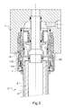
- the figure 1 illustrates a hydraulic block 1 on which a hydraulic filter 2 is reported.
- the filter 2 comprises a tank 3 which receives a filter cartridge 4 which must be changed regularly. The filter is therefore removable.
- the filter 2 comprises a shell 5 which extends around the tank 3 and which is axially locked with respect thereto by a spring washer 6. However, the spring washer 6 does not prevent the shell 5 from rotating 3.
- the ferrule 5 comprises a thread 7 intended to be screwed onto a tapping 8 of the hydraulic block 1.
- a retaining member 100 makes it possible to hold the filter 2 axially when it is screwed onto the hydraulic block 1.
- the retaining member 100 comprises a claw 101 which is fastened to the body by a nut 102 clamped to the bottom of the internal thread. with sufficient torque ensure mechanical strength in use of the thread and especially avoid fretting, so in practice with a significant torque.
- the claw 101 comprises a plurality of flexible fingers terminated by hooks intended to cooperate with a step 9 of the vessel 3.
- the claw 101 has a base 103 which is pressed against a shoulder of the hydraulic block 1 and which protrudes from this shoulder so as to retain a guide 104 in a coaxial cavity of the hydraulic block 1.
- the guide 104 comprises a cylindrical circular wall 105 which extends to receive and axially guide the end of the vessel 3 which covers the wall guide 105 when placing the filter on the hydraulic block 1.
- the guide wall 105 extends opposite the fingers of the claw 101.
- the filter is equipped with a lock 110 in the form of a stepped ring sliding on the outside of the tank 3, and intended to prevent, once the filter in place, the fingers of the claw 101 do not deviate and release axially filter 2.
- the latch 110 is pushed by a spring 111 which bears on a cup 112 stopped on the tank 3 by a rod 113.
- the spring 111 pushes the latch 110 which is supported on a shoulder of the shell 5 to push it in support against the spring washer 6, as visible in the figure 1 .
- the fingers of the claw 101 return to the unflexed position so that the end hooks trap the step 9, which leaves the possibility to the latch 110, pushed by the spring 111 to cap the hooks of the claw 101, so that the fingers of the claw can no longer deviate.
- the filter 2 is then immobilized axially on the hydraulic block 1. It only remains to finish the screwing of the shell 5 so that its redan 10 comes into abutment against the hydraulic block 1. A slight tightening is enough.
- the spring washer 6 is in flexion and thus absorbs the axial mounting clearances necessary for the installation of the filter 2 on the hydraulic block 1.
- the tapping 8 of the hydraulic block 1 receives the nut 102 for fixing the claw 101 of the retaining member 100.
- the nut 102 is tightened at the bottom of the tapping, which induces significant efforts in tapping.
- this nut 102 is normally never disassembled in use.
- the shell 5 is screwed to form a connection which undergoes many screwing and unscrewing in service.
- the shell 5 is only slightly tightened, so that these screwing / unscrewing many do not risk damaging the tapping 8.
- the sealing of the connection between the hydraulic block 1 and the filter 2 is provided on the one hand by a seal 120 disposed between the base of the guide 104 and the hydraulic block 1, and on the other hand by a seal 121 disposed on the guide wall 105 to cooperate with the tank 3. These two seals prevent any flow of hydraulic fluid outside, and in particular on the retaining member 100.
- the guide 104 also forms a seat 130 for a valve 131 mounted to slide axially on a coaxial column 132, with the interposition of a seal 136.
- the valve 131 is pressed against the seat 130 by a spring 133.
- the valve 131 and the column 132 are hollow and thus define a first hydraulic path that leads from the inside of the cartridge 4 to a first port 140 of the block 1.
- the outside of the valve 131 and the outside of the column 132 they define a second hydraulic path leading to a second port 141 of the hydraulic block 1, this path being closed when the valve 131 bears against the seat 130.
- valve 131 When the filter 2 is removed from the hydraulic block 1, the valve 131 is pushed against the seat 130, so that the valve 131 prevents the fluid arriving from the second port 141 from flowing outwards.
- the retaining member has been illustrated as comprising a claw, it is possible to envisage any other axial retaining member, such as for example a ratchet member, with segments, or any other equivalent embodiment.
Landscapes
- Chemical & Material Sciences (AREA)
- Chemical Kinetics & Catalysis (AREA)
- Fluid-Pressure Circuits (AREA)
- Filtration Of Liquid (AREA)
- Filtering Of Dispersed Particles In Gases (AREA)
- Lubrication Details And Ventilation Of Internal Combustion Engines (AREA)
Applications Claiming Priority (1)
| Application Number | Priority Date | Filing Date | Title |
|---|---|---|---|
| FR0801409A FR2928557B1 (fr) | 2008-03-14 | 2008-03-14 | Filtre a cartouche pour aeronef |
Publications (2)
| Publication Number | Publication Date |
|---|---|
| EP2100655A1 true EP2100655A1 (de) | 2009-09-16 |
| EP2100655B1 EP2100655B1 (de) | 2011-11-30 |
Family
ID=39884719
Family Applications (1)
| Application Number | Title | Priority Date | Filing Date |
|---|---|---|---|
| EP09290141A Active EP2100655B1 (de) | 2008-03-14 | 2009-02-27 | Filter mit Filtereinsatz für Flugzeug |
Country Status (10)
| Country | Link |
|---|---|
| US (1) | US7638046B2 (de) |
| EP (1) | EP2100655B1 (de) |
| JP (1) | JP4843062B2 (de) |
| CN (1) | CN101530688B (de) |
| AT (1) | ATE535293T1 (de) |
| AU (1) | AU2009201004B2 (de) |
| BR (1) | BRPI0900377A2 (de) |
| CA (1) | CA2658054C (de) |
| ES (1) | ES2376702T3 (de) |
| FR (1) | FR2928557B1 (de) |
Cited By (1)
| Publication number | Priority date | Publication date | Assignee | Title |
|---|---|---|---|---|
| DE102009030499A1 (de) * | 2009-06-24 | 2010-12-30 | Mann + Hummel Gmbh | Filterverschlusssystem |
Families Citing this family (10)
| Publication number | Priority date | Publication date | Assignee | Title |
|---|---|---|---|---|
| DE102009058177B4 (de) * | 2009-12-15 | 2021-08-05 | Rebs Zentralschmiertechnik Gmbh | Vorrichtung zum Ankoppeln einer eine Schmierstoff-Gas-Strömung führenden Versorgungsleitung an einer Maschine und mit einer solchen Vorrichtung ausgestattete Maschine |
| DE102010015494A1 (de) * | 2010-04-16 | 2011-12-01 | Mahle International Gmbh | Filtereinrichtung |
| US8876168B2 (en) * | 2010-09-17 | 2014-11-04 | The United States Of America As Represented By The Secretary Of The Navy | Adapter ring for pre-filter in chemical, biological and radiological environments |
| US10016711B2 (en) * | 2012-02-22 | 2018-07-10 | Cummins Filtration Ip, Inc. | Installation of correct filter cartridge in fluid filter assembly before allowing assembly to be completed |
| US10293292B2 (en) | 2013-07-23 | 2019-05-21 | Nabtesco Automotive Corporation | Oil separator |
| US11103816B2 (en) * | 2019-05-17 | 2021-08-31 | Rockwell Collins, Inc. | Water filtration device for aircraft galley plumbing system |
| CN113339433B (zh) * | 2020-03-26 | 2025-03-25 | 阳江核电有限公司 | 核电厂碎石过滤器锁车工具以及方法 |
| CN113236748A (zh) * | 2021-05-06 | 2021-08-10 | 中国航发沈阳发动机研究所 | 一种喷嘴及其安装结构 |
| WO2024237985A1 (en) * | 2023-05-12 | 2024-11-21 | Parker-Hannifin Corporation | Filter assembly having a locking mechanism with enhanced engagement features |
| TWI913870B (zh) * | 2024-08-29 | 2026-02-01 | 凱舟濾材股份有限公司 | 過濾單元 |
Citations (4)
| Publication number | Priority date | Publication date | Assignee | Title |
|---|---|---|---|---|
| US3080972A (en) * | 1958-07-28 | 1963-03-12 | Permanent Filter Corp | Filtering component |
| US3283907A (en) * | 1963-08-08 | 1966-11-08 | Bendix Corp | Filter with automatic shut-off valve |
| US5711872A (en) * | 1994-06-15 | 1998-01-27 | Jones; John A. | Reusable oil filter assembly |
| US20040217045A1 (en) | 2003-05-02 | 2004-11-04 | Champion Laboratories, Inc. | Fuel dispenser filter with removable filter media |
Family Cites Families (6)
| Publication number | Priority date | Publication date | Assignee | Title |
|---|---|---|---|---|
| US2932400A (en) * | 1957-04-01 | 1960-04-12 | Purolator Products Inc | Filter unit |
| US2878936A (en) * | 1957-04-05 | 1959-03-24 | Purolator Products Inc | Filter unit |
| GB8407220D0 (en) * | 1984-03-20 | 1984-04-26 | Fram Ind Uk Ltd | Assemblies of screw-thread conjoined parts |
| JPH0360612A (ja) * | 1989-07-27 | 1991-03-15 | Sanyo Electric Co Ltd | サイフォン式紅茶抽出装置 |
| JP3687256B2 (ja) * | 1997-03-14 | 2005-08-24 | 株式会社デンソー | エレメント交換型フィルタ |
| CN200963544Y (zh) * | 2006-11-06 | 2007-10-24 | 林伟胜 | 免拆洗过滤器 |
-
2008
- 2008-03-14 FR FR0801409A patent/FR2928557B1/fr active Active
-
2009
- 2009-02-27 EP EP09290141A patent/EP2100655B1/de active Active
- 2009-02-27 ES ES09290141T patent/ES2376702T3/es active Active
- 2009-02-27 AT AT09290141T patent/ATE535293T1/de active
- 2009-03-09 US US12/400,365 patent/US7638046B2/en active Active
- 2009-03-12 CA CA2658054A patent/CA2658054C/fr not_active Expired - Fee Related
- 2009-03-12 AU AU2009201004A patent/AU2009201004B2/en not_active Ceased
- 2009-03-12 BR BRPI0900377-0A patent/BRPI0900377A2/pt not_active IP Right Cessation
- 2009-03-13 CN CN2009101287421A patent/CN101530688B/zh not_active Expired - Fee Related
- 2009-03-13 JP JP2009061913A patent/JP4843062B2/ja not_active Expired - Fee Related
Patent Citations (4)
| Publication number | Priority date | Publication date | Assignee | Title |
|---|---|---|---|---|
| US3080972A (en) * | 1958-07-28 | 1963-03-12 | Permanent Filter Corp | Filtering component |
| US3283907A (en) * | 1963-08-08 | 1966-11-08 | Bendix Corp | Filter with automatic shut-off valve |
| US5711872A (en) * | 1994-06-15 | 1998-01-27 | Jones; John A. | Reusable oil filter assembly |
| US20040217045A1 (en) | 2003-05-02 | 2004-11-04 | Champion Laboratories, Inc. | Fuel dispenser filter with removable filter media |
Cited By (2)
| Publication number | Priority date | Publication date | Assignee | Title |
|---|---|---|---|---|
| DE102009030499A1 (de) * | 2009-06-24 | 2010-12-30 | Mann + Hummel Gmbh | Filterverschlusssystem |
| US8757393B2 (en) | 2009-06-24 | 2014-06-24 | Mann + Hummel Gmbh | Replaceable filter having a filter closure system |
Also Published As
| Publication number | Publication date |
|---|---|
| AU2009201004A1 (en) | 2009-10-01 |
| EP2100655B1 (de) | 2011-11-30 |
| JP2009222229A (ja) | 2009-10-01 |
| US20090230047A1 (en) | 2009-09-17 |
| ES2376702T3 (es) | 2012-03-16 |
| CN101530688A (zh) | 2009-09-16 |
| FR2928557B1 (fr) | 2010-04-09 |
| CA2658054A1 (fr) | 2009-09-14 |
| AU2009201004B2 (en) | 2013-05-23 |
| FR2928557A1 (fr) | 2009-09-18 |
| CA2658054C (fr) | 2012-04-24 |
| ATE535293T1 (de) | 2011-12-15 |
| CN101530688B (zh) | 2012-02-01 |
| BRPI0900377A2 (pt) | 2009-11-03 |
| US7638046B2 (en) | 2009-12-29 |
| JP4843062B2 (ja) | 2011-12-21 |
Similar Documents
| Publication | Publication Date | Title |
|---|---|---|
| EP2100655B1 (de) | Filter mit Filtereinsatz für Flugzeug | |
| EP2100653B1 (de) | Filtervorrichtung für Luftschiff mit Sicherungs- und Führungsorgan für den Filtereinsatz | |
| EP2100654B1 (de) | Filtervorrichtung für Flugzeug mit Sicherungs- und Führungsorgan für den Filtereinsatz | |
| EP0323298A1 (de) | Kupplungseinrichtung und deren Anwendung, insbesondere bei der Kraftfahrzeuglenkung | |
| WO2007125240A2 (fr) | Chapeau de protection pour récipient et récipient pourvu d'un tel chapeau | |
| EP1241072A1 (de) | Verbindung eines Lenksäulenbügels mit einem Kraftfahrzeuglenkungsritzel | |
| CA2646822A1 (fr) | Ecrou pour la fixation d'un pare-brise d'aeronef et dispositif de fixation d'un pare-brise d'aeronef incorporant ledit ecrou | |
| EP1423285B1 (de) | Montageanordnung von einem sensor auf eine felge eines fahrzeugrads und montageverfahren dafür | |
| EP2354002A1 (de) | Verfahren und Vorrichtung zum Leeren eines Tanks, Tank und mit einer solchen Vorrichtung ausgestattetes Luftfahrzeug | |
| EP0300023A1 (de) | Schnellkupplung. | |
| EP0497647B1 (de) | Ablassschraube für hydraulischen Kreislauf | |
| FR2554543A1 (fr) | Raccord pour montage rapide d'un tube de tuyauterie dans un trou taraude | |
| EP0491603B1 (de) | Verbindungsglied zwischen einem Scheibenwischerarm, insbesondere für Kraftfahrzeug | |
| FR2595126A1 (fr) | Dispositif hydraulique d'actionnement de frein, a rattrapage automatique d'usure, notamment pour vehicule | |
| EP2090818B1 (de) | Ventilkappe für Ventilkörper zum Auffüllen eines Klimaanlagenkreislaufs für Kraftfahrzeug | |
| FR3070136B1 (fr) | Outillage d'assemblage de deux conduits | |
| EP2161193A2 (de) | Bedarfgesteuertes Ventil für Taucher und Organ zur selektiven Flüssigkeitsverbindung | |
| EP0639156B1 (de) | Vorrichtung zum transport von flüssigkeiten mittels schwerkraft einer pumpe | |
| FR2724709A1 (fr) | Dispositif de raccordement pour robinet de recipient de fluide sous pression | |
| FR2694064A1 (fr) | Ensemble formé d'une pièce connectée à un tube, notamment pour circuit de climatisation de véhicule automobile. | |
| FR2990010A1 (fr) | Organe de fixation d'un accessoire sur un support ainsi que du support sur une structure | |
| FR3132940A1 (fr) | Elément de liaison d’un tube de canalisation à un support de palier et turbomachine équipée d’un tel élément de liaison. | |
| EP1104736A1 (de) | Vorrichtung zum Verbinden eines Lenkungsritzels mit einem Bügel | |
| FR2825774A1 (fr) | Raccords de passage de fluide | |
| FR2946556A1 (fr) | Outil de serrage et procede de fixation utilisant l'outil de serrage |
Legal Events
| Date | Code | Title | Description |
|---|---|---|---|
| PUAI | Public reference made under article 153(3) epc to a published international application that has entered the european phase |
Free format text: ORIGINAL CODE: 0009012 |
|
| AK | Designated contracting states |
Kind code of ref document: A1 Designated state(s): AT BE BG CH CY CZ DE DK EE ES FI FR GB GR HR HU IE IS IT LI LT LU LV MC MK MT NL NO PL PT RO SE SI SK TR |
|
| AX | Request for extension of the european patent |
Extension state: AL BA RS |
|
| 17P | Request for examination filed |
Effective date: 20100216 |
|
| 17Q | First examination report despatched |
Effective date: 20100316 |
|
| AKX | Designation fees paid |
Designated state(s): AT BE BG CH CY CZ DE DK EE ES FI FR GB GR HR HU IE IS IT LI LT LU LV MC MK MT NL NO PL PT RO SE SI SK TR |
|
| GRAP | Despatch of communication of intention to grant a patent |
Free format text: ORIGINAL CODE: EPIDOSNIGR1 |
|
| RAP1 | Party data changed (applicant data changed or rights of an application transferred) |
Owner name: MESSIER-BUGATTI-DOWTY |
|
| GRAS | Grant fee paid |
Free format text: ORIGINAL CODE: EPIDOSNIGR3 |
|
| GRAA | (expected) grant |
Free format text: ORIGINAL CODE: 0009210 |
|
| AK | Designated contracting states |
Kind code of ref document: B1 Designated state(s): AT BE BG CH CY CZ DE DK EE ES FI FR GB GR HR HU IE IS IT LI LT LU LV MC MK MT NL NO PL PT RO SE SI SK TR |
|
| REG | Reference to a national code |
Ref country code: GB Ref legal event code: FG4D Free format text: NOT ENGLISH Ref country code: CH Ref legal event code: EP |
|
| REG | Reference to a national code |
Ref country code: IE Ref legal event code: FG4D Free format text: LANGUAGE OF EP DOCUMENT: FRENCH |
|
| REG | Reference to a national code |
Ref country code: DE Ref legal event code: R096 Ref document number: 602009003915 Country of ref document: DE Effective date: 20120301 |
|
| REG | Reference to a national code |
Ref country code: NL Ref legal event code: VDEP Effective date: 20111130 |
|
| REG | Reference to a national code |
Ref country code: ES Ref legal event code: FG2A Ref document number: 2376702 Country of ref document: ES Kind code of ref document: T3 Effective date: 20120316 |
|
| LTIE | Lt: invalidation of european patent or patent extension |
Effective date: 20111130 |
|
| PG25 | Lapsed in a contracting state [announced via postgrant information from national office to epo] |
Ref country code: IS Free format text: LAPSE BECAUSE OF FAILURE TO SUBMIT A TRANSLATION OF THE DESCRIPTION OR TO PAY THE FEE WITHIN THE PRESCRIBED TIME-LIMIT Effective date: 20120330 Ref country code: NO Free format text: LAPSE BECAUSE OF FAILURE TO SUBMIT A TRANSLATION OF THE DESCRIPTION OR TO PAY THE FEE WITHIN THE PRESCRIBED TIME-LIMIT Effective date: 20120229 Ref country code: LT Free format text: LAPSE BECAUSE OF FAILURE TO SUBMIT A TRANSLATION OF THE DESCRIPTION OR TO PAY THE FEE WITHIN THE PRESCRIBED TIME-LIMIT Effective date: 20111130 |
|
| PG25 | Lapsed in a contracting state [announced via postgrant information from national office to epo] |
Ref country code: PT Free format text: LAPSE BECAUSE OF FAILURE TO SUBMIT A TRANSLATION OF THE DESCRIPTION OR TO PAY THE FEE WITHIN THE PRESCRIBED TIME-LIMIT Effective date: 20120330 Ref country code: LV Free format text: LAPSE BECAUSE OF FAILURE TO SUBMIT A TRANSLATION OF THE DESCRIPTION OR TO PAY THE FEE WITHIN THE PRESCRIBED TIME-LIMIT Effective date: 20111130 Ref country code: SE Free format text: LAPSE BECAUSE OF FAILURE TO SUBMIT A TRANSLATION OF THE DESCRIPTION OR TO PAY THE FEE WITHIN THE PRESCRIBED TIME-LIMIT Effective date: 20111130 Ref country code: HR Free format text: LAPSE BECAUSE OF FAILURE TO SUBMIT A TRANSLATION OF THE DESCRIPTION OR TO PAY THE FEE WITHIN THE PRESCRIBED TIME-LIMIT Effective date: 20111130 Ref country code: NL Free format text: LAPSE BECAUSE OF FAILURE TO SUBMIT A TRANSLATION OF THE DESCRIPTION OR TO PAY THE FEE WITHIN THE PRESCRIBED TIME-LIMIT Effective date: 20111130 Ref country code: SI Free format text: LAPSE BECAUSE OF FAILURE TO SUBMIT A TRANSLATION OF THE DESCRIPTION OR TO PAY THE FEE WITHIN THE PRESCRIBED TIME-LIMIT Effective date: 20111130 Ref country code: GR Free format text: LAPSE BECAUSE OF FAILURE TO SUBMIT A TRANSLATION OF THE DESCRIPTION OR TO PAY THE FEE WITHIN THE PRESCRIBED TIME-LIMIT Effective date: 20120301 |
|
| REG | Reference to a national code |
Ref country code: IE Ref legal event code: FD4D |
|
| PG25 | Lapsed in a contracting state [announced via postgrant information from national office to epo] |
Ref country code: CY Free format text: LAPSE BECAUSE OF FAILURE TO SUBMIT A TRANSLATION OF THE DESCRIPTION OR TO PAY THE FEE WITHIN THE PRESCRIBED TIME-LIMIT Effective date: 20111130 |
|
| PGFP | Annual fee paid to national office [announced via postgrant information from national office to epo] |
Ref country code: IT Payment date: 20120228 Year of fee payment: 4 |
|
| PG25 | Lapsed in a contracting state [announced via postgrant information from national office to epo] |
Ref country code: BG Free format text: LAPSE BECAUSE OF FAILURE TO SUBMIT A TRANSLATION OF THE DESCRIPTION OR TO PAY THE FEE WITHIN THE PRESCRIBED TIME-LIMIT Effective date: 20120229 Ref country code: EE Free format text: LAPSE BECAUSE OF FAILURE TO SUBMIT A TRANSLATION OF THE DESCRIPTION OR TO PAY THE FEE WITHIN THE PRESCRIBED TIME-LIMIT Effective date: 20111130 Ref country code: SK Free format text: LAPSE BECAUSE OF FAILURE TO SUBMIT A TRANSLATION OF THE DESCRIPTION OR TO PAY THE FEE WITHIN THE PRESCRIBED TIME-LIMIT Effective date: 20111130 Ref country code: CZ Free format text: LAPSE BECAUSE OF FAILURE TO SUBMIT A TRANSLATION OF THE DESCRIPTION OR TO PAY THE FEE WITHIN THE PRESCRIBED TIME-LIMIT Effective date: 20111130 Ref country code: IE Free format text: LAPSE BECAUSE OF FAILURE TO SUBMIT A TRANSLATION OF THE DESCRIPTION OR TO PAY THE FEE WITHIN THE PRESCRIBED TIME-LIMIT Effective date: 20111130 Ref country code: DK Free format text: LAPSE BECAUSE OF FAILURE TO SUBMIT A TRANSLATION OF THE DESCRIPTION OR TO PAY THE FEE WITHIN THE PRESCRIBED TIME-LIMIT Effective date: 20111130 |
|
| BERE | Be: lapsed |
Owner name: MESSIER-BUGATTI-DOWTY Effective date: 20120228 |
|
| PG25 | Lapsed in a contracting state [announced via postgrant information from national office to epo] |
Ref country code: RO Free format text: LAPSE BECAUSE OF FAILURE TO SUBMIT A TRANSLATION OF THE DESCRIPTION OR TO PAY THE FEE WITHIN THE PRESCRIBED TIME-LIMIT Effective date: 20111130 Ref country code: PL Free format text: LAPSE BECAUSE OF FAILURE TO SUBMIT A TRANSLATION OF THE DESCRIPTION OR TO PAY THE FEE WITHIN THE PRESCRIBED TIME-LIMIT Effective date: 20111130 |
|
| REG | Reference to a national code |
Ref country code: AT Ref legal event code: MK05 Ref document number: 535293 Country of ref document: AT Kind code of ref document: T Effective date: 20111130 |
|
| PG25 | Lapsed in a contracting state [announced via postgrant information from national office to epo] |
Ref country code: MC Free format text: LAPSE BECAUSE OF NON-PAYMENT OF DUE FEES Effective date: 20120229 |
|
| PLBE | No opposition filed within time limit |
Free format text: ORIGINAL CODE: 0009261 |
|
| STAA | Information on the status of an ep patent application or granted ep patent |
Free format text: STATUS: NO OPPOSITION FILED WITHIN TIME LIMIT |
|
| 26N | No opposition filed |
Effective date: 20120831 |
|
| REG | Reference to a national code |
Ref country code: DE Ref legal event code: R097 Ref document number: 602009003915 Country of ref document: DE Effective date: 20120831 |
|
| PG25 | Lapsed in a contracting state [announced via postgrant information from national office to epo] |
Ref country code: BE Free format text: LAPSE BECAUSE OF NON-PAYMENT OF DUE FEES Effective date: 20120228 |
|
| PG25 | Lapsed in a contracting state [announced via postgrant information from national office to epo] |
Ref country code: AT Free format text: LAPSE BECAUSE OF FAILURE TO SUBMIT A TRANSLATION OF THE DESCRIPTION OR TO PAY THE FEE WITHIN THE PRESCRIBED TIME-LIMIT Effective date: 20111130 |
|
| PG25 | Lapsed in a contracting state [announced via postgrant information from national office to epo] |
Ref country code: MK Free format text: LAPSE BECAUSE OF FAILURE TO SUBMIT A TRANSLATION OF THE DESCRIPTION OR TO PAY THE FEE WITHIN THE PRESCRIBED TIME-LIMIT Effective date: 20111130 |
|
| PGFP | Annual fee paid to national office [announced via postgrant information from national office to epo] |
Ref country code: ES Payment date: 20130227 Year of fee payment: 5 |
|
| PG25 | Lapsed in a contracting state [announced via postgrant information from national office to epo] |
Ref country code: FI Free format text: LAPSE BECAUSE OF FAILURE TO SUBMIT A TRANSLATION OF THE DESCRIPTION OR TO PAY THE FEE WITHIN THE PRESCRIBED TIME-LIMIT Effective date: 20111130 |
|
| PG25 | Lapsed in a contracting state [announced via postgrant information from national office to epo] |
Ref country code: MT Free format text: LAPSE BECAUSE OF FAILURE TO SUBMIT A TRANSLATION OF THE DESCRIPTION OR TO PAY THE FEE WITHIN THE PRESCRIBED TIME-LIMIT Effective date: 20111130 |
|
| REG | Reference to a national code |
Ref country code: CH Ref legal event code: PL |
|
| PG25 | Lapsed in a contracting state [announced via postgrant information from national office to epo] |
Ref country code: CH Free format text: LAPSE BECAUSE OF NON-PAYMENT OF DUE FEES Effective date: 20130228 Ref country code: LI Free format text: LAPSE BECAUSE OF NON-PAYMENT OF DUE FEES Effective date: 20130228 |
|
| PG25 | Lapsed in a contracting state [announced via postgrant information from national office to epo] |
Ref country code: TR Free format text: LAPSE BECAUSE OF FAILURE TO SUBMIT A TRANSLATION OF THE DESCRIPTION OR TO PAY THE FEE WITHIN THE PRESCRIBED TIME-LIMIT Effective date: 20111130 |
|
| PG25 | Lapsed in a contracting state [announced via postgrant information from national office to epo] |
Ref country code: LU Free format text: LAPSE BECAUSE OF NON-PAYMENT OF DUE FEES Effective date: 20120227 |
|
| PG25 | Lapsed in a contracting state [announced via postgrant information from national office to epo] |
Ref country code: HU Free format text: LAPSE BECAUSE OF FAILURE TO SUBMIT A TRANSLATION OF THE DESCRIPTION OR TO PAY THE FEE WITHIN THE PRESCRIBED TIME-LIMIT Effective date: 20090227 |
|
| REG | Reference to a national code |
Ref country code: ES Ref legal event code: FD2A Effective date: 20150331 |
|
| PG25 | Lapsed in a contracting state [announced via postgrant information from national office to epo] |
Ref country code: ES Free format text: LAPSE BECAUSE OF NON-PAYMENT OF DUE FEES Effective date: 20140228 |
|
| REG | Reference to a national code |
Ref country code: DE Ref legal event code: R082 Ref document number: 602009003915 Country of ref document: DE Representative=s name: SCHAUMBURG & PARTNER PATENTANWAELTE GBR, DE Ref country code: DE Ref legal event code: R082 Ref document number: 602009003915 Country of ref document: DE Representative=s name: SCHAUMBURG & PARTNER PATENTANWAELTE MBB, DE Ref country code: DE Ref legal event code: R082 Ref document number: 602009003915 Country of ref document: DE Representative=s name: SCHAUMBURG UND PARTNER PATENTANWAELTE MBB, DE |
|
| REG | Reference to a national code |
Ref country code: FR Ref legal event code: PLFP Year of fee payment: 8 |
|
| PG25 | Lapsed in a contracting state [announced via postgrant information from national office to epo] |
Ref country code: IT Free format text: LAPSE BECAUSE OF NON-PAYMENT OF DUE FEES Effective date: 20140227 |
|
| REG | Reference to a national code |
Ref country code: FR Ref legal event code: PLFP Year of fee payment: 9 |
|
| REG | Reference to a national code |
Ref country code: FR Ref legal event code: CD Owner name: MESSIER-BUGATTI-DOWTY, FR Effective date: 20170518 |
|
| REG | Reference to a national code |
Ref country code: FR Ref legal event code: PLFP Year of fee payment: 10 |
|
| PGFP | Annual fee paid to national office [announced via postgrant information from national office to epo] |
Ref country code: DE Payment date: 20220119 Year of fee payment: 14 |
|
| REG | Reference to a national code |
Ref country code: DE Ref legal event code: R119 Ref document number: 602009003915 Country of ref document: DE |
|
| PG25 | Lapsed in a contracting state [announced via postgrant information from national office to epo] |
Ref country code: DE Free format text: LAPSE BECAUSE OF NON-PAYMENT OF DUE FEES Effective date: 20230901 |
|
| PGFP | Annual fee paid to national office [announced via postgrant information from national office to epo] |
Ref country code: GB Payment date: 20260219 Year of fee payment: 18 |
|
| PGFP | Annual fee paid to national office [announced via postgrant information from national office to epo] |
Ref country code: FR Payment date: 20260219 Year of fee payment: 18 |