EP2100748B1 - Dossier suspendu - Google Patents
Dossier suspendu Download PDFInfo
- Publication number
- EP2100748B1 EP2100748B1 EP08004711A EP08004711A EP2100748B1 EP 2100748 B1 EP2100748 B1 EP 2100748B1 EP 08004711 A EP08004711 A EP 08004711A EP 08004711 A EP08004711 A EP 08004711A EP 2100748 B1 EP2100748 B1 EP 2100748B1
- Authority
- EP
- European Patent Office
- Prior art keywords
- supporting
- side wall
- intermediate wall
- connecting device
- suspension
- Prior art date
- Legal status (The legal status is an assumption and is not a legal conclusion. Google has not performed a legal analysis and makes no representation as to the accuracy of the status listed.)
- Not-in-force
Links
- 239000000725 suspension Substances 0.000 claims description 47
- 230000015572 biosynthetic process Effects 0.000 abstract 1
- 239000000835 fiber Substances 0.000 abstract 1
- 238000005452 bending Methods 0.000 description 12
- 238000005192 partition Methods 0.000 description 12
- 239000000463 material Substances 0.000 description 3
- XEEYBQQBJWHFJM-UHFFFAOYSA-N Iron Chemical compound [Fe] XEEYBQQBJWHFJM-UHFFFAOYSA-N 0.000 description 2
- 206010041953 Staring Diseases 0.000 description 2
- 238000010276 construction Methods 0.000 description 2
- 238000012986 modification Methods 0.000 description 2
- 230000004048 modification Effects 0.000 description 2
- 239000004033 plastic Substances 0.000 description 2
- 238000007665 sagging Methods 0.000 description 2
- 230000006978 adaptation Effects 0.000 description 1
- 238000006243 chemical reaction Methods 0.000 description 1
- 239000004744 fabric Substances 0.000 description 1
- 238000009434 installation Methods 0.000 description 1
- 229910052742 iron Inorganic materials 0.000 description 1
- 238000002955 isolation Methods 0.000 description 1
- 239000002985 plastic film Substances 0.000 description 1
- 229920006255 plastic film Polymers 0.000 description 1
- 239000002689 soil Substances 0.000 description 1
- 239000007787 solid Substances 0.000 description 1
- 239000011343 solid material Substances 0.000 description 1
Images



Classifications
-
- B—PERFORMING OPERATIONS; TRANSPORTING
- B42—BOOKBINDING; ALBUMS; FILES; SPECIAL PRINTED MATTER
- B42F—SHEETS TEMPORARILY ATTACHED TOGETHER; FILING APPLIANCES; FILE CARDS; INDEXING
- B42F15/00—Suspended filing appliances
- B42F15/02—Suspended filing appliances in concertina form
-
- B—PERFORMING OPERATIONS; TRANSPORTING
- B42—BOOKBINDING; ALBUMS; FILES; SPECIAL PRINTED MATTER
- B42F—SHEETS TEMPORARILY ATTACHED TOGETHER; FILING APPLIANCES; FILE CARDS; INDEXING
- B42F15/00—Suspended filing appliances
- B42F15/04—Backs or the like therefor
Definitions
- the invention relates to a suspension file according to the preamble of claim 1.
- Hanging file directories are a widespread sorting system for paper storage. They offer the possibility to deposit very different documents, usually paper-based printouts, drawings, photos etc. easily and quickly accessible.
- Suspension filing usually include so-called suspension files or hanging bags with two side walls, which are lying down on a common bending or bending line directly or with the interposition of a usually reinforced, in use rather horizontally coming bottom portion connected to each other.
- hanger iron brackets are often used, which are provided at their opposite end sides with, for example, downwardly projecting lugs and thereby overlap lateral mounting rails or mounting rail sections. If necessary, the suspended hanging bags or hanging files can be easily moved along the hanging rail.
- the folders are usually designed lid-like, so made of cardboard, which they have a certain rigidity, but nevertheless also in a known manner are bendable.
- hanging file systems which have more tissue-like, more or less freely sagging pockets, as for example from the DE 298 21 381 U1 or the CH 183 700 is known.
- the hanging bags or folders each have only a limited storage and storage space.
- so-called hanging collectors have been proposed, the different widths, usually reinforced with plastic back or floors between the side walls have, so that the pendent collector thus formed in front view not V-shaped, but rather U-shaped with a solid horizontal bottom is formed.
- a hanging file in the form of a hanging bag which has a first and second side wall with an intermediate wall wherein the intermediate wall between a first and a second side wall between a vertically oriented position can be folded into a position pivoted about 90 °, wherein it forms a bottom for the pocket in this. Further, a supporting or connecting device is provided, in which the folded acting as a floor intermediate wall is held.
- the hanging file can be designed so that the support or suspension device is not attached to the intermediate wall.
- hanging bag or suspension file which usually comprises two lateral, bottom converging, interconnected side wall sections to change with a simple handle so that the same Suspension file provides a much larger recording space.
- the intermediate wall can be pivoted between an at least substantially vertical orientation and an open position which is folded over in the horizontal position.
- the intermediate wall acts as the second side wall opposite the first side wall and forming the respective hanging pocket, since this intermediate wall is connected directly or indirectly, for example under a bottom wall section, to the first side wall, as in conventional suspension file systems Quasi through the first side wall and the intermediate wall is formed in a side view V-shaped or U-shaped hanging bag comparable to the conventional hanging bags.
- this intermediate wall can be folded away from the first side wall in an approximately horizontal position, so that this intermediate wall now comes to lie a bottom wall portion between the first side wall and a now exposed next side wall of the hanging file.
- a receiving space is now formed whose width is greater by a multiple than in the collapsed state.
- an intermediate wall is provided, which is connected via a connecting line located below directly or indirectly with the first side wall.
- the intermediate wall of a more vertical orientation (or one example, light angled divergent orientation relative to the first side wall) in a contrast, further open, preferably foldable second position, about which it is at least approximately aligned horizontally and now forms the bottom of such a hanging bag.
- a supporting and connecting device is further provided which acts between the first and the second side wall, in particular between the intermediate wall and the second side wall and ensures that the intermediate wall is held in its function as a ground in a corresponding horizontal position.
- the peculiarity of the solution according to the invention lies in the fact that the distance between the first and the second side wall with folded intermediate wall, which forms the bottom in the folded position, is greater than the width of the intermediate wall. This has the consequence that the entire bottom surface between the first and second side wall is formed by the folded intermediate wall on the one hand and on the other by an upwardly exposed portion of the associated supporting and / or connecting device. In other words, this measure with a comparatively short side wall nevertheless a wide pocket can be formed.
- the second side wall of a hanging bag simultaneously forms the first side wall of a subsequent hanging bag, whereby the entire structure can be simplified once again.
- each hanging bag with two side walls and the one in between, convertible partition as an independent unit.
- Such hanging collectors could therefore be suspended individually according to a suspended track system.
- units having a plurality of hanging pockets are preferred, which are designed as a unit that can be handled in common, in which each subsequent side wall simultaneously represents the first side wall of a subsequent second hanging bag.
- the supporting and connecting device for supporting and holding the folded in its horizontal position intermediate wall (in which it forms the bottom of a suspension file) can be realized by different measures.
- a supporting and connecting device which consists of a solid material and, if necessary, supports supporting forces and can not be wound up in a ribbon.
- an attachment and in particular supporting system for example, at the lower connecting line between the first side wall and the associated partition wall into consideration.
- An attachment of the support / hanger is preferably but also on the side wall portion, in particular alone on the side wall portion possible, in the region below the connecting line to the first side wall and above the upper edge of the partition. It proves to be particularly advantageous if the example plate-shaped supporting and connecting device is preferably mounted halfway up the intermediate wall section. The opposite side is then preferably provided at the lower boundary of a subsequent side wall.
- Deviating from but the attachment may also be provided elsewhere, for example at any point above the underlying connection line (where the partition is connected to the first side wall), in particular at the upper edge of the convertible partition, wherein the opposite side of the support - And connecting device is then preferably provided at half the height of the convertible partition on the adjacent next side wall.
- a hanging bag according to the invention is in a schematic side view in FIG. 11 shown.
- FIGS. 1 to 10 and FIG. 12 and 13 examples are also shown which, on the one hand, serve to facilitate the understanding of the invention and, on the other hand, include or may at least include details which, if appropriate, may also be of importance in the solution according to the invention.
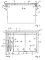
- an overhead shelf 1 is shown as it may be provided as part of a shelving system, a filing cabinet, a container.
- each a support rail 5 is mounted, which may be configured in cross-section, for example, at least approximately C-shaped, namely with one of the plate bottom 1a downwardly extending retaining web 5a, with a downwardly adjoining and extending from the outer edge 1b and 1c away connecting portion 5b and an adjoining over a small distance upwardly projecting holding portion 5c.
- a corresponding hanging file 9 includes, for example, hanging bags 11, which are sometimes also referred to as hanging files or hanging collectors.
- Such hanging bags usually comprise two side walls, which are connected in front view V-shaped or U-shaped with each other, wherein at the two side walls each lying above a support and / or hanging device 15 is provided, often in the form of a support rail 15 a, which projects beyond the width of the hanging pockets 11 and is provided at its opposite ends, for example, with downwardly projecting engagement lugs 15 b.
- the first side walls 21 and second side walls 25, which are explained below, are connected at their respective edge or edge region 21b or 25b to the support and / or suspension device 15 mentioned above, often in the form of a so-called support rail 15a, via which the hanging pockets can be hung on a corresponding holding mechanism.
- a hanging bag thus formed can then be easily hung in a known manner by lifting, twisting and lowering in a suspension rail system 5 thus formed.
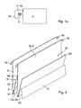
- a longitudinal member 5 ' may be provided, which is designed for example rod-shaped and on the, as with reference to the section of FIG. 1a is shown, the suspension lugs 15b of the support rail 15a overlap and can be hung.
- the aforementioned hanging bags 11 can be hung on other, with respect to a hanging bag 11 rather centrally provided support and support rails.
- the type of suspension and the design plays no role for the further type of the invention designed suspension file.
- FIG. 2 Reference is made in the example of a furniture-like container, cabinet, sideboard 6 etc. is reproduced in the section, namely with two side walls 17, between which the in FIG. 1 already mentioned shelf 1 extends with the provided on the bottom support rails 5.
- the hanging file 9 explained below is hung.
- FIG. 2 is a schematic side view of a hanging file with, for example, five contiguous hanging bags 11 reproduced, wherein the in FIG. 2 the leftmost two hanging bags 11 are completely unused pushed together, the subsequent third hanging bag in their only a small storage space offering narrow configuration or open position can be seen, whereas the two right-hanging bags 11 by moving a subsequently explained in more detail intermediate wall 23rd are shown in their maximum storage space bidding configuration.
- FIG. 3 are two hanging bags 11 (as they are in FIG. 2 used) in isolation to better illustrate the operation.
- the hanging bag 11 in each case in frontal view (as in FIG. 2 reproduced) a first side wall 21, thereafter a folding intermediate wall 23, and a next second side wall 25, according to the embodiment of Figures 2 and 3 at the same time forms the first side wall 21 for a next subsequent hanging bag 11.
- the intermediate wall 23 is at its lower longitudinal side 23a with the lower longitudinal side 21a of the first Side wall 21 connected to form a connecting line 27, which is also referred to below as a bending or pivot axis 27.
- a hanging bag 11 is held in each case by their left in the figures first side wall 21 by the respective support rail 5, in which the mentioned support and / or suspension device 15, 15a can be hung with the outer hanger 15b.
- the foldable intermediate wall 23 runs - if the relevant hanging bag 11, such as in FIG. 2 lying left, is completely pushed together - parallel or quasi parallel to the first side wall 13, so usually at least approximately vertically, so that between the first side wall 21 and the convertible intermediate wall 23 itself provided receiving space 29 is completely minimized.
- Each hanging bag 11 can be opened to increase the storage space 29 by each one shown in the figures (left there) first side wall 21 a next hanging bag 11 is moved at least a degree to the right, so that the so-called intermediate wall 23 of a preceding (So left in the drawings) hanging bag 11 to the right about its underlying bending axis 27 can be pivoted or tilted.
- this can be aligned, for example, with a small angle of for example 1 ° to 20 ° (and each angular range therebetween) slightly divergent to the associated first side wall 21 of the hanging bag to in this slightly open position small dimensioned receiving space 29 as a storage space for a variety of papers, prints, films, etc. to provide.
- Supporting and / or connecting device 31 shown, which at its opposite longitudinal sides, in the illustrated embodiment, on the connecting line 27 on the one hand and on the opposite side on the corresponding lower longitudinal side 25a with the second Side wall 25 of a subsequent second hanging bag 11 attached to the other and / or attached.
- This supporting and / or connecting device 31 can be, for example, a flexible (bendable, deformable, etc.) supporting and / or connecting device 131, for example in the form of a band, a fabric band, a plastic band or a plastic film etc.
- this flexible supporting and / or connecting device 131 corresponds in the illustrated embodiment, the height (and thus the width) of the convertible intermediate wall 23 (ie the distance between the bending axis 27 and the outer or upper edge 23b of the intermediate wall 23), or at least approximately the height of the convertible partition 23.
- each hanging bag 11 the right, ie second, side wall 25 lying in the figures can be pushed away from the first side wall 21 lying on the left side of the figures until, as shown in FIG. 2 the flexible supporting and / or connecting device 131 running between two adjacent connecting lines 27 (that is, between in each case a first and a second side wall) is completely tensioned, that is, extends in the longitudinal extent (lying more or less in the horizontal plane). Further, the successive first side walls 21 of two consecutive hanging bags 11 can not be removed from each other. Until reaching this pushed apart position, the convertible intermediate wall 23 of its in Figures 2 and 3 reproduced raised, more vertical orientation can be pivoted down to the horizontal plane. In this position - as for the in FIG.
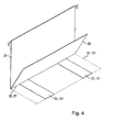
- the flexible supporting and / or connecting device 131 may have a depth, ie a length parallel to the connecting line 27, the length of a hanging bag 11, ie the length of the first side wall 21, the length of the intermediate wall 23, the length of the second side wall 25 etc corresponds to (as in FIG. 4 shown in dashed lines is, where FIG. 4 in a schematic perspective view, only a first side wall 21 and an associated intermediate wall 23 and the outgoing from the connecting line 27 supporting and / or connecting device 31 reproduces). But it may also be provided a narrower connection band or, for example, two offset in the longitudinal direction of a connecting line 27 lying bands or more, as also in FIG. 4 is shown.
- the flexible supporting and / or connecting device 31, 131 was fastened in each case to the connecting line 27 between a first side wall 21 and the foldable intermediate wall 23 of a first hanging bag 11 and a next hanging bag 11.
- the respective supporting and / or connecting device was connected to a first side wall 21 and / or the intermediate wall 23 along a first connecting line 35 and on the opposite side along a second fastening line 37 with the subsequent second side wall 25, wherein the fastening lines 35 and 37 each coincide with the bending line 27 between a first side wall 21 and the associated intermediate wall 23 in this embodiment.
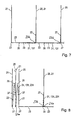
- the flexible supporting and / or connecting device 31, 131 is mounted at half the height of the convertible intermediate wall 23 with this, namely along the attachment and / or Verschwenkline 35 (FIGS. FIG. 5 ).
- closed hanging bag 11 according to FIG. 6 There in the two shown on the left pushed together, so closed hanging pockets 11
- the flexible supporting and / or connecting device 31, 131 then runs, as in FIG FIG.
- FIG. 6 is shown for the right-lying open hanging bag, from the attachment line 35 on the outside or bottom of the here forming the bottom partition wall 23 to the attachment line 37 of the next, so right lying second side wall 25th
- FIG. 6 schematically this variant is shown, in FIG. 6 next to the two (closed) hanging pockets pushed together on the left, the following third hanging bag is currently in an intermediate position, in which the convertible intermediate wall 23 is displaced straight into the lowered horizontal position according to arrow representations 38 and 38 '(which in FIG FIG. 6 right next pocket is already fully unfolded), in which case this flexible supporting and / or connecting device 31, 131 is shown in its end position.
- the supporting and / or connecting device 31 can also be fastened to a next side wall 21 of a next hanging bag 11 (lying on the outside) above the lower connecting line 27.
- the flexible support and / or Connecting device 31, 131 also again between the attachment line 35 on the one hand and the other attachment line 37 to the other, wherein the attachment line 35, for example - as in FIG. 7 is shown - may be provided between the lower connecting line 27 and the upper free edge 23 b of the convertible intermediate wall 23.
- the second attachment line 37 on the right-hand second side wall 25 is provided, for example, above the bottom folded in horizontal position 23, ie above the underlying boundary lines 21a of the side walls 21.
- the flexible support and / or connection means 131 to extend to the edge 23b of the folded in horizontal position intermediate wall 23, and then continue to run at an angle 90 'up to the above provided therefor attachment line 37 on the second side wall 25 ( FIG. 8 ).
- the supporting and / or connecting device 31 may for example also be attached to the upper edge 23b of the convertible intermediate wall 23, which lends itself here, then the opposite attachment of the supporting and / or connecting device 31 at half height, based on the width of the intermediate wall 23 to attach to the next first side wall 21 of the next hanging bag 11.
- the flexible support and / or connection means 31, 131 extends from the next side wall 21 in the vertical direction up to the upper edge of the intermediate wall 23, whereas in the unfolded state of the intermediate wall 23 then the flexible support and / or connection means 31, 131 runs vertically downwards and acting as a floor intermediate wall 23 stops in this horizontal position. Both variants are shown in the schematic side view FIG. 8 played.
- a more rigid or only partially elastic connection means 231 may be provided, in particular in the embodiments of the FIGS. 5, 6 or 8th ,
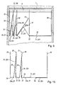
- FIG. 9 Based on FIG. 9 is shown schematically, but also in a variant comparable to those as in FIG. 2 and 3 has been shown, a quasi-firm, rather non-flexible supporting and / or connecting device 231 may be provided, which has lying above a bending or hinge line 231a.
- the supporting and / or connecting means 31, 131 could be folded in the folded state of the hanging pockets in the manner of an upside down V, and would in the open position of a bag folded in horizontal position Between wall 23 then be expanded accordingly parallel to it.
- the supporting and / or connecting means 31, 231 is hingedly or flexibly secured to the underside of the intermediate wall 23.
- the supporting and / or connecting device 31, 231 is fastened on the opposite side, for example on the lower connecting line 27 on the subsequent second side wall 25. This results in a firm "tension" in a fully open position, in which the supporting and / or connecting device 31, 231 rests parallel and / or over the entire surface of the adjacent portion of the intermediate wall 23.
- the respective intermediate wall 23 does not have to be connected directly to an adjacent first side wall 21 via a connecting line 27, but that a hanging bag may already have a specific (usually rather narrow) back or bottom 24 from home
- a connecting line 27 is offset, for example, to the first side wall 21 at the in FIG. 10 right lying and transverse to the plane of the drawing longitudinal side 24a of this back or bottom section 24.
- supporting and / or connecting means 31, 131 and 231 are provided.
- a rather rigid support and support and / or connection device 231 is shown, which is hingedly mounted and supported at the lower end of a subsequent second side wall 25 on the one hand and on the folding intermediate wall 23 to the other.
- the weight of a hanging bag 11 can be accommodated not only by the first side wall 21 but also jointly by the first and second side wall 21, 25, even in a collapsed position.
- the second side wall 25 simultaneously represents the first side wall 21 of a following hanging pocket 11 in the case of a linked suspension file.
- the width or height of the convertible intermediate wall 23 (ie, the distance between the bending line 27 and the upper free edge 23b) may be smaller than the maximum distance between the bending line 27, the same time the first attachment line 37 for the support - and / or connecting means 31, 231 represents, and the in FIG. 11 right next connecting line 27, at the attachment line 37 is formed on the next side wall 21, 25. Because in this case, an at least narrow strip of the bottom surface is then formed by the upwardly exposed supporting and / or connecting device 31, 231, between the free edge 23b of the folded intermediate wall 23 and the in FIG. 11 right next to it lying next side wall 21, 25 is exposed.
- the depth of the supporting and / or connecting device should also correspond in this case in particular to the depth of a corresponding pocket 11, thereby forming a closed bottom surface.
- adjustable hanging file can be designed not only in the form of several contiguous hanging bags, but also in the form of independently usable individual hanging bags.
- each first Side wall 21 and an associated intermediate wall 23 and the flexible or rather rigid, non-flexible support and / or connection means 31, 131, 231 further provided a subsequent second side wall 25 which is formed in principle as the basis of the Also in this case, the corresponding supporting and / or connecting device 31, 131, 231 would be supported on one side on the first side wall or preferably the intermediate wall 23 and / or fastened and at its opposite end on the second side wall 25. Construction and operation is otherwise identical.
- the other embodiments show, however, that it is basically not necessary to design the hanging bags individually, but that a "chained" solution is possible, in the quasi the second side wall 25 of a single hanging bag 11 with a subsequent first side wall 21 of a subsequent second pocket 11 merged into a single side wall.
- the embodiments have been designed so that the lower longitudinal side 23a of the intermediate wall 23 or the lower longitudinal side 21a of the first side wall 21 coincide and form the so-called connecting line 27.
- the first side wall 21 and / or the intermediate wall 23 may also project beyond the mentioned connecting line 27 downwards and be extended. The functionality is not affected by this.
- the illustrated embodiments show variants in which the convertible intermediate wall 23 is held in its at least approximately horizontal position (ie at maximum open hanging pocket 11) in different ways.
- the foldable intermediate wall 23 rests on the supporting and / or connecting device 31, which runs directly parallel and underneath. Since the length (or width) between two first side walls 21 corresponds to the height of an intermediate wall 23, therefore, the free edge 23b of the intermediate wall 23 is located directly next to the attachment line 27 on the (flexible) attached to a next first or second side wall 21, 25 Supporting and / or connecting device 31, 131, so it can not fall further down here.
- intermediate walls 23 could be provided on the respective intermediate walls 23 (or 25) and an at least slightly dimensioned, projecting in the direction of an intermediate wall 23 support edge or a protruding support bracket or other projections 21c, as shown in an enlarged detail in FIG FIG. 13 is reproduced.
- the length of the supporting and / or connecting device 31, 131 would be the maximum distance between two side walls 21 or a first and a second one Side wall 21, 25 limited so that then the convertible intermediate wall 23 rests in the region of its free edge 23b on this support angle, this support edge or other projections 21c and here the support forces directly into the provided with the support bracket or the support edge or other projections 21c side wall 21 are initiated.
- a support of the convertible intermediate wall 23 realized in that the free edge 23b of the convertible intermediate wall 23 on the supporting and / or connecting device 31, 131, 231 quasi “suspended", and is held in its horizontal end position.
Landscapes
- Supports Or Holders For Household Use (AREA)
- Purses, Travelling Bags, Baskets, Or Suitcases (AREA)
- Molds, Cores, And Manufacturing Methods Thereof (AREA)
- Vehicle Step Arrangements And Article Storage (AREA)
- Eye Examination Apparatus (AREA)
- Sheet Holders (AREA)
- Information Retrieval, Db Structures And Fs Structures Therefor (AREA)
Claims (17)
- Dossier suspendu sous la forme d'une poche suspendue (11), comprenant les éléments techniques suivants :- la poche suspendue (11) comprend une première et une deuxième paroi latérale (21, 25),- il est prévu une paroi intermédiaire (23),- la paroi intermédiaire (23) est prévue entre la première et la deuxième paroi latérale (21, 25),- la paroi intermédiaire (23) est reliée, via une ligne de liaison (27) située en bas, directement ou indirectement à la première paroi latérale (21),- la paroi intermédiaire (23) est capable de pivoter depuis une orientation parallèle à la première paroi latérale (21) et/ou verticale ou au moins une orientation qui s'étend de façon majoritaire avec une composante verticale, jusque dans une seconde situation rabattue par rapport à la première, dans laquelle elle est orientée en direction horizontale ou au moins approximativement en direction horizontale en formant un fond pour la poche suspendue (11), et- il est prévu un dispositif de soutien et de liaison (31 ; 131, 231) qui est fixé d'une part à la première paroi latérale (21) et/ou à la paroi intermédiaire (23) rabattable, et d'autre part à la deuxième paroi latérale (25) de telle façon que la paroi intermédiaire rabattable (23) est maintenue dans sa fonction à titre de fond au moyen de ce dispositif, caractérisé par les autres caractéristiques suivantes :- lorsque la paroi intermédiaire (23 est rabattue en formant un fond pour une poche suspendue (11), la distance entre la première et la deuxième paroi latérale (21, 25) est supérieure à la largeur de la paroi intermédiaire (23), et- la totalité de la surface du fond entre la première et la deuxième paroi latérale (21, 25) est formée par la paroi intermédiaire rabattue (23) et par une région partielle, situé dégagée vers le haut, du dispositif de soutien et de liaison (31 ; 131, 231) associé.
- Dossier suspendu selon la revendication 1, caractérisé en ce que seule la première et la deuxième paroi latérale (21, 25) sont équipées en partie haute d'un dispositif de support et d'accrochage (15), et la paroi intermédiaire rabattable (23) est dépourvue de dispositif de support et d'accrochage à sa partie supérieure.
- Dossier suspendu selon la revendication 1 ou 2, caractérisé en ce que le dispositif de soutien et de liaison (31 ; 131, 231) est monté et fixé d'une part à la face inférieure et en particulier sur le côté longitudinal inférieur (21a) de la première paroi latérale (21), et/ou à la face inférieure, en particulier sur le côté longitudinal inférieur (23a) de la paroi intermédiaire rabattable (23).
- Dossier suspendu selon l'une des revendications 1 à 3, caractérisé en ce que le dispositif de soutien et de liaison (31 ; 131, 231) est fixé sur la paroi intermédiaire rabattable (23).
- Dossier suspendu selon la revendication 4, caractérisé en ce que le dispositif de soutien et de liaison (31 ; 131, 231) est fixé sur la face extérieure ou inférieure, tournée vers la seconde paroi latérale (25), de la paroi intermédiaire rabattable (23), de préférence au-dessus du côté longitudinal inférieur (23a) et au-dessous de la bordure longitudinale supérieure (23b).
- Dossier suspendu selon la revendication 4 ou 5, caractérisé en ce que le dispositif de soutien et de liaison (31 ; 131, 231) est fixé sur la paroi intermédiaire rabattable (23) à mi-hauteur de celle-ci.
- Dossier suspendu selon l'une des revendications 1 à 6, caractérisé en ce que le dispositif de soutien et de liaison (31 ; 131, 231) est relié à la paroi intermédiaire rabattable (23) à la bordure longitudinale supérieure (23b) de celle-ci.
- Dossier suspendu selon l'une des revendications 1 à 7, caractérisé en ce que le dispositif de soutien et de liaison (31 ; 131, 231) est fixé au niveau du côté longitudinal inférieur (25a) de la deuxième paroi latérale (25).
- Dossier suspendu selon l'une des revendications 1 à 7, caractérisé en ce que le dispositif de soutien et de liaison (31 ; 131, de 131) est fixé à la deuxième paroi latérale (25) au-dessus du côté longitudinal inférieur (25a).
- Dossier suspendu selon la revendication 9, caractérisé en ce que le dispositif de soutien et de liaison (31 ; 131, 231) est fixé sur la deuxième paroi latérale (25) à une distance au-dessus du côté longitudinal inférieur (25a) de celle-ci, qui correspond à la moitié de la hauteur de la paroi intermédiaire rabattable (23).
- Dossier suspendu selon l'une des revendications 1 à 10, caractérisé en ce que le dispositif de soutien et de liaison (31 ; 131, 231) est constitué par un dispositif de soutien et de liaison souple, flexible et/ou déformable, ou comprend celui-ci.
- Dossier suspendu selon l'une des revendications 1 à 10, caractérisé en ce que le dispositif de soutien et de liaison (31 ; 131, 231) est constitué par un dispositif de soutien et de liaison (31 ; 131, 231) fixe, qui encaisse en cas de besoin des forces de soutien, sans être susceptible de s'enrouler à la manière d'une bande, ou bien comprend celui-ci.
- Dossier suspendu selon la revendication 12, caractérisé en ce que le dispositif de soutien et de liaison (31 ; 131, 231) est relié à ses extrémités opposées d'une part de façon articulée ou flexible avec la paroi intermédiaire rabattable (23) et d'autre part de façon articulée ou flexible avec la deuxième paroi latérale (25).
- Dossier suspendu selon la revendication 12 ou 13, caractérisé en ce que le dispositif de soutien et de liaison (31 ; 131, 231) est fixé de manière flexible et/ou pivotante à ses extrémités opposées.
- Dossier suspendu selon l'une des revendications 1 à 14, caractérisé en ce que la deuxième paroi latérale (25) forme la première paroi latérale (21) d'une poche suspendue (11) successive.
- Dossier suspendu selon la revendication 15, caractérisé en ce que plusieurs poches suspendues (11) sont regroupées pour former un dossier suspendu (9) qui peut être manipulé en commun.
- Dossier suspendu selon la revendication 15 ou 16, caractérisé en ce que pour plusieurs poches suspendues enchaînées (11), il est prévu pour la dernière poche suspendue respective (11) une deuxième paroi latérale (25) additionnelle, qui termine le dossier suspendu.
Priority Applications (7)
| Application Number | Priority Date | Filing Date | Title |
|---|---|---|---|
| EP10013646A EP2275280B1 (fr) | 2008-03-13 | 2008-03-13 | Dossier suspendu |
| ES10013646T ES2376631T3 (es) | 2008-03-13 | 2008-03-13 | Archivo colgante. |
| ES08004711T ES2364299T3 (es) | 2008-03-13 | 2008-03-13 | Archivo colgante. |
| DE502008003270T DE502008003270D1 (de) | 2008-03-13 | 2008-03-13 | Hängeregistratur |
| EP08004711A EP2100748B1 (fr) | 2008-03-13 | 2008-03-13 | Dossier suspendu |
| AT10013646T ATE531530T1 (de) | 2008-03-13 | 2008-03-13 | Hängeregistratur |
| AT08004711T ATE506197T1 (de) | 2008-03-13 | 2008-03-13 | Hängeregistratur |
Applications Claiming Priority (1)
| Application Number | Priority Date | Filing Date | Title |
|---|---|---|---|
| EP08004711A EP2100748B1 (fr) | 2008-03-13 | 2008-03-13 | Dossier suspendu |
Related Child Applications (1)
| Application Number | Title | Priority Date | Filing Date |
|---|---|---|---|
| EP10013646.4 Division-Into | 2010-10-14 |
Publications (2)
| Publication Number | Publication Date |
|---|---|
| EP2100748A1 EP2100748A1 (fr) | 2009-09-16 |
| EP2100748B1 true EP2100748B1 (fr) | 2011-04-20 |
Family
ID=39271379
Family Applications (2)
| Application Number | Title | Priority Date | Filing Date |
|---|---|---|---|
| EP10013646A Not-in-force EP2275280B1 (fr) | 2008-03-13 | 2008-03-13 | Dossier suspendu |
| EP08004711A Not-in-force EP2100748B1 (fr) | 2008-03-13 | 2008-03-13 | Dossier suspendu |
Family Applications Before (1)
| Application Number | Title | Priority Date | Filing Date |
|---|---|---|---|
| EP10013646A Not-in-force EP2275280B1 (fr) | 2008-03-13 | 2008-03-13 | Dossier suspendu |
Country Status (4)
| Country | Link |
|---|---|
| EP (2) | EP2275280B1 (fr) |
| AT (2) | ATE506197T1 (fr) |
| DE (1) | DE502008003270D1 (fr) |
| ES (2) | ES2364299T3 (fr) |
Family Cites Families (13)
| Publication number | Priority date | Publication date | Assignee | Title |
|---|---|---|---|---|
| CH183700A (de) | 1935-10-21 | 1936-04-30 | A Koller | Vorrichtung zum geordneten Aufbewahren von Akten aller Art. |
| DE830045C (de) | 1949-12-02 | 1952-01-31 | Otto Becker Dr | Haengeeinsaetze fuer Karteien, Konteien u. dgl. |
| GB696288A (en) * | 1950-06-22 | 1953-08-26 | Becker Otto Alfred | Improvements in and relating to document filing apparatus |
| CH342201A (de) | 1956-03-14 | 1959-11-15 | Luder Hans | Hängemappe |
| DE1182202B (de) | 1958-11-10 | 1964-11-26 | Dr Otto Alfred Becker | Haengeregistratur, insbesondere seitliche Registratur, bestehend aus Haengetaschen, zur Aufnahme von aufrecht stehenden Mappen, blattartigem Schriftgut, Fotos, Zeichnungen od. dgl. |
| FR1217173A (fr) * | 1958-12-02 | 1960-05-02 | Dossier vertical suspendu, pour le classement en continu | |
| DE1236472B (de) | 1959-12-21 | 1967-03-16 | Soennecken Fa F | Schriftgutbehaelter zum Ablegen von blattartigem Sammelgut |
| DE1188554B (de) * | 1960-10-22 | 1965-03-11 | Kardex A G Fuer Bueroartikel | Haengeregistratur |
| CH392459A (de) * | 1961-02-16 | 1965-05-31 | Alfred Dr Becker Otto | Hängeregistratur mit Hängeeinsätzen |
| CH490196A (de) * | 1968-04-24 | 1970-05-15 | Neher Ag | Hängemappe |
| FR2067132A1 (fr) | 1969-11-12 | 1971-08-20 | Planche Camille | |
| SE335848B (fr) | 1970-08-17 | 1971-06-14 | C Grundell | |
| DE29821381U1 (de) | 1998-11-30 | 1999-02-25 | ISL Schaumstoff-Technik GmbH, 68519 Viernheim | Ladungsträger |
-
2008
- 2008-03-13 ES ES08004711T patent/ES2364299T3/es active Active
- 2008-03-13 AT AT08004711T patent/ATE506197T1/de active
- 2008-03-13 EP EP10013646A patent/EP2275280B1/fr not_active Not-in-force
- 2008-03-13 DE DE502008003270T patent/DE502008003270D1/de active Active
- 2008-03-13 ES ES10013646T patent/ES2376631T3/es active Active
- 2008-03-13 AT AT10013646T patent/ATE531530T1/de active
- 2008-03-13 EP EP08004711A patent/EP2100748B1/fr not_active Not-in-force
Also Published As
| Publication number | Publication date |
|---|---|
| ATE506197T1 (de) | 2011-05-15 |
| EP2275280B1 (fr) | 2011-11-02 |
| DE502008003270D1 (de) | 2011-06-01 |
| EP2100748A1 (fr) | 2009-09-16 |
| ES2364299T3 (es) | 2011-08-30 |
| ES2376631T3 (es) | 2012-03-15 |
| ATE531530T1 (de) | 2011-11-15 |
| EP2275280A1 (fr) | 2011-01-19 |
Similar Documents
| Publication | Publication Date | Title |
|---|---|---|
| DE2205010A1 (de) | Motorgetriebene Ablage | |
| DE20308137U1 (de) | Klappbare Ablagefläche mit Abstützvorrichtung | |
| EP2531074B1 (fr) | Tiroir à système diviseur | |
| EP2100748B1 (fr) | Dossier suspendu | |
| DE10354182B4 (de) | Aufhängevorrichtung | |
| DE19651246C2 (de) | Transportcontainer | |
| EP1627948A1 (fr) | Séchoir à linge | |
| DE102004060400A1 (de) | Transport- und Vorratsbehälter | |
| DE202005006353U1 (de) | Transportvorrichtung für Stückgut | |
| AT522677B1 (de) | Hilfsvorrichtung für das Verschieben einzelner oder mehrerer Zargen eines Bienenstocks | |
| CH619123A5 (fr) | ||
| DE202012006301U1 (de) | Grill mit Klappdeckel | |
| DE202018100397U1 (de) | Notenständer | |
| DE1910786U (de) | Rahmen, insbesondere tragrahmen fuer verschiebbare behaelter. | |
| EP0152792B1 (fr) | Appui de fenêtre pivotant | |
| AT408058B (de) | Ausziehvorrichtung für hochschränke | |
| DE202005006759U1 (de) | Auszugsführung | |
| DE102019208796B4 (de) | Verbindungsmechanismus und möbelstück aus pappe | |
| DE2636021C3 (de) | Tür o.dgl. aus mehreren freihängenden, einander überlappenden Kunststoffbahnen | |
| DE2151033B2 (de) | Hängevorrichtung an einem Schriftgutordner für Hängeregistraturen | |
| DE202018100956U1 (de) | Stallboden mit Rinnen | |
| DE19914025A1 (de) | Vorrichtung für die Aufbewahrung und den Transport von Stückgut sowie Verfahren zur Herstellung einer solchen Vorrichtung | |
| DE3014509C2 (de) | Zusammenklappbares Lagergestell für die Hängeregistratur | |
| EP1063181A1 (fr) | Châssis de transport pour transporteur aérien | |
| EP2213200B1 (fr) | Rail d'étagère et étagère dotée d'un tel rail d'étagère |
Legal Events
| Date | Code | Title | Description |
|---|---|---|---|
| PUAI | Public reference made under article 153(3) epc to a published international application that has entered the european phase |
Free format text: ORIGINAL CODE: 0009012 |
|
| AK | Designated contracting states |
Kind code of ref document: A1 Designated state(s): AT BE BG CH CY CZ DE DK EE ES FI FR GB GR HR HU IE IS IT LI LT LU LV MC MT NL NO PL PT RO SE SI SK TR |
|
| AX | Request for extension of the european patent |
Extension state: AL BA MK RS |
|
| 17P | Request for examination filed |
Effective date: 20091105 |
|
| 17Q | First examination report despatched |
Effective date: 20091202 |
|
| AKX | Designation fees paid |
Designated state(s): AT BE BG CH CY CZ DE DK EE ES FI FR GB GR HR HU IE IS IT LI LT LU LV MC MT NL NO PL PT RO SE SI SK TR |
|
| GRAP | Despatch of communication of intention to grant a patent |
Free format text: ORIGINAL CODE: EPIDOSNIGR1 |
|
| GRAS | Grant fee paid |
Free format text: ORIGINAL CODE: EPIDOSNIGR3 |
|
| GRAA | (expected) grant |
Free format text: ORIGINAL CODE: 0009210 |
|
| AK | Designated contracting states |
Kind code of ref document: B1 Designated state(s): AT BE BG CH CY CZ DE DK EE ES FI FR GB GR HR HU IE IS IT LI LT LU LV MC MT NL NO PL PT RO SE SI SK TR |
|
| REG | Reference to a national code |
Ref country code: GB Ref legal event code: FG4D Free format text: NOT ENGLISH |
|
| REG | Reference to a national code |
Ref country code: CH Ref legal event code: EP |
|
| REG | Reference to a national code |
Ref country code: IE Ref legal event code: FG4D Free format text: LANGUAGE OF EP DOCUMENT: GERMAN |
|
| REF | Corresponds to: |
Ref document number: 502008003270 Country of ref document: DE Date of ref document: 20110601 Kind code of ref document: P |
|
| REG | Reference to a national code |
Ref country code: DE Ref legal event code: R096 Ref document number: 502008003270 Country of ref document: DE Effective date: 20110601 |
|
| REG | Reference to a national code |
Ref country code: NL Ref legal event code: VDEP Effective date: 20110420 |
|
| REG | Reference to a national code |
Ref country code: ES Ref legal event code: FG2A Ref document number: 2364299 Country of ref document: ES Kind code of ref document: T3 Effective date: 20110830 |
|
| LTIE | Lt: invalidation of european patent or patent extension |
Effective date: 20110420 |
|
| PG25 | Lapsed in a contracting state [announced via postgrant information from national office to epo] |
Ref country code: LT Free format text: LAPSE BECAUSE OF FAILURE TO SUBMIT A TRANSLATION OF THE DESCRIPTION OR TO PAY THE FEE WITHIN THE PRESCRIBED TIME-LIMIT Effective date: 20110420 Ref country code: PT Free format text: LAPSE BECAUSE OF FAILURE TO SUBMIT A TRANSLATION OF THE DESCRIPTION OR TO PAY THE FEE WITHIN THE PRESCRIBED TIME-LIMIT Effective date: 20110822 Ref country code: HR Free format text: LAPSE BECAUSE OF FAILURE TO SUBMIT A TRANSLATION OF THE DESCRIPTION OR TO PAY THE FEE WITHIN THE PRESCRIBED TIME-LIMIT Effective date: 20110420 Ref country code: NO Free format text: LAPSE BECAUSE OF FAILURE TO SUBMIT A TRANSLATION OF THE DESCRIPTION OR TO PAY THE FEE WITHIN THE PRESCRIBED TIME-LIMIT Effective date: 20110720 Ref country code: SE Free format text: LAPSE BECAUSE OF FAILURE TO SUBMIT A TRANSLATION OF THE DESCRIPTION OR TO PAY THE FEE WITHIN THE PRESCRIBED TIME-LIMIT Effective date: 20110420 |
|
| REG | Reference to a national code |
Ref country code: IE Ref legal event code: FD4D |
|
| PG25 | Lapsed in a contracting state [announced via postgrant information from national office to epo] |
Ref country code: IS Free format text: LAPSE BECAUSE OF FAILURE TO SUBMIT A TRANSLATION OF THE DESCRIPTION OR TO PAY THE FEE WITHIN THE PRESCRIBED TIME-LIMIT Effective date: 20110820 Ref country code: SI Free format text: LAPSE BECAUSE OF FAILURE TO SUBMIT A TRANSLATION OF THE DESCRIPTION OR TO PAY THE FEE WITHIN THE PRESCRIBED TIME-LIMIT Effective date: 20110420 Ref country code: FI Free format text: LAPSE BECAUSE OF FAILURE TO SUBMIT A TRANSLATION OF THE DESCRIPTION OR TO PAY THE FEE WITHIN THE PRESCRIBED TIME-LIMIT Effective date: 20110420 Ref country code: CY Free format text: LAPSE BECAUSE OF FAILURE TO SUBMIT A TRANSLATION OF THE DESCRIPTION OR TO PAY THE FEE WITHIN THE PRESCRIBED TIME-LIMIT Effective date: 20110420 Ref country code: LV Free format text: LAPSE BECAUSE OF FAILURE TO SUBMIT A TRANSLATION OF THE DESCRIPTION OR TO PAY THE FEE WITHIN THE PRESCRIBED TIME-LIMIT Effective date: 20110420 Ref country code: GR Free format text: LAPSE BECAUSE OF FAILURE TO SUBMIT A TRANSLATION OF THE DESCRIPTION OR TO PAY THE FEE WITHIN THE PRESCRIBED TIME-LIMIT Effective date: 20110721 |
|
| PG25 | Lapsed in a contracting state [announced via postgrant information from national office to epo] |
Ref country code: NL Free format text: LAPSE BECAUSE OF FAILURE TO SUBMIT A TRANSLATION OF THE DESCRIPTION OR TO PAY THE FEE WITHIN THE PRESCRIBED TIME-LIMIT Effective date: 20110420 |
|
| PG25 | Lapsed in a contracting state [announced via postgrant information from national office to epo] |
Ref country code: IE Free format text: LAPSE BECAUSE OF FAILURE TO SUBMIT A TRANSLATION OF THE DESCRIPTION OR TO PAY THE FEE WITHIN THE PRESCRIBED TIME-LIMIT Effective date: 20110420 Ref country code: EE Free format text: LAPSE BECAUSE OF FAILURE TO SUBMIT A TRANSLATION OF THE DESCRIPTION OR TO PAY THE FEE WITHIN THE PRESCRIBED TIME-LIMIT Effective date: 20110420 Ref country code: CZ Free format text: LAPSE BECAUSE OF FAILURE TO SUBMIT A TRANSLATION OF THE DESCRIPTION OR TO PAY THE FEE WITHIN THE PRESCRIBED TIME-LIMIT Effective date: 20110420 |
|
| PLBE | No opposition filed within time limit |
Free format text: ORIGINAL CODE: 0009261 |
|
| STAA | Information on the status of an ep patent application or granted ep patent |
Free format text: STATUS: NO OPPOSITION FILED WITHIN TIME LIMIT |
|
| PG25 | Lapsed in a contracting state [announced via postgrant information from national office to epo] |
Ref country code: PL Free format text: LAPSE BECAUSE OF FAILURE TO SUBMIT A TRANSLATION OF THE DESCRIPTION OR TO PAY THE FEE WITHIN THE PRESCRIBED TIME-LIMIT Effective date: 20110420 Ref country code: RO Free format text: LAPSE BECAUSE OF FAILURE TO SUBMIT A TRANSLATION OF THE DESCRIPTION OR TO PAY THE FEE WITHIN THE PRESCRIBED TIME-LIMIT Effective date: 20110420 Ref country code: DK Free format text: LAPSE BECAUSE OF FAILURE TO SUBMIT A TRANSLATION OF THE DESCRIPTION OR TO PAY THE FEE WITHIN THE PRESCRIBED TIME-LIMIT Effective date: 20110420 Ref country code: SK Free format text: LAPSE BECAUSE OF FAILURE TO SUBMIT A TRANSLATION OF THE DESCRIPTION OR TO PAY THE FEE WITHIN THE PRESCRIBED TIME-LIMIT Effective date: 20110420 |
|
| 26N | No opposition filed |
Effective date: 20120123 |
|
| REG | Reference to a national code |
Ref country code: DE Ref legal event code: R097 Ref document number: 502008003270 Country of ref document: DE Effective date: 20120123 |
|
| PG25 | Lapsed in a contracting state [announced via postgrant information from national office to epo] |
Ref country code: IT Free format text: LAPSE BECAUSE OF FAILURE TO SUBMIT A TRANSLATION OF THE DESCRIPTION OR TO PAY THE FEE WITHIN THE PRESCRIBED TIME-LIMIT Effective date: 20110420 |
|
| BERE | Be: lapsed |
Owner name: STEELCASE WERNDL A.G. Effective date: 20120331 |
|
| PG25 | Lapsed in a contracting state [announced via postgrant information from national office to epo] |
Ref country code: MC Free format text: LAPSE BECAUSE OF NON-PAYMENT OF DUE FEES Effective date: 20120331 |
|
| REG | Reference to a national code |
Ref country code: CH Ref legal event code: PL |
|
| PG25 | Lapsed in a contracting state [announced via postgrant information from national office to epo] |
Ref country code: LI Free format text: LAPSE BECAUSE OF NON-PAYMENT OF DUE FEES Effective date: 20120331 Ref country code: BE Free format text: LAPSE BECAUSE OF NON-PAYMENT OF DUE FEES Effective date: 20120331 Ref country code: CH Free format text: LAPSE BECAUSE OF NON-PAYMENT OF DUE FEES Effective date: 20120331 |
|
| PG25 | Lapsed in a contracting state [announced via postgrant information from national office to epo] |
Ref country code: BG Free format text: LAPSE BECAUSE OF FAILURE TO SUBMIT A TRANSLATION OF THE DESCRIPTION OR TO PAY THE FEE WITHIN THE PRESCRIBED TIME-LIMIT Effective date: 20110720 |
|
| PG25 | Lapsed in a contracting state [announced via postgrant information from national office to epo] |
Ref country code: MT Free format text: LAPSE BECAUSE OF FAILURE TO SUBMIT A TRANSLATION OF THE DESCRIPTION OR TO PAY THE FEE WITHIN THE PRESCRIBED TIME-LIMIT Effective date: 20110420 |
|
| PG25 | Lapsed in a contracting state [announced via postgrant information from national office to epo] |
Ref country code: TR Free format text: LAPSE BECAUSE OF FAILURE TO SUBMIT A TRANSLATION OF THE DESCRIPTION OR TO PAY THE FEE WITHIN THE PRESCRIBED TIME-LIMIT Effective date: 20110420 |
|
| REG | Reference to a national code |
Ref country code: AT Ref legal event code: MM01 Ref document number: 506197 Country of ref document: AT Kind code of ref document: T Effective date: 20130313 |
|
| PG25 | Lapsed in a contracting state [announced via postgrant information from national office to epo] |
Ref country code: LU Free format text: LAPSE BECAUSE OF NON-PAYMENT OF DUE FEES Effective date: 20120313 |
|
| PG25 | Lapsed in a contracting state [announced via postgrant information from national office to epo] |
Ref country code: HU Free format text: LAPSE BECAUSE OF FAILURE TO SUBMIT A TRANSLATION OF THE DESCRIPTION OR TO PAY THE FEE WITHIN THE PRESCRIBED TIME-LIMIT Effective date: 20080313 |
|
| PG25 | Lapsed in a contracting state [announced via postgrant information from national office to epo] |
Ref country code: AT Free format text: LAPSE BECAUSE OF NON-PAYMENT OF DUE FEES Effective date: 20130313 |
|
| REG | Reference to a national code |
Ref country code: FR Ref legal event code: PLFP Year of fee payment: 8 |
|
| REG | Reference to a national code |
Ref country code: DE Ref legal event code: R082 Ref document number: 502008003270 Country of ref document: DE Representative=s name: ANDRAE WESTENDORP PATENTANWAELTE PARTNERSCHAFT, DE Ref country code: DE Ref legal event code: R081 Ref document number: 502008003270 Country of ref document: DE Owner name: STEELCASE INC., GRAND RAPIDS, US Free format text: FORMER OWNER: STEELCASE WERNDL AKTIENGESELLSCHAFT, 83026 ROSENHEIM, DE Ref country code: DE Ref legal event code: R082 Ref document number: 502008003270 Country of ref document: DE Representative=s name: FLACH BAUER STAHL PATENTANWAELTE PARTNERSCHAFT, DE |
|
| REG | Reference to a national code |
Ref country code: GB Ref legal event code: 732E Free format text: REGISTERED BETWEEN 20151008 AND 20151014 |
|
| REG | Reference to a national code |
Ref country code: ES Ref legal event code: PC2A Owner name: STEELCASE INC. Effective date: 20160202 |
|
| REG | Reference to a national code |
Ref country code: FR Ref legal event code: TP Owner name: STEELCASE INC., US Effective date: 20160108 |
|
| REG | Reference to a national code |
Ref country code: FR Ref legal event code: PLFP Year of fee payment: 9 |
|
| REG | Reference to a national code |
Ref country code: FR Ref legal event code: PLFP Year of fee payment: 10 |
|
| REG | Reference to a national code |
Ref country code: FR Ref legal event code: PLFP Year of fee payment: 11 |
|
| REG | Reference to a national code |
Ref country code: DE Ref legal event code: R082 Ref document number: 502008003270 Country of ref document: DE Representative=s name: FLACH BAUER & PARTNER PATENTANWAELTE MBB, DE Ref country code: DE Ref legal event code: R082 Ref document number: 502008003270 Country of ref document: DE Representative=s name: FLACH BAUER STAHL PATENTANWAELTE PARTNERSCHAFT, DE |
|
| PGFP | Annual fee paid to national office [announced via postgrant information from national office to epo] |
Ref country code: GB Payment date: 20220328 Year of fee payment: 15 Ref country code: DE Payment date: 20220329 Year of fee payment: 15 |
|
| PGFP | Annual fee paid to national office [announced via postgrant information from national office to epo] |
Ref country code: FR Payment date: 20220325 Year of fee payment: 15 |
|
| PGFP | Annual fee paid to national office [announced via postgrant information from national office to epo] |
Ref country code: ES Payment date: 20220401 Year of fee payment: 15 |
|
| REG | Reference to a national code |
Ref country code: DE Ref legal event code: R119 Ref document number: 502008003270 Country of ref document: DE |
|
| GBPC | Gb: european patent ceased through non-payment of renewal fee |
Effective date: 20230313 |
|
| PG25 | Lapsed in a contracting state [announced via postgrant information from national office to epo] |
Ref country code: GB Free format text: LAPSE BECAUSE OF NON-PAYMENT OF DUE FEES Effective date: 20230313 |
|
| PG25 | Lapsed in a contracting state [announced via postgrant information from national office to epo] |
Ref country code: GB Free format text: LAPSE BECAUSE OF NON-PAYMENT OF DUE FEES Effective date: 20230313 Ref country code: FR Free format text: LAPSE BECAUSE OF NON-PAYMENT OF DUE FEES Effective date: 20230331 Ref country code: DE Free format text: LAPSE BECAUSE OF NON-PAYMENT OF DUE FEES Effective date: 20231003 |
|
| REG | Reference to a national code |
Ref country code: ES Ref legal event code: FD2A Effective date: 20240429 |
|
| PG25 | Lapsed in a contracting state [announced via postgrant information from national office to epo] |
Ref country code: ES Free format text: LAPSE BECAUSE OF NON-PAYMENT OF DUE FEES Effective date: 20230314 |
|
| PG25 | Lapsed in a contracting state [announced via postgrant information from national office to epo] |
Ref country code: ES Free format text: LAPSE BECAUSE OF NON-PAYMENT OF DUE FEES Effective date: 20230314 |