EP2100780A1 - Système de protection contre les tonneaux avec un arceau extensible - Google Patents
Système de protection contre les tonneaux avec un arceau extensible Download PDFInfo
- Publication number
- EP2100780A1 EP2100780A1 EP09155002A EP09155002A EP2100780A1 EP 2100780 A1 EP2100780 A1 EP 2100780A1 EP 09155002 A EP09155002 A EP 09155002A EP 09155002 A EP09155002 A EP 09155002A EP 2100780 A1 EP2100780 A1 EP 2100780A1
- Authority
- EP
- European Patent Office
- Prior art keywords
- rollover
- protection according
- rollover protection
- clamping element
- wedges
- Prior art date
- Legal status (The legal status is an assumption and is not a legal conclusion. Google has not performed a legal analysis and makes no representation as to the accuracy of the status listed.)
- Granted
Links
- 230000000295 complement effect Effects 0.000 claims abstract description 7
- 230000007246 mechanism Effects 0.000 claims description 32
- XAGFODPZIPBFFR-UHFFFAOYSA-N aluminium Chemical compound [Al] XAGFODPZIPBFFR-UHFFFAOYSA-N 0.000 claims description 12
- 229910052782 aluminium Inorganic materials 0.000 claims description 11
- FYYHWMGAXLPEAU-UHFFFAOYSA-N Magnesium Chemical compound [Mg] FYYHWMGAXLPEAU-UHFFFAOYSA-N 0.000 claims description 10
- 239000011777 magnesium Substances 0.000 claims description 10
- 229910052749 magnesium Inorganic materials 0.000 claims description 8
- 229910000831 Steel Inorganic materials 0.000 claims description 6
- 239000010959 steel Substances 0.000 claims description 6
- 229910000838 Al alloy Inorganic materials 0.000 claims description 5
- 229920000049 Carbon (fiber) Polymers 0.000 claims description 2
- 239000004917 carbon fiber Substances 0.000 claims description 2
- VNWKTOKETHGBQD-UHFFFAOYSA-N methane Chemical compound C VNWKTOKETHGBQD-UHFFFAOYSA-N 0.000 claims description 2
- 230000001681 protective effect Effects 0.000 abstract 1
- XEEYBQQBJWHFJM-UHFFFAOYSA-N Iron Chemical compound [Fe] XEEYBQQBJWHFJM-UHFFFAOYSA-N 0.000 description 28
- 238000010409 ironing Methods 0.000 description 26
- 229910052742 iron Inorganic materials 0.000 description 14
- 239000000463 material Substances 0.000 description 14
- 239000004411 aluminium Substances 0.000 description 4
- 206010019196 Head injury Diseases 0.000 description 3
- 230000008901 benefit Effects 0.000 description 3
- 230000000694 effects Effects 0.000 description 3
- 238000000034 method Methods 0.000 description 3
- 230000008569 process Effects 0.000 description 3
- 229910000861 Mg alloy Inorganic materials 0.000 description 2
- 230000009471 action Effects 0.000 description 2
- 239000002131 composite material Substances 0.000 description 2
- 238000010276 construction Methods 0.000 description 2
- 238000005520 cutting process Methods 0.000 description 2
- 238000001125 extrusion Methods 0.000 description 2
- 239000000835 fiber Substances 0.000 description 2
- 238000004519 manufacturing process Methods 0.000 description 2
- 229910052751 metal Inorganic materials 0.000 description 2
- 239000002184 metal Substances 0.000 description 2
- 229910001092 metal group alloy Inorganic materials 0.000 description 2
- 239000004033 plastic Substances 0.000 description 2
- 229920003023 plastic Polymers 0.000 description 2
- OKTJSMMVPCPJKN-UHFFFAOYSA-N Carbon Chemical compound [C] OKTJSMMVPCPJKN-UHFFFAOYSA-N 0.000 description 1
- 238000007743 anodising Methods 0.000 description 1
- 230000000903 blocking effect Effects 0.000 description 1
- 229910052799 carbon Inorganic materials 0.000 description 1
- 150000001875 compounds Chemical class 0.000 description 1
- 230000006835 compression Effects 0.000 description 1
- 238000007906 compression Methods 0.000 description 1
- 230000001419 dependent effect Effects 0.000 description 1
- 238000011161 development Methods 0.000 description 1
- 230000018109 developmental process Effects 0.000 description 1
- 238000004090 dissolution Methods 0.000 description 1
- 238000004146 energy storage Methods 0.000 description 1
- 230000003993 interaction Effects 0.000 description 1
- 230000007257 malfunction Effects 0.000 description 1
- 150000002739 metals Chemical class 0.000 description 1
- 230000035515 penetration Effects 0.000 description 1
- 230000002093 peripheral effect Effects 0.000 description 1
- 238000003825 pressing Methods 0.000 description 1
- 238000007789 sealing Methods 0.000 description 1
- 230000001960 triggered effect Effects 0.000 description 1
Images




Classifications
-
- B—PERFORMING OPERATIONS; TRANSPORTING
- B60—VEHICLES IN GENERAL
- B60R—VEHICLES, VEHICLE FITTINGS, OR VEHICLE PARTS, NOT OTHERWISE PROVIDED FOR
- B60R21/00—Arrangements or fittings on vehicles for protecting or preventing injuries to occupants or pedestrians in case of accidents or other traffic risks
- B60R21/02—Occupant safety arrangements or fittings, e.g. crash pads
- B60R21/13—Roll-over protection
-
- B—PERFORMING OPERATIONS; TRANSPORTING
- B60—VEHICLES IN GENERAL
- B60R—VEHICLES, VEHICLE FITTINGS, OR VEHICLE PARTS, NOT OTHERWISE PROVIDED FOR
- B60R21/00—Arrangements or fittings on vehicles for protecting or preventing injuries to occupants or pedestrians in case of accidents or other traffic risks
- B60R21/02—Occupant safety arrangements or fittings, e.g. crash pads
- B60R21/13—Roll-over protection
- B60R2021/132—Roll bars for convertible vehicles
- B60R2021/134—Roll bars for convertible vehicles movable from a retracted to a protection position
- B60R2021/135—Roll bars for convertible vehicles movable from a retracted to a protection position automatically during an accident
Definitions
- the invention relates to an extendable Matterrolischutz for a motor vehicle according to the preamble of claim 1.
- Uber roll protection devices hereinafter referred to as roll bars
- roll bars are known and used in motor vehicles, such.
- DE 43 42 401 A1 and DE 195 23 790 A1 It is known to provide roll bars with prestressed spring elements, which is controlled by a triggered by a crash sensor trigger mechanism, such.
- a crash sensor trigger mechanism such as an electromagnet or a pyrotechnic cartridge, extend the roll bar to protect the occupants of the vehicle.
- a rack is attached in the longitudinal direction of the roll bar, in which a locking pawl engages and prevents the extension of the roll bar is retracted after extension.
- DE 43 42 401 A1 discloses an extendable roll bar that can be steplessly detected by pressing locking balls into a tapered portion between the extended bar of the roll bar and its guide when attempting to retract the roll bar.
- the in DE 43 42 401 A1 proposed locking mechanism has the great disadvantage that over the locking balls required for a secure locking clamping force is poor and not achieved with softer materials of the hanger or the balls.
- the reason for this is that the system of the locking groove is only punctiform and not enough force can be transmitted to the rollover body via the punctiform attachment.
- the roll bar according to the invention has wedges, which are inserted into a tapered portion in the guide of the roll bar.
- An advantage of this configuration is that the wedges have a surface facing the roll bar, on the in the locked state of the frictional, i. the jamming is formed between the roll bar and the tapered portion.
- a sufficient clamping force which ensures a secure locking of the roll bar can be generated.
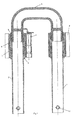
- Fig. 1 shows a Matterrolischutz invention, which is referred to below as a roll bar.
- the roll bar has a Üherroll Ari, which, as from the in Fig. 1 shown sectional view, consists of two iron tubes 1, 2 and a cross bar 3.
- the rollover body is thus in the illustrated embodiment built three elements, but can also be formed of a single element.
- all elements, ie the iron tubes 1, 2 and the cross bar 3 have the same wall thickness.
- the iron tubes and the cross bar 3 may be made of different or the same materials.
- metals such as. As aluminum, magnesium or metal alloys, such as. As a magnesium or aluminum alloy or steel suitable. But it can also be plastics, such as carbon or other Faserverbundwerkstorfe having the required mechanical properties can be used. These material combinations are selectable for all embodiments described below.
- Fig. 1 shown and with reference to the Fig. 2 to 5 explained roll bar is seat-related, that is arranged behind a sitting position of an occupant of a motor vehicle, and protects the occupants from head injuries.
- a hanger 1, 2 and the cross bar 3 it is also possible to arrange on each side of the vehicle, a hanger 1, 2 and the cross bar 3 to be dimensioned so that it extends over the full vehicle width, and the roll bar protects all seated in the vehicle occupants from head injuries.
- the cross bar 3 does not necessarily have to be supported by two stirrup tubes, but may also be connected only to a stirrup tube, whereby the entire rollover body receives a T-shape.
- receptacles 5 For attachment of the rollover body to a vehicle, receptacles 5 are provided which are firmly connected on the one hand to the respective vehicle and in which on the other hand, the iron tubes 1, 2 are displaceable along its longitudinal axis.
- guide bushes 9 may be used, the manufacturing tolerances of the iron tubes 1, 2 and the guides. 5 compensate. As a result, jamming of the ironing tube is successfully prevented.
- a locking mechanism which locks the roll bar after extension and thus prevents retraction of the roll bar.
- This locking mechanism comprises, as in Fig. 1 shown, a conically tapered element 6, which is formed either in the guides 5 itself, or is screwed into this in the form of a sleeve 6 via a thread.
- the sleeve 6 tapers opposite to the approach direction of the roll bar and forms at its lower end a gap with the iron tubes 1, 2 from.
- wedges 7 are used, which abut with their inside to the stirrup tubes 1, 2 and the outside of which has the same pitch as that of the tapered portion 6.
- the pitch of the wedge and the member 6 may also be different, whereby the wedge 7 does not abut the ironing tube, but has the same technical effect which will be described later.
- the outside of the wedges, which abuts against the tapered portion does not necessarily have to have a straight course, as shown in the embodiment, but may be formed both convex and concave.
- the tapered E element 6 forms a concave or convex course corresponding to the outside of the wedges 7.
- a spring element 8, z As a coil spring, is used, which is supported at the end of the guide 5 and the wedges 7 presses in the tapering of the sleeve 6 section. By the spring element 8, the wedges 7 have no play and produce no disturbing noises, such as. B. rattling while driving.
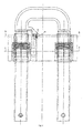
- Fig. 2 the roll bar according to the invention is shown in a phantom drawing, in which the cutting lines of in Fig. 3 and 4 shown sectional views are included.
- Fig. 3 shows the sectional view along the section line AA, from which it can be seen that the ironing tubes 1, 2 and the sleeves 6 have a circular cross-section and between these the wedges 7 are set.
- the cross-section of the wedges 7 is chosen so that they occupy a circular portion of the circular gap, wherein between two adjacent wedges a gap for the correct operation of the locking mechanism is formed.
- Fig. 4 is a sectional view taken along the section line BB Fig. 2 shown, in combination with Fig. 2 shows that the roll-out azimeterde is connected to a portion 31 of the cross bar and a screw 11 with one of the guides 5. This connection is provided so that the roll bar remains stationary while driving and not by blows on the vehicle, eg. B. at bumps, is changed in position.
- the plunger of the pyrotechnic actuator 4 is located on the portion 31 of the cross bar, as in Fig. 1 and 2 shown and practiced Dissolution of the pyrotechnic actuator on the section 31 and consequently on the rollover force, whereby this in the in Fig. 5 shown extended position is offset.
- the clamping connection between the screw 11 and the portion 31 is released. This is made possible by the passage in the section 31 for the screw 11 downwards, as in Fig. 2 shown, is not closed and the pyrotechnic actuator 4 is so strong that it can solve the clamping connection between the screw 11 and the section 3a and catapult the rollover body in its extended position.
- the end position is in Fig. 5 shown.
- the iron tubes 1, 2 are equipped with a stop mechanism, preferably in the form of hollow pins 10. These are inserted into passages in the stirrup tubes 1, 2 and protrude from the peripheral surface of the stirrup tubes 1, 2, thereby preventing the stirrup tubes from being pulled out of the guides 5.
- the stoppage mechanism 10 can be dimensioned so large that the extended roll bar can be used as a towing by attaching a towing hook.
- the tapered element 6 may be formed in either of the above advantageous combinations of either steel or a surface hardened aluminum alloy.
- the surface hardened aluminum alloy may e.g. be prepared by anodizing.
- Fig. 6 a phantom drawing of a roll bar according to a second preferred embodiment of the invention is shown.
- the rollover body is again formed of two ironing tubes 1a, 2a and a transverse bow 3a, wherein the ironing tubes 1a, 2a have a substantially rectangular or oval cross-section, as in the sectional view Fig. 8 recognizable.
- Fig. 7 is a sectional view along the in Fig. 6 shown section line CC, from which it follows that the crossbar 3a has a semicircular cross section and is connected by means of screws 3b with the stirrups 1a, 2a.
- On the transverse bracket 3a is also attached via a screw 3c of acting with the actuator 4 section 3d.
- the section 3d therefore does not necessarily have to be integrated in the crossbar as in the first embodiment.
- the spring element 8a in this case is a leaf spring and not a coil spring.
- the wedges 7a and the tapered element 6a are not bent, thereby simplifying their manufacture, but their function remains the same.
- Fig. 8 is a sectional view taken along the section line DD Fig. 6 It can be seen that both the wedges 7a and the tapered element 6a are plate-like or strip-like and are arranged on the longitudinal side of the substantially rectangular or oval cross section of the ironing tube 1a, 2a. Consequently, the tapered element 6a need not be a sleeve, as in the first embodiment, but may, as mentioned, be plate-like or strip-like.
- Fig. 9 which is an enlarged view of the in Fig. 7 is shown, the tapered element 6a at its upper end at a right angle, whereby it is held in the guide 5a.
- FIG. 9 showing an enlarged view of the locking mechanism is the operation of the locking mechanism the same as that of the first embodiment.
- the wedges 7a are pressed further into the tapered section due to the frictional force between them and the iron tubes and the roll body is determined by clamping action.
- the clamping force is, as in the first embodiment, also reliably transmitted via the wedge surface facing the shackle with the shank tube surface complementary.
- Preferred material combinations of the ironing tubes 1a, 2a, the wedges 7a and the tapered elements 6a are the same as in the first preferred embodiment.
- FIG. 10 the roll bar according to the invention is shown in its basic position.
- This also includes two ironing tubes 1b, 2b and a cross bar 3e.
- the ironing tubes 1b, 2b are formed in this embodiment with a rectangular hollow cross section, wherein the cross bar 3e has recesses for receiving these cross sections.
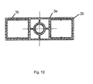
- Fig. 12 shows a sectional view taken along in FIG Fig. 10 shown section line DD, which shows the recesses of the cross bar 3e for receiving the ironing tubes 1b, 2b.
- the cross sections of the ironing tubes 1b, 2b are not limited to rectangular cross sections, but may have any cross-sections, such as those in the first and second embodiments.
- the roll bar of the third preferred embodiment also has a guide 5b, with which the entire roll bar is connected to a vehicle.
- the locking mechanism is not formed on the stirrup tubes 1b, 2b, but an additional driving tube which is locked in the extended state is attached to the cross bar 3b.
- Fig. 11 is a sectional view along the in Fig. 10 shown section line BB shown.
- the additional drive tube 12 is, as shown, on the one hand connected to the cross bar 3b and stirred through the guide 5b.
- a receiving device 13 is formed, which is either bolted to the guide 5b or formed directly on the guide 5b, this receiving device serves to receive an energy storage, for example in the form of a spring 14. So that the spring 14 in the event of a crash force can transmit to the drive tube 12, a bolt 10 b is inserted into the drive tube 12.
- the locking mechanism in this preferred embodiment is the same as in the first or second preferred embodiment and will therefore not be repeated at this point.
- Preferred material combinations of the drive tube and the elements of the locking mechanism are the same as in the first and second preferred embodiment.
- Fig. 12 shown sectional view in conjunction with Fig. 11 , it can be seen that the drive tube 12 is connected to the cross bar 3e via a clamping connection.
- the advantage here is that the recess in the cross bar can also be made as the recess for the iron pipes 1b, 2b in an extrusion process.
- these compounds can be formed by any other adhesion or material or form-locking.
- Fig. 13 shows the entire roll bar of the third preferred embodiment in a sectional view taken along in FIG Fig. 1 shown section line CC.
- the Fig. 14 to 16 show the roll bar of the 10, 11 and 13 in an extended state. This is achieved by triggering the compression spring 14 via a release mechanism, not shown.
- the roll bar can also be extended by a pyrotechnic actuator as in the previous embodiments. Conversely, the extension by means of a spring, which is unlocked by a trigger mechanism, in the other embodiments also possible.
- the Ausileymechanismen can be operated, for example, hydraulically, pyrotechnic or electromagnetic.
- the elements of the rollover body i. H. the iron tubes 1, 2, 1a, 2a, or 1b, 2b and the cross bar 3, 3a, or 3e have any cross-sections and be formed from any material having the required mechanical properties.
- Non-exhaustive examples of this are angular, circular or round cross-sections, or hollow cross-sections, the z. B. were produced by extrusion.
- the elements of the locking mechanism can be configured arbitrarily, wherein the wedges can be arranged on any portion of the outer periphery of the ironing tubes. For proper operation it is sufficient to use only a single wedge in the locking mechanism, but preferably several are to be provided. Furthermore, the wedges and the tapered portion may have any cross section and the spring element may be embodied by different types of springs. In addition, the elements of the locking mechanism of different materials, such. As metal, metal alloys or a required be made of plastic having mechanical properties.
- the locking mechanism is arranged in all embodiments around the ironing tubes around, but it is also possible to provide this on the inside of the hollow cross sections of the ironing tubes.
- the wedges For loosening and re-retraction of the rollover body, the wedges must be pressed with a special tool from below through the gap formed between the ironing tube and the tapered element, against the spring force of the spring element upwards, thereby releasing the locking of the roll bar.
- a roll bar which reliably locks a rollover body in any position only by forming a frictional connection in the locking mechanism can be provided.
Landscapes
- Engineering & Computer Science (AREA)
- Mechanical Engineering (AREA)
- Mutual Connection Of Rods And Tubes (AREA)
- Refuge Islands, Traffic Blockers, Or Guard Fence (AREA)
Applications Claiming Priority (1)
| Application Number | Priority Date | Filing Date | Title |
|---|---|---|---|
| DE102008000661A DE102008000661A1 (de) | 2008-03-13 | 2008-03-13 | Ausfahrbarer Überrollschutz |
Publications (2)
| Publication Number | Publication Date |
|---|---|
| EP2100780A1 true EP2100780A1 (fr) | 2009-09-16 |
| EP2100780B1 EP2100780B1 (fr) | 2011-05-11 |
Family
ID=40568770
Family Applications (1)
| Application Number | Title | Priority Date | Filing Date |
|---|---|---|---|
| EP20090155002 Not-in-force EP2100780B1 (fr) | 2008-03-13 | 2009-03-12 | Système de protection contre les tonneaux avec un arceau extensible |
Country Status (2)
| Country | Link |
|---|---|
| EP (1) | EP2100780B1 (fr) |
| DE (1) | DE102008000661A1 (fr) |
Cited By (2)
| Publication number | Priority date | Publication date | Assignee | Title |
|---|---|---|---|---|
| EP2394866A1 (fr) * | 2010-06-14 | 2011-12-14 | ISE Automotive GmbH | Arceau de sécurité pour un système de protection contre les tonneaux d'un véhicule automobile |
| WO2017058126A1 (fr) * | 2015-09-28 | 2017-04-06 | Tunc Fatih | Support de protection de véhicule |
Families Citing this family (1)
| Publication number | Priority date | Publication date | Assignee | Title |
|---|---|---|---|---|
| DE102013100707A1 (de) * | 2013-01-24 | 2014-07-24 | Benteler Automobiltechnik Gmbh | Überrollschutzsystem |
Citations (6)
| Publication number | Priority date | Publication date | Assignee | Title |
|---|---|---|---|---|
| DE8505101U1 (de) * | 1985-02-22 | 1986-02-27 | Montan-Hydraulik GmbH, 4755 Holzwickede | Kolbenstangen-Klemmvorrichtung |
| DE4342401A1 (de) | 1993-12-13 | 1995-06-14 | Teves Gmbh Alfred | Überrollbügel für Kraftfahrzeuge |
| DE19501522A1 (de) * | 1994-01-29 | 1995-08-03 | Volkswagen Ag | Überrollschutzvorrichtung für eine Cabriolet |
| US5492430A (en) * | 1994-10-14 | 1996-02-20 | Carl A. Hammoms | Telescopic tubes locking device |
| DE19523790A1 (de) | 1995-07-04 | 1997-01-09 | Teves Gmbh Alfred | Ausfahrbarer Überrollbügel |
| DE19750457A1 (de) | 1997-11-14 | 1999-06-02 | Itt Mfg Enterprises Inc | Ausfahrbarer Überrollbügel für Kraftfahrzeuge |
Family Cites Families (1)
| Publication number | Priority date | Publication date | Assignee | Title |
|---|---|---|---|---|
| DE102005028871B4 (de) * | 2005-06-22 | 2007-10-31 | Wilhelm Karmann Gmbh | Überrollschutzsystem für ein Kraftfahrzeug, insbesondere für ein Cabriolet |
-
2008
- 2008-03-13 DE DE102008000661A patent/DE102008000661A1/de not_active Withdrawn
-
2009
- 2009-03-12 EP EP20090155002 patent/EP2100780B1/fr not_active Not-in-force
Patent Citations (6)
| Publication number | Priority date | Publication date | Assignee | Title |
|---|---|---|---|---|
| DE8505101U1 (de) * | 1985-02-22 | 1986-02-27 | Montan-Hydraulik GmbH, 4755 Holzwickede | Kolbenstangen-Klemmvorrichtung |
| DE4342401A1 (de) | 1993-12-13 | 1995-06-14 | Teves Gmbh Alfred | Überrollbügel für Kraftfahrzeuge |
| DE19501522A1 (de) * | 1994-01-29 | 1995-08-03 | Volkswagen Ag | Überrollschutzvorrichtung für eine Cabriolet |
| US5492430A (en) * | 1994-10-14 | 1996-02-20 | Carl A. Hammoms | Telescopic tubes locking device |
| DE19523790A1 (de) | 1995-07-04 | 1997-01-09 | Teves Gmbh Alfred | Ausfahrbarer Überrollbügel |
| DE19750457A1 (de) | 1997-11-14 | 1999-06-02 | Itt Mfg Enterprises Inc | Ausfahrbarer Überrollbügel für Kraftfahrzeuge |
Cited By (3)
| Publication number | Priority date | Publication date | Assignee | Title |
|---|---|---|---|---|
| EP2394866A1 (fr) * | 2010-06-14 | 2011-12-14 | ISE Automotive GmbH | Arceau de sécurité pour un système de protection contre les tonneaux d'un véhicule automobile |
| EP2581274A1 (fr) * | 2010-06-14 | 2013-04-17 | ISE Automotive GmbH | Arceau de sécurité pour un système de protection contre les tonneaux dýun véhicule automobile |
| WO2017058126A1 (fr) * | 2015-09-28 | 2017-04-06 | Tunc Fatih | Support de protection de véhicule |
Also Published As
| Publication number | Publication date |
|---|---|
| EP2100780B1 (fr) | 2011-05-11 |
| DE102008000661A1 (de) | 2009-09-24 |
Similar Documents
| Publication | Publication Date | Title |
|---|---|---|
| EP1802510B1 (fr) | Colonne de direction reglable d'un vehicule | |
| DE69922373T2 (de) | Verschlussvorrichtung und haubenschloss für ein fahrzeug mit einer derartigen verschlussvorrichtung | |
| EP3577011B1 (fr) | Colonne de direction pour un véhicule automobile | |
| DE4342400A1 (de) | Überrollbügeleinrichtung mit Innenführung und Außenführung | |
| DE69715938T2 (de) | Vorrichtung zum Verhindern des Schwenkens des Lenksäulenkörpers eines Kraftfahrzeugs | |
| DE9321498U1 (de) | Überrollbügeleinrichtung mit Innenführung und Außenführung | |
| WO2007101565A1 (fr) | Arrangement de colonne de direction pour véhicules automobiles | |
| DE10022373A1 (de) | Verriegelungs- und Betätigungseinheit für seitliche Auslegerverriegelung | |
| DE10119199B4 (de) | Gurtstraffer | |
| EP2100780B1 (fr) | Système de protection contre les tonneaux avec un arceau extensible | |
| EP1057696B1 (fr) | Dispositif à arceau de sécurité pour véhicules | |
| DE102005029253A1 (de) | Überrollschutzsystem für ein Kraftfahrzeug | |
| DE4112405A1 (de) | Sattelkupplungseinrichtung stichwort: einhandbetaetigungsgriff | |
| DE10103247C1 (de) | Überrollschutzsystem für Kraftfahrzeuge | |
| WO2005028282A1 (fr) | Ensemble colonne de direction | |
| WO2005028281A1 (fr) | Ensemble colonne de direction comprenant une colonne de direction a inclinaison et longueur modifiables | |
| WO2009059655A1 (fr) | Ensemble colonne de direction pour véhicules automobiles | |
| EP1538287B1 (fr) | Poignée extérieure de porte | |
| DE10143939B4 (de) | Schließeinrichtung für ein Kraftfahrzeug | |
| EP1539543B1 (fr) | Systeme de protection en cas de tonneaux pour vehicules automobiles | |
| DE102004011089A1 (de) | Kraftfahrzeugsitz | |
| DE102016210875A1 (de) | Vorrichtung zur Freigabe einer Bewegung einer Komponente sowie Sitz mit einer solchen Vorrichtung | |
| EP2216211A1 (fr) | Système de protection contre le retournement | |
| AT527944B1 (de) | Anprallvorrichtung | |
| DE10317448A1 (de) | Kupplungseinrichtung an Doppelschließzylinder |
Legal Events
| Date | Code | Title | Description |
|---|---|---|---|
| PUAI | Public reference made under article 153(3) epc to a published international application that has entered the european phase |
Free format text: ORIGINAL CODE: 0009012 |
|
| AK | Designated contracting states |
Kind code of ref document: A1 Designated state(s): AT BE BG CH CY CZ DE DK EE ES FI FR GB GR HR HU IE IS IT LI LT LU LV MC MK MT NL NO PL PT RO SE SI SK TR |
|
| AX | Request for extension of the european patent |
Extension state: AL BA RS |
|
| 17P | Request for examination filed |
Effective date: 20091130 |
|
| 17Q | First examination report despatched |
Effective date: 20100108 |
|
| AKX | Designation fees paid |
Designated state(s): DE FR GB IT |
|
| GRAP | Despatch of communication of intention to grant a patent |
Free format text: ORIGINAL CODE: EPIDOSNIGR1 |
|
| GRAS | Grant fee paid |
Free format text: ORIGINAL CODE: EPIDOSNIGR3 |
|
| GRAA | (expected) grant |
Free format text: ORIGINAL CODE: 0009210 |
|
| AK | Designated contracting states |
Kind code of ref document: B1 Designated state(s): DE FR GB IT |
|
| REG | Reference to a national code |
Ref country code: GB Ref legal event code: FG4D Free format text: NOT ENGLISH |
|
| REG | Reference to a national code |
Ref country code: DE Ref legal event code: R096 Ref document number: 502009000641 Country of ref document: DE Effective date: 20110622 |
|
| PLBE | No opposition filed within time limit |
Free format text: ORIGINAL CODE: 0009261 |
|
| STAA | Information on the status of an ep patent application or granted ep patent |
Free format text: STATUS: NO OPPOSITION FILED WITHIN TIME LIMIT |
|
| 26N | No opposition filed |
Effective date: 20120214 |
|
| REG | Reference to a national code |
Ref country code: DE Ref legal event code: R097 Ref document number: 502009000641 Country of ref document: DE Effective date: 20120214 |
|
| REG | Reference to a national code |
Ref country code: DE Ref legal event code: R082 Ref document number: 502009000641 Country of ref document: DE Representative=s name: KOTITSCHKE & HEURUNG PARTNERSCHAFT MBB PATENT-, DE Ref country code: DE Ref legal event code: R082 Ref document number: 502009000641 Country of ref document: DE Representative=s name: KOTITSCHKE & HEURUNG PARTNERSCHAFT MBB, DE Ref country code: DE Ref legal event code: R082 Ref document number: 502009000641 Country of ref document: DE Representative=s name: DR. RALF KOTITSCHKE, DE |
|
| PGFP | Annual fee paid to national office [announced via postgrant information from national office to epo] |
Ref country code: DE Payment date: 20140331 Year of fee payment: 6 |
|
| PGFP | Annual fee paid to national office [announced via postgrant information from national office to epo] |
Ref country code: IT Payment date: 20140319 Year of fee payment: 6 |
|
| PGFP | Annual fee paid to national office [announced via postgrant information from national office to epo] |
Ref country code: GB Payment date: 20140321 Year of fee payment: 6 |
|
| PGFP | Annual fee paid to national office [announced via postgrant information from national office to epo] |
Ref country code: FR Payment date: 20140327 Year of fee payment: 6 |
|
| REG | Reference to a national code |
Ref country code: DE Ref legal event code: R119 Ref document number: 502009000641 Country of ref document: DE |
|
| GBPC | Gb: european patent ceased through non-payment of renewal fee |
Effective date: 20150312 |
|
| PG25 | Lapsed in a contracting state [announced via postgrant information from national office to epo] |
Ref country code: IT Free format text: LAPSE BECAUSE OF NON-PAYMENT OF DUE FEES Effective date: 20150312 |
|
| REG | Reference to a national code |
Ref country code: FR Ref legal event code: ST Effective date: 20151130 |
|
| PG25 | Lapsed in a contracting state [announced via postgrant information from national office to epo] |
Ref country code: GB Free format text: LAPSE BECAUSE OF NON-PAYMENT OF DUE FEES Effective date: 20150312 Ref country code: DE Free format text: LAPSE BECAUSE OF NON-PAYMENT OF DUE FEES Effective date: 20151001 |
|
| PG25 | Lapsed in a contracting state [announced via postgrant information from national office to epo] |
Ref country code: FR Free format text: LAPSE BECAUSE OF NON-PAYMENT OF DUE FEES Effective date: 20150331 |