EP2100976B1 - Procédé de formage local de zones d'une plaque de tôle d'un joint plat fabriquée à partir d'une tôle d'acier à ressort. - Google Patents
Procédé de formage local de zones d'une plaque de tôle d'un joint plat fabriquée à partir d'une tôle d'acier à ressort. Download PDFInfo
- Publication number
- EP2100976B1 EP2100976B1 EP09003515A EP09003515A EP2100976B1 EP 2100976 B1 EP2100976 B1 EP 2100976B1 EP 09003515 A EP09003515 A EP 09003515A EP 09003515 A EP09003515 A EP 09003515A EP 2100976 B1 EP2100976 B1 EP 2100976B1
- Authority
- EP
- European Patent Office
- Prior art keywords
- sheet metal
- metal layer
- area
- accordance
- inductor
- Prior art date
- Legal status (The legal status is an assumption and is not a legal conclusion. Google has not performed a legal analysis and makes no representation as to the accuracy of the status listed.)
- Not-in-force
Links
- 239000002184 metal Substances 0.000 title claims description 240
- 229910052751 metal Inorganic materials 0.000 title claims description 240
- 238000000034 method Methods 0.000 title claims description 47
- 229910000639 Spring steel Inorganic materials 0.000 title claims description 29
- 238000010438 heat treatment Methods 0.000 claims description 51
- 230000006698 induction Effects 0.000 claims description 36
- 238000007789 sealing Methods 0.000 claims description 25
- 230000005672 electromagnetic field Effects 0.000 claims description 20
- 230000001939 inductive effect Effects 0.000 claims description 18
- 230000005291 magnetic effect Effects 0.000 claims description 17
- 229910000831 Steel Inorganic materials 0.000 claims description 9
- 239000010959 steel Substances 0.000 claims description 9
- 239000004020 conductor Substances 0.000 claims description 6
- 230000008569 process Effects 0.000 claims description 5
- 238000001953 recrystallisation Methods 0.000 claims description 3
- 239000007858 starting material Substances 0.000 claims description 3
- 230000000694 effects Effects 0.000 claims description 2
- 230000009975 flexible effect Effects 0.000 claims 1
- 230000009466 transformation Effects 0.000 claims 1
- 239000010410 layer Substances 0.000 description 210
- 239000011324 bead Substances 0.000 description 31
- 238000002485 combustion reaction Methods 0.000 description 15
- 239000000463 material Substances 0.000 description 10
- 230000008859 change Effects 0.000 description 9
- 238000005452 bending Methods 0.000 description 7
- 238000004519 manufacturing process Methods 0.000 description 7
- 239000003570 air Substances 0.000 description 6
- 239000012530 fluid Substances 0.000 description 5
- 230000035699 permeability Effects 0.000 description 5
- 238000004080 punching Methods 0.000 description 5
- 125000006850 spacer group Chemical group 0.000 description 5
- 238000002788 crimping Methods 0.000 description 4
- 238000004049 embossing Methods 0.000 description 4
- 238000010894 electron beam technology Methods 0.000 description 3
- 239000004033 plastic Substances 0.000 description 3
- 230000009467 reduction Effects 0.000 description 3
- XEEYBQQBJWHFJM-UHFFFAOYSA-N Iron Chemical compound [Fe] XEEYBQQBJWHFJM-UHFFFAOYSA-N 0.000 description 2
- 230000008901 benefit Effects 0.000 description 2
- 239000000919 ceramic Substances 0.000 description 2
- 230000006835 compression Effects 0.000 description 2
- 238000007906 compression Methods 0.000 description 2
- 239000012141 concentrate Substances 0.000 description 2
- 238000001816 cooling Methods 0.000 description 2
- 230000006378 damage Effects 0.000 description 2
- 230000005294 ferromagnetic effect Effects 0.000 description 2
- 238000009434 installation Methods 0.000 description 2
- 239000002245 particle Substances 0.000 description 2
- 239000002356 single layer Substances 0.000 description 2
- 229910000975 Carbon steel Inorganic materials 0.000 description 1
- 239000012080 ambient air Substances 0.000 description 1
- 239000010962 carbon steel Substances 0.000 description 1
- 238000010924 continuous production Methods 0.000 description 1
- 238000005336 cracking Methods 0.000 description 1
- 230000006866 deterioration Effects 0.000 description 1
- 238000007598 dipping method Methods 0.000 description 1
- 238000009826 distribution Methods 0.000 description 1
- 230000002349 favourable effect Effects 0.000 description 1
- 230000001771 impaired effect Effects 0.000 description 1
- 239000011810 insulating material Substances 0.000 description 1
- 229910052742 iron Inorganic materials 0.000 description 1
- 230000002427 irreversible effect Effects 0.000 description 1
- 229910000734 martensite Inorganic materials 0.000 description 1
- 230000035515 penetration Effects 0.000 description 1
- 230000000284 resting effect Effects 0.000 description 1
- 238000010583 slow cooling Methods 0.000 description 1
- 229920001169 thermoplastic Polymers 0.000 description 1
- 239000004416 thermosoftening plastic Substances 0.000 description 1
- 230000007704 transition Effects 0.000 description 1
- 238000003466 welding Methods 0.000 description 1
- 230000037303 wrinkles Effects 0.000 description 1
Images




Classifications
-
- B—PERFORMING OPERATIONS; TRANSPORTING
- B21—MECHANICAL METAL-WORKING WITHOUT ESSENTIALLY REMOVING MATERIAL; PUNCHING METAL
- B21D—WORKING OR PROCESSING OF SHEET METAL OR METAL TUBES, RODS OR PROFILES WITHOUT ESSENTIALLY REMOVING MATERIAL; PUNCHING METAL
- B21D53/00—Making other particular articles
- B21D53/16—Making other particular articles rings, e.g. barrel hoops
- B21D53/20—Making other particular articles rings, e.g. barrel hoops washers, e.g. for sealing
-
- C—CHEMISTRY; METALLURGY
- C21—METALLURGY OF IRON
- C21D—MODIFYING THE PHYSICAL STRUCTURE OF FERROUS METALS; GENERAL DEVICES FOR HEAT TREATMENT OF FERROUS OR NON-FERROUS METALS OR ALLOYS; MAKING METAL MALLEABLE, e.g. BY DECARBURISATION OR TEMPERING
- C21D1/00—General methods or devices for heat treatment, e.g. annealing, hardening, quenching or tempering
- C21D1/04—General methods or devices for heat treatment, e.g. annealing, hardening, quenching or tempering with simultaneous application of supersonic waves, magnetic or electric fields
-
- C—CHEMISTRY; METALLURGY
- C21—METALLURGY OF IRON
- C21D—MODIFYING THE PHYSICAL STRUCTURE OF FERROUS METALS; GENERAL DEVICES FOR HEAT TREATMENT OF FERROUS OR NON-FERROUS METALS OR ALLOYS; MAKING METAL MALLEABLE, e.g. BY DECARBURISATION OR TEMPERING
- C21D1/00—General methods or devices for heat treatment, e.g. annealing, hardening, quenching or tempering
- C21D1/34—Methods of heating
- C21D1/42—Induction heating
-
- C—CHEMISTRY; METALLURGY
- C21—METALLURGY OF IRON
- C21D—MODIFYING THE PHYSICAL STRUCTURE OF FERROUS METALS; GENERAL DEVICES FOR HEAT TREATMENT OF FERROUS OR NON-FERROUS METALS OR ALLOYS; MAKING METAL MALLEABLE, e.g. BY DECARBURISATION OR TEMPERING
- C21D7/00—Modifying the physical properties of iron or steel by deformation
- C21D7/13—Modifying the physical properties of iron or steel by deformation by hot working
-
- C—CHEMISTRY; METALLURGY
- C21—METALLURGY OF IRON
- C21D—MODIFYING THE PHYSICAL STRUCTURE OF FERROUS METALS; GENERAL DEVICES FOR HEAT TREATMENT OF FERROUS OR NON-FERROUS METALS OR ALLOYS; MAKING METAL MALLEABLE, e.g. BY DECARBURISATION OR TEMPERING
- C21D9/00—Heat treatment, e.g. annealing, hardening, quenching or tempering, adapted for particular articles; Furnaces therefor
- C21D9/02—Heat treatment, e.g. annealing, hardening, quenching or tempering, adapted for particular articles; Furnaces therefor for springs
-
- F—MECHANICAL ENGINEERING; LIGHTING; HEATING; WEAPONS; BLASTING
- F16—ENGINEERING ELEMENTS AND UNITS; GENERAL MEASURES FOR PRODUCING AND MAINTAINING EFFECTIVE FUNCTIONING OF MACHINES OR INSTALLATIONS; THERMAL INSULATION IN GENERAL
- F16J—PISTONS; CYLINDERS; SEALINGS
- F16J15/00—Sealings
- F16J15/02—Sealings between relatively-stationary surfaces
- F16J15/06—Sealings between relatively-stationary surfaces with solid packing compressed between sealing surfaces
- F16J15/08—Sealings between relatively-stationary surfaces with solid packing compressed between sealing surfaces with exclusively metal packing
- F16J15/0818—Flat gaskets
-
- C—CHEMISTRY; METALLURGY
- C21—METALLURGY OF IRON
- C21D—MODIFYING THE PHYSICAL STRUCTURE OF FERROUS METALS; GENERAL DEVICES FOR HEAT TREATMENT OF FERROUS OR NON-FERROUS METALS OR ALLOYS; MAKING METAL MALLEABLE, e.g. BY DECARBURISATION OR TEMPERING
- C21D1/00—General methods or devices for heat treatment, e.g. annealing, hardening, quenching or tempering
- C21D1/62—Quenching devices
- C21D1/673—Quenching devices for die quenching
-
- C—CHEMISTRY; METALLURGY
- C21—METALLURGY OF IRON
- C21D—MODIFYING THE PHYSICAL STRUCTURE OF FERROUS METALS; GENERAL DEVICES FOR HEAT TREATMENT OF FERROUS OR NON-FERROUS METALS OR ALLOYS; MAKING METAL MALLEABLE, e.g. BY DECARBURISATION OR TEMPERING
- C21D2211/00—Microstructure comprising significant phases
- C21D2211/001—Austenite
-
- C—CHEMISTRY; METALLURGY
- C21—METALLURGY OF IRON
- C21D—MODIFYING THE PHYSICAL STRUCTURE OF FERROUS METALS; GENERAL DEVICES FOR HEAT TREATMENT OF FERROUS OR NON-FERROUS METALS OR ALLOYS; MAKING METAL MALLEABLE, e.g. BY DECARBURISATION OR TEMPERING
- C21D2221/00—Treating localised areas of an article
-
- Y—GENERAL TAGGING OF NEW TECHNOLOGICAL DEVELOPMENTS; GENERAL TAGGING OF CROSS-SECTIONAL TECHNOLOGIES SPANNING OVER SEVERAL SECTIONS OF THE IPC; TECHNICAL SUBJECTS COVERED BY FORMER USPC CROSS-REFERENCE ART COLLECTIONS [XRACs] AND DIGESTS
- Y02—TECHNOLOGIES OR APPLICATIONS FOR MITIGATION OR ADAPTATION AGAINST CLIMATE CHANGE
- Y02P—CLIMATE CHANGE MITIGATION TECHNOLOGIES IN THE PRODUCTION OR PROCESSING OF GOODS
- Y02P10/00—Technologies related to metal processing
- Y02P10/25—Process efficiency
-
- Y—GENERAL TAGGING OF NEW TECHNOLOGICAL DEVELOPMENTS; GENERAL TAGGING OF CROSS-SECTIONAL TECHNOLOGIES SPANNING OVER SEVERAL SECTIONS OF THE IPC; TECHNICAL SUBJECTS COVERED BY FORMER USPC CROSS-REFERENCE ART COLLECTIONS [XRACs] AND DIGESTS
- Y10—TECHNICAL SUBJECTS COVERED BY FORMER USPC
- Y10T—TECHNICAL SUBJECTS COVERED BY FORMER US CLASSIFICATION
- Y10T29/00—Metal working
- Y10T29/49—Method of mechanical manufacture
- Y10T29/49805—Shaping by direct application of fluent pressure
Definitions
- Metallic flat gaskets in particular gaskets used in conjunction with internal combustion engines, such as cylinder head gaskets, exhaust manifold gaskets and the like, typically have at least one sheet metal layer made of a spring steel sheet which not only has openings and holes for the passage of mounting screws serving as fluid passage openings also elastic sealing beads in the form of so-called full corrugations and / or half beads, these beads associated deformation limiter (called stopper) and optionally in addition to such stoppers further supporting elements, which are not associated with a bead and serve the purpose when clamping the gasket between machine component sealing surfaces and to absorb compressive forces acting on the flat gasket during operation in order to at least minimize distortion of the machine components and in particular of the machine component sealing surfaces.
- stopper deformation limiter
- the total thickness of the sheet metal layer is greater than in areas adjacent to the supporting elements of the sheet metal layer, and that the height of a stopper (overhang of the stopper on adjacent to these areas of the sheet metal layer) something must be smaller than the height of the caulking, so this in engine operation "working", that is, that the height of the bead can change reversibly before the stopper is pressed and then prevents further flattening of the bead, so that it can not be destroyed in the engine operation by the dynamic compressive stress.
- the stoppers and other support members usually have the following shapes, if it is to be omitted to use as a stopper or support a manufactured as a separate sheet metal stamped element which is fixed on the sheet metal layer, for example by spot welding: An edge region the sheet metal layer (be it on an outer or an inner edge of the sheet metal layer lying edge) is bent by approximately 180 ° and folded back to the sheet metal layer, or is such an edge area thickened by a plastic deformation of the sheet, for example by a stamping process or by Dipping the sheet metal from the edge of the sheet metal layer.
- the EP-A-0 863 335 is a particular single-layer metallic gasket, such as a cylinder head gasket is described, in which a sheet metal layer made of a spring steel sheet around a sealed opening around a sealing element is formed, which has the shape of a bead or a flanged (folded) edge portion of the sheet metal layer.
- the sheet metal layer in the later forming the sealing member area to achieve a structural change and concomitant softening of the spring steel sheet heat treated, and after the production of the support this is thermally treated to give it the desired hardness.
- the heat treatment to reduce the hardness of the spring steel sheet are in the EP-A-0 863 335 mentions inductive heating and heating by means of a laser, microwaves or electron beams.
- a sheet metal layer of a flat gasket is made only from a relatively expensive spring steel sheet, if the sheet metal layer has elements which have functionally necessary spring elastic properties.
- an element having elastic properties is located in the vicinity of a support member formed by forming the sheet metal layer, a reduction in the hardness of the sheet layer by heat treatment before forming leads to deterioration of the elastic properties, for example, in the vicinity of by forming Sheet metal layer to be produced supporting element located sealing bead.
- the hardness of the spring steel sheet is reduced in this range by local inductive heating.
- the edge region to be folded over to form the stopper is first bent only by about 90 °, so that it forms a raised collar, onto which an induction coil enclosing this collar is slid so that it is adjacent to the collar root, in order to induce those induced in the sheet metal Concentrate heat on the area of the collar root and thus on the sheet metal area that is to be further shaped.
- the invention has for its object to sufficiently heat a region of the sheet metal layer to be formed for producing a support element in a simple and therefore cost-effective manner for the purpose of reducing its hardness so that the energy input required for the heating is concentrated on a narrowly limited area of the sheet metal layer, This area adjacent sheet metal areas are not softened and in the course of heating, the emergence of dislocations of the sheet is at least largely avoided.
- inductor an electrical conductor through which an electrical alternating current passes
- heat energy with a power of several tens of thousands of W / cm 2 can be introduced into a spring steel sheet;
- the electromagnetic alternating field generated by the inductor surrounds the inductor (in cross-section) annularly without additional measures, it requires a narrow boundary of the inductively heated portion of the sheet metal layer of a magnetic field concentrator, in which it is a jacket enclosing the inductor a material of relatively high permeability, which at the point at which the alternating electromagnetic field from the unit consisting of inductor and magnetic field concentrator exit and act on the region to be softened sheet metal layer, an opening which may also be a window-like opening closed by a material of relatively low permeability.
- Such units consisting of inductor and magnetic field concentrator are known from the prior art, for example from the "Material Brochure Ferrotron® and Fluxtrol®” from POLYTRON Kunststofftechnik GmbH & Co. KG, D-51469 Bergisch-Gladbach.
- Such a magnetic field concentrator is preferably made of a material which has both ferromagnetic and dielectric properties and consists essentially of soft iron particles which are evenly distributed embedded in a thermoplastic high-performance plastic.
- a magnetic field concentrator as such also results from the US 2007/0194010 A1 , which discloses a device for the field-wise inductive heating of a sheet having on both sides of the sheet induction coils and magnetic field concentrators and serves the purpose of producing a desired temperature profile in the sheet.
- the inventive method is preferably used for spring steels with a yield strength (R e ) of at least 1000 N / mm 2 as the starting material, as otherwise areas of such spring steel plates can be transformed only very problematic to so-called stoppers or other support elements of a flat gasket layer.
- a spring steel sheet made of an austenitic spring steel is particularly suitable since, for example, a martensitic carbon steel must be rapidly cooled after heating.
- the method according to the invention allows heating of the area of the sheet metal layer to be formed to 700 ° C. or more within a very short time, and preferably in the method of the invention, the area to be formed is heated to a temperature of about 700 ° C to about 900 ° C.
- the area of the spring steel sheet metal layer to be reshaped is not heated above a temperature of approximately 900 ° C., recrystallization still does not occur in the steel - if recrystallization were to occur during the heating of the sheet metal layer in this form irreversible waves, which is to be avoided in a sheet metal layer of a flat gasket.
- the invention thus relates in particular to a method for producing a sheet-metal layer which has a sheet-metal layer region provided with a deformation in the immediate vicinity of the support element, which has spring-elastic properties even without a thermal post-treatment, wherein the method is characterized in that the inductive heating of the with the Supporting to be provided area of the sheet metal layer after exposure time, concentration and energy of the electromagnetic alternating field is chosen such that the steel in the provided with the deformation or provided area of the sheet metal layer undergoes at least no appreciable structural change and thus strength change.
- the invention relates to such a method in which the deformation is a resilient sealing bead, for which the support element forms a deformation limiter (stopper).
- an exposure time of the electromagnetic alternating field of a few milliseconds to at most approximately 1 second is sufficient for most spring steel sheet metal layers of flat gaskets because of their small sheet thickness, on each part of the area of the sheet metal layer to be reshaped.
- this frequency should not be too high, but it may also should not be too low, so that the electromagnetic alternating field in the sheet metal layer sufficiently strong, responsible for the heating of the sheet eddy currents generated. Therefore, it is recommended for the inventive method to use an alternating electromagnetic field having a frequency of a few hundred kHz to about 1 MHz, in particular a frequency in the order of 200 to 500 kHz.
- the area of the sheet metal layer to be reshaped can already be formed in the course of heating, in particular in such a way that the at least one inductor together with the the magnetic field concentration device assigned to the latter is also designed as a forming tool or combined with it to form a structural unit.
- a non-inventive device for carrying out the method according to the invention which has at least one connectable to an AC power source electrical conductor as an inductor for inductive heating of the reshaped portion of the sheet metal layer and is characterized by the inductor partially enclosing magnetic field Concentration device or magnetic field shielding device, which forms an induction unit together with the inductor and has a zuzutormenden the region of the sheet metal layer zulidende opening in the region of the magnetic field concentration device for the alternating electromagnetic field is permeable.
- the shape of the induction unit is adapted to the shape of the region of the sheet metal layer to be formed
- the induction unit has the shape of a ring.
- the device not according to the invention can also be designed such that the induction unit and the sheet metal layer are movable relative to one another during the heating of the latter in such a way that the induction zone can be overrun with the area of the sheet metal layer to be reshaped, such that adjacent to one another with such an induction unit Sections of the reshaped portion of the sheet metal layer are heated one after the other.
- the induction unit is designed as a forming tool or combined with a forming tool and combined to form a unit, so that the forming process in the course of heating the area of the sheet metal layer to be formed or directly after heating can be carried out; It is particularly favorable if the sheet-metal layer is kept stationary for heating and forming and the mentioned structural unit is moved over the area to be reshaped or the areas of the sheet-metal layer to be reshaped so as to be able to continuously carry out the heating and forming in one step.
- the device has at least one holding-down device for the sheet-metal layer.
- the device may have a spacer plate of low permeability between the induction unit and the sheet-metal layer.
- FIG. 1 shown part of a sheet metal layer of a gasket is typical for a single or multi-layer metallic cylinder head gasket, and the FIG. 1 shows an axis 10 of a combustion chamber opening 12, which has been punched out of a sheet metal layer 14 of the cylinder head gasket.
- the sheet metal layer 14 has a combustion chamber opening 12 enclosing annular and designed as a so-called full bead sealing bead 16, which, since the sheet metal layer 14 was made of spring steel, has resilient properties and flatten reversibly, that is in their Reduce height when the cylinder head gasket between a cylinder head and an engine block is clamped, the sealing bead 16 can adapt due to their elastic properties in height of the periodically fluctuating in engine operation width or width of the so-called sealing gap, which are sealed by the cylinder head gasket should and is defined by non-illustrated sealing surfaces of the cylinder head and the engine block.
- the sealing bead 16 is associated with a designated as a whole with 18 stopper, which also surrounds the combustion chamber opening 12 annularly and by forming, by embossing, the sheet metal layer 14 was generated.
- 18 stopper also surrounds the combustion chamber opening 12 annularly and by forming, by embossing, the sheet metal layer 14 was generated.
- the stopper 18 has elevations 18a and corresponding recesses 18b, which may surround the combustion chamber opening 12 annularly, but may also be designed so that in a plan view of the sheet metal layer 14, the elevations 18a, for example, a checkerboard-like pattern of discrete, knob-like elevations 18a and depressions 18b form a corresponding pattern of discrete recesses 18b in a bottom view of sheet metal layer 14.
- the combustion chamber opening 12 enclosing portion of the sheet metal layer 14 is formed in the after forming the stopper 18, heat treated according to the invention, in such a way that by the local, short-term heating of the sheet-metal layer 14, the elastic properties of the sealing bead 16 were not impaired.
- a sheet metal layer 14 ' also has a sealing bead 16' and a stopper 18 ', both of which surround a combustion chamber opening 12' annular and concentric with the axis 10 'of the combustion chamber opening.
- the stopper 18 ' has been produced by crimping an edge region of the sheet metal layer 14' running around the axis 10 'of the combustion chamber opening, that is, in this edge region the sheet metal layer 14' has been folded over on itself, after an annular region of the sheet-metal layer 14 ', in which, after the stopper 18' has been produced, the bending radius of the sheet-metal layer or stopper 18 'is heat-treated according to the invention in order to be able to fold the sheet-metal layer 14' free of cracks.
- the stoppers 18 and 18 'at unloaded, that is not yet built flat gasket has a slightly lower height than the sealing bead 16 or 16', so that they slightly elastic during installation of the gasket and in operation can flatten before the associated stopper 18 or 18 'comes to fruition, that is, on the sheet metal layer 14 and 14' around the combustion chamber opening 12 and 12 'around acting pressure forces and prevents further flattening of the sealing bead.
- a stopper In order for a stopper to act as a deformation limiter, it must be so hard that it catches under the impact of the Installation of the gasket and compressive forces occurring during operation at least not significantly deformed (neither elastic, nor plastic), that is, at least substantially retains its original height.
- a cylinder head gasket it may be necessary to provide support elements that are the same or similar to the stopper 18 or the stopper 18 'also at locations other than around a combustion chamber opening or other fluid opening, for example at the periphery the gasket of a cylinder head gasket, in particular on the narrow sides of a cylinder head gasket intended for a multi-cylinder engine, namely for the purpose of minimizing distortion in the engine components cylinder head and engine block, in particular the cylinder head - such component distortions are caused in a multi-cylinder engine, that due to Distribution of the cylinder head bolts over the engine components, the compression forces generated by the cylinder head bolts and acting on the cylinder head gasket in the areas of the two longitudinal ends of a cylinder head gasket for a multi-cylinder engine are higher than in other areas; but locally different component stiffnesses of the engine block and the cylinder head can also lead to such locally different pressure forces, so that by such differences in the compressive forces otherwise induced component distortion should be minimized by provided on the
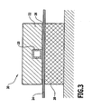
- FIG. 3 shown embodiment of a device not according to the invention has an inductor 20 shown only schematically, which, should an annular support element are produced by forming a spring steel sheet metal layer, adapted to the shape of the sheet metal layer area to be formed and in a view according to FIG. 3 from above also an annular Has shape.
- the inductor 20 can be, for example, an annular metallic (electrical) conductor, but also an annular coil for generating an electromagnetic alternating field.
- the inductor 20 is inserted in a magnetic field concentrator 22, which consists of a material of high permeability, in particular of a material having ferromagnetic properties.
- the concentrator 22 encloses the inductor 20 at the top and on both sides, but not below (in accordance with FIG FIG. 3 ), so that the alternating electromagnetic field generated by the inductor 20 act on a sheet metal layer 24 and can generate in this local heating of the sheet metal layer serving eddy currents.
- the electromagnetic alternating field acting on the sheet-metal layer 24 is concentrated and restricted to that region of the sheet-metal layer 24 which under (according to FIG FIG. 3 ) the inductor 20 is located.
- an air gap 26 is provided between the inductor 20 and the sheet-metal layer 24 so that the sheet-metal layer does not come into contact with the inductor 20.
- a table-like support 28 is provided for the sheet-metal layer 24, which is advantageously a unit made of a material such as ceramic, which is the electromagnetic generated by the inductor 20 and concentrator 22 induction unit generated Alternating field is not affected and also has the lowest possible thermal conductivity, so that the area to be heated by the induction unit 30 of the sheet-metal layer 24 is not cooled by the support 28.
- FIG. 4 illustrated embodiment of the device not according to the invention differs from that according to FIG. 3 only in that it has a second inductor, which is why in FIG. 4 the same reference numerals as in FIG. 3 are used, one sees from the reference numeral for the second inductor off.
- This second inductor 20 ' is opposite to the other inductor 20 and is embedded in the run as a ceramic plate pad 28.
- Corresponding to the air gap 26 of the embodiment according to FIG. 3 is in the embodiment according to FIG.
- FIG. 4 also indicates that it may be useful to maintain a distance between the sheet metal layer 24 and an inductor to provide the device not according to the invention with a spacer between the inductor and the sheet metal layer 24, this spacer must of course consist of a material, which on the one hand electrically non-conductive and on the other hand, is permeable to the alternating electromagnetic field, that is, has a low permeability.
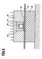
- FIG. 5 shown further embodiment of the device not according to the invention is largely with the in FIG. 3 identical embodiment, which is why in FIG. 5 , as far as possible, the same reference numerals as in FIG. 3 were used and below only those features of the FIG. 5 illustrated embodiment, by which the two embodiments differ.
- the embodiment according to FIG. 5 has between the inductor 20 and the smaller than in the embodiment according to FIG. 3 designed concentrator 22 serving as a spacer intermediate plate 34 of an electrically insulating, but permeable to the electromagnetic alternating field material, which ensures that the sheet metal layer 24, especially in the course of their heating can not come into contact with the inductor 20.
- the inductor 20 and the concentrator 22 are inserted into a stamp-like hold-down device 36, for example, which, as indicated by arrows, according to FIG. 5 can be pressed down against the resting on the support 28 sheet metal layer 24 (by means not shown) and serving as a hold-down surface underside with the bottom of the intermediate plate 34 is flush.
- Analogous to the embodiment according to FIG. 5 can also be the embodiment according to FIG. 4 be provided with intermediate plates, which fill the air gaps 26 and 26 'at least in the region of the two inductors 20 and 20' and between which the sheet-metal layer 24 can be arranged.
- the blank holder 36 at least largely avoid that the sheet metal layer 24 forms when heating by the induction unit 30 bumps or folds - this is prevented by the sheet metal layer 24 is pressed at least next to the inductor 20 down against the support 28 and between them Pad and the intermediate plate 34 is clamped.
- the sheet metal layer is to be formed in the region provided by inductive heating with a lower hardness, it may be advantageous to provide the region to be heated with a deformation already before the inductive heating, which on the one hand causes that taking place in the course of inductive heating Thermal expansions of the sheet metal layer lead to a deformation of the sheet metal layer in a given direction, and on the other can serve to facilitate the subsequent to the inductive heating forming process. This should be based on the FIG. 6 be explained in more detail.
- FIG. 6 shows an embodiment of the non-inventive device, which compared to the embodiment according to FIG. 5 has been slightly modified, and only insofar as the intermediate plate 34 of the embodiment according to FIG. 5 omitted and the inductor 20 is adapted in its shape, namely on its underside to the geometry of a deformation of the sheet metal layer 24, which was formed before the inductive heating of the sheet metal layer in the latter.
- this deformation of the sheet metal layer 24 has the shape of a bead 40, and the underside of the inductor 20 is designed accordingly.
- the bead 40 now also facilitates an optionally carried out beading or crimping according to FIG. 6 right end portion of the sheet metal layer 24, when the beading is made so that the bending radius of the flanged portion (see FIG. 2 ) is located where the crest or the crest of the bead 40 was before flanging.
- FIG. 7A shows a device similar to that according to FIG. 3 However, wherein the induction unit 30 as in the embodiment according to FIG. 5 is inserted into a hold-down 36. In place of in FIG. 7A shown air gap, an intermediate plate according to the intermediate plate 34 of the embodiment according to FIG. 5 to step.
- an area of the sheet metal layer 24 adjacent to the inductively heated region of FIG Sheet metal layer provided by punching with an edge or an edge of predetermined geometry, in a punching device, which in FIG. 7B has been shown schematically.
- This punching device has a die 42 partially shown, a part shown and designed as a punch 44 male and a hold-down 46 partially shown for clamping the sheet-metal layer 24 between this and the die 42nd
- FIG. 7B After punching the according to FIG. 7B formed right edge region of the sheet-metal layer 24, for example by crimping by means of a tool, not shown (see the FIG. 2 ), so that the sheet metal layer 24 in FIG. 7C receives shown shape.
- the stopper is to be provided with a profile, for example with a length of the stopper (perpendicular to the plane of the FIG. 7C ) varying height or thickness, it is advisable to heat the sheet-metal layer 24 in the region of the stopper 18 'inductively again to facilitate the required for the generation of the height profile forming (embossing).
- FIG. 7C schematically shown device with a support 28 for the sheet-metal layer 24, an inductor 20, a concentrator 22 and a hold-down 36th
- FIG. 7D Finally, schematically shows a press or embossing device with two punches 50 and 52, with which the desired profile can be embossed in the stopper 18 '.
- a device not according to the invention is not used to inductively heat a region of a spring steel sheet metal layer to be formed in order to be able to provide a spring steel sheet metal layer with a support element, for example a stopper, but that the device not according to the invention is designed and used so that it can change (reduce) in its hardness a previously prepared support in its hardness.
- the magnetic field concentrator of a device not according to the invention optionally contains electrically conductive particles
- Such a variant shows the FIG. 8 according to which the inductor 20 is enclosed by an electrically insulating layer 54 in the manner of a jacket.
- FIG. 9 shows a portion of a sheet metal layer 60 with a fluid opening 62, around which the sheet metal layer 60 is provided with a sealing bead 64. Furthermore, the sheet metal layer 60 has screw holes 66 for the passage of mounting screws, for example cylinder head bolts.
- Sheet metal tabs 68 which were produced during the punching of the sheet metal layer 60 and are to be folded back onto them in such a way that they form support elements 68 ', which in FIG. 9 were also shown.
- the FIG. 10 shows a section along the line 10-10 in FIG. 9 , both with the not yet folded sheet metal tabs 68, as well as with the support elements 68 '.
- areas of the sheet metal layer 60 according to the invention Prior to folding over the metal tabs 68 so areas of the sheet metal layer 60 according to the invention are inductively heated, in which after bending over the metal tabs 68, the bending radii of the sheet metal layer.
- FIG. 11 shows an embodiment of a device not according to the invention, with which edge regions of several stacked sheet metal layers 24 can simultaneously heat inductively according to the invention.
- the sheet metal layers 24 are held between holding jaws 70 and 72, as the FIG. 11 shows, so according to FIG. 11 right edge regions of the sheet metal layers 24 simultaneously with a non-inventive induction unit 30, consisting of an inductor 20 and a concentrator 22, heat inductively.
- the sections of these edge regions successive in the longitudinal direction of these edge regions of the sheet metal layers 24 can also be successively inductively heated by means of the induction unit 30 be prepared by according to a preferred embodiment of the inventive method in FIG. 11 shown induction unit 30 moves along the edge regions of the stacked sheet metal layers 24 along and / or the stacked sheet metal layers 24 with its edge regions of the induction unit 30 moves past.
- FIGS. 12 and 13 A further embodiment of the method according to the invention and a device according to the invention suitable for carrying it out are described which are intended to set a spring steel sheet metal layer during the heating of its region to be formed under a tensile stress acting in the sheet metal layer, thereby distorting the induction heating element Minimize the area of the sheet metal layer and, where appropriate, reduce the thickness of the sheet.
- the FIG. 12 illustrated device has similar to the device according to FIG. 5 a holding-down device 36, a concentrator 22 and an inductor 20, under which there is a support 28 for a sheet-metal layer 24, so that the latter can be clamped between the holding-down device 36 and the support 28.
- the concentrator 22 is dimensioned so that what the FIG. 12 can not be seen, the hold-down 36 projects slightly downwards over the concentrator 22 and consequently, even when the sheet-metal layer 24 is clamped, it is free of clamping forces under the concentrator 22 and the inductor 20.
- the device shown also has a punch 80, which serves the sheet metal layer 24 according to FIG. 12 to press down to the right of the support 28 and thereby deflect something down to produce in the sheet metal layer (except bending stresses) and tensile stresses, which were indicated by the arrow T.
- a punch 80 serves the sheet metal layer 24 according to FIG. 12 to press down to the right of the support 28 and thereby deflect something down to produce in the sheet metal layer (except bending stresses) and tensile stresses, which were indicated by the arrow T.
- the sheet metal layer 24 has an opening according to FIG. 12 right of the in FIG. 12 represented portion of the sheet metal layer 24 is located and around an annular region of the sheet metal layer to be inductively heated - the hold-down 36, the concentrator 22 and the inductor 20 then have an annular shape as well as the support 28 and the stamp 80th
- a yoke 82 with optionally also annular shape; by lowering the yoke 82 can be by means of compression springs 84 and 86 exert pressure forces on the hold-down 36 and the punch 80.
- a stop 88 may be provided under the punch 80 in order to limit the deflection of the sheet-metal layer 24 caused by the punch 80 downwards.
- the tensile stresses generated by the stamp 80 in the sheet metal layer 24 prevent thermal expansion of the sheet metal layer 24 from distorting the sheet metal layer in the inductively heated region and optionally adjacent areas of the sheet metal layer 24 occur.
- the method can be performed such that, as in FIG. 12 indicated, due to the tensile stresses generated in the sheet metal layer, the sheet thickness is slightly reduced.
- FIG. 12 the dimensional ratios of the areas of the sheet metal layer 24 shown there are exaggerated, which is out of FIG. 13 which shows a section through a part of the sheet metal layer 24 after the according to FIG. 12 right edge region of the sheet-metal layer 24 has been folded over to a stopper 18 '(see FIG. 2 ) to build.
- the total thickness of the stopper 18 ' is less than twice the thickness of the original sheet metal layer 24th
- an induction unit 30 ' is designed so that it can be heated inductively not only in the region of the later bending radius but also according to a preferred embodiment of the inventive method, the entire edge region 18 "together with its transition into the actual sheet metal layer 24.
- Such an embodiment has the advantage that to form a stopper (as the stopper 18 'in accordance with FIG.
- the edge region 18 can be bent not only easier in the region of its root, but that in the course of folding the edge portion 18" on the sheet metal layer 24 at the free edge (or in the vicinity) of the edge portion 18 "in the sheet no cracks or wrinkles arise when, in a plan view of the sheet-metal layer 24, the edge region 18 "after folding does not form a straight edge region, but for example surrounds an opening of the layer formed by the sheet metal layer of the flat gasket in an annular shape or is located at a different point of the gasket layer, at which the latter has (in a plan view) a convexly curved edge contour.
- FIG. 15 a further embodiment of the device not according to the invention is shown, by means of which it should be shown how a Umzuformender edge region of a sheet metal layer according to the invention in a continuous process for the purpose of reshaping inductively heat and reshape in immediate connection, wherein in FIG. 15 only one example of the type of forming is shown, namely a folding of the edge region on the actual sheet metal layer.
- an induction unit comprises an inductor 120 and a concentrator 122 for concentrating the current generated by the inductor alternating electromagnetic field on the area to be heated and reshaped a sheet metal layer 124, of which only a part, namely the area to be heated, and this only in part, was shown.
- the inductor 120 here has the shape of an electrical conductor brought into the shape of a loop, wherein only two longitudinal sections of the two legs of this electrical conductor within the concentrator 122, so that only there the electromagnetic alternating field is concentrated on the sheet metal layer 124 - outside the Concentrator 122 extending portions of the inductor 120 therefore no significant heating of those portions of the sheet metal layer 124 result, which are below that portion of the inductor 120 (and not shown), which extends outside of the concentrator 122.
- the alternating electrical current flowing through the inductor 120 is fed into those ends of the two legs of the inductor which constitute the FIG. 15 does not show, since they are in accordance with FIG. 15 lie left end of the concentrator 122 and should be accessible there.
- the inductor 120 and the concentrator 122 comprehensive induction unit is to be moved in the direction of the arrow F and thereby a in FIG. 15 sweep edge region of the sheet metal layer 124 shown and heat inductively.
- a tool 190 is also moved in the direction of the arrow F, wherein the tool 190 can be connected directly to the concentrator 122 and combined with the induction unit to form a structural unit.
- the tool 190 is designed so that by the Induction unit 120, 122 heated edge region of the sheet metal layer 124 continuously bulged and then folded over by a not shown, correspondingly shaped portion of the tool 190 to the actual sheet metal layer 124, as the FIG. 2 for the stopper 18 'shows.
Landscapes
- Chemical & Material Sciences (AREA)
- Engineering & Computer Science (AREA)
- Mechanical Engineering (AREA)
- Crystallography & Structural Chemistry (AREA)
- Materials Engineering (AREA)
- Metallurgy (AREA)
- Organic Chemistry (AREA)
- Physics & Mathematics (AREA)
- Thermal Sciences (AREA)
- General Engineering & Computer Science (AREA)
- Gasket Seals (AREA)
Claims (14)
- Procédé pour le formage local d'une couche de tôle d'un joint plat fabriquée dans une tôle d'acier à ressorts, le joint plat étant à pourvoir d'un élément d'appui produit par formage de la couche de tôle dans au moins une zone à déformer, des efforts de compression s'appliquant sur ledit élément d'appui par serrage du joint plat entre des surfaces d'étanchéité de composants de machine, la couche de tôle présentant au niveau de l'élément d'appui une épaisseur totale supérieure à celle des zones de la couche de tôle limitrophes à l'élément d'appui, la dureté de la couche de tôle étant réduite avant formage par chauffage par induction dans la zone à déformer, caractérisé en ce que, pour diminuer la dureté de la couche de tôle exclusivement dans la zone à déformer,(a) un champ alternatif électromagnétique servant au chauffage par induction est concentré sur la zone à déformer,(b) en ce que le temps d'action du champ alternatif électromagnétique sur chaque partie de la zone à déformer de la couche de tôle s'élève au maximum à près de 2 sec,et en ce que pour éviter un voilage par chauffage de sa zone à déformer, la couche de tôle est serrée entre des surfaces de serrage et/ou est serrée par traction pendant le chauffage.
- Procédé selon la revendication 1, caractérisé en ce que toutes les parties de la zone à déformer de la couche de tôle sont exposées au champ alternatif électromagnétique simultanément, et en particulier pendant la même durée.
- Procédé selon la revendication 1 ou la revendication 2, caractérisé en ce qu'un acier à ressorts ayant une limite d'élasticité Re de 1000 N/mm2 au moins est utilisé comme matériau initial pour la couche de tôle.
- Procédé selon l'une des revendications 1 à 3, caractérisé en ce qu'un acier à ressorts austénitique est utilisé comme matériau initial pour la couche de tôle.
- Procédé selon l'une des revendications 1 à 4, caractérisé en ce que la zone à déformer de la couche de tôle est chauffée à près de 700 °C au moins.
- Procédé selon la revendication 5, caractérisé en ce que la zone à déformer de la couche de tôle est chauffée à une température comprise entre près de 700 °C et près de 900 °C.
- Procédé selon l'une des revendications 1 à 6, caractérisé en ce que le temps d'action du champ alternatif électromagnétique est de quelques millisecondes au moins.
- Procédé selon l'une des revendications 1 à 7, caractérisé en ce que le temps d'action du champ alternatif électromagnétique est compris entre près de 10 msec et près de 1 sec.
- Procédé selon l'une des revendications 1 à 8, caractérisé en ce que le chauffage par induction de la zone de la couche de tôle à pourvoir de l'élément d'appui est sélectionné en fonction du temps d'action, de la concentration et de l'énergie du champ alternatif électromagnétique, de manière à empêcher au moins une recristallisation notable de l'acier dans cette zone.
- Procédé selon l'une des revendications 1 à 9, caractérisé en ce que la fréquence du champ alternatif électromagnétique est comprise entre quelques centaines de kHz à près de 1 MHz.
- Procédé selon l'une des revendications 1 à 10, caractérisé en ce que l'énergie du champ alternatif électromagnétique est de près de 1 kW au moins.
- Procédé selon l'une des revendications 1 à 11, caractérisé en ce que la zone à déformer de la couche de tôle est refroidie après son chauffage avec une rapidité évitant une fragilisation de l'acier qui ait un impact négatif sur le formage de la tôle.
- Procédé selon l'une des revendications 1 à 12, caractérisé en ce que le champ alternatif électromagnétique agissant sur la zone à déformer de la couche de tôle est généré avec au moins un conducteur électrique pouvant être connecté à une source de courant alternatif en tant qu'inducteur et avec un dispositif concentrateur de champ magnétique entourant partiellement l'inducteur, lequel forme une unité d'induction avec l'inducteur et présente une ouverture dirigée vers la zone à déformer de la couche de tôle, au niveau de laquelle le dispositif concentrateur de champ magnétique est perméable au champ alternatif électromagnétique.
- Procédé selon l'une des revendications 1 à 13 pour la fabrication d'une couche de tôle présentant une zone de couche de tôle pourvue d'un formage directement contiguë à l'élément d'appui, laquelle est dotée de propriétés d'élasticité sans traitement consécutif thermique, caractérisé en ce que le chauffage par induction de la zone de la couche de tôle à pourvoir de l'élément d'appui est sélectionné en fonction du temps d'action, de la concentration et de l'énergie du champ alternatif électromagnétique, de manière à empêcher au moins une variation notable de la structure de l'acier dans la zone de la couche de tôle à pourvoir ou pourvue de la déformation.
Applications Claiming Priority (1)
| Application Number | Priority Date | Filing Date | Title |
|---|---|---|---|
| DE102008014559A DE102008014559A1 (de) | 2008-03-15 | 2008-03-15 | Verfahren zum bereichsweisen Umformen einer aus einem Federstahlblech hergestellten Blechlage einer Flachdichtung sowie Einrichtung zur Durchführung dieses Verfahrens |
Publications (2)
| Publication Number | Publication Date |
|---|---|
| EP2100976A1 EP2100976A1 (fr) | 2009-09-16 |
| EP2100976B1 true EP2100976B1 (fr) | 2012-09-05 |
Family
ID=40674011
Family Applications (1)
| Application Number | Title | Priority Date | Filing Date |
|---|---|---|---|
| EP09003515A Not-in-force EP2100976B1 (fr) | 2008-03-15 | 2009-03-11 | Procédé de formage local de zones d'une plaque de tôle d'un joint plat fabriquée à partir d'une tôle d'acier à ressort. |
Country Status (3)
| Country | Link |
|---|---|
| US (1) | US8336359B2 (fr) |
| EP (1) | EP2100976B1 (fr) |
| DE (1) | DE102008014559A1 (fr) |
Families Citing this family (38)
| Publication number | Priority date | Publication date | Assignee | Title |
|---|---|---|---|---|
| US20040221929A1 (en) | 2003-05-09 | 2004-11-11 | Hebda John J. | Processing of titanium-aluminum-vanadium alloys and products made thereby |
| US7837812B2 (en) | 2004-05-21 | 2010-11-23 | Ati Properties, Inc. | Metastable beta-titanium alloys and methods of processing the same by direct aging |
| US10493740B2 (en) * | 2005-06-22 | 2019-12-03 | Roctool | Device and method for compacting and consolidation of a part in composite material with a thermoplastic matrix reinforced by continuous fibers, particularly fibers of natural origin |
| JP4563469B2 (ja) * | 2008-05-16 | 2010-10-13 | トヨタ自動車株式会社 | プレス加工方法及びプレス加工品 |
| US8506732B2 (en) * | 2009-08-07 | 2013-08-13 | Radyne Corporation | Heat treatment of helical springs or similarly shaped articles by electric resistance heating |
| US10053758B2 (en) | 2010-01-22 | 2018-08-21 | Ati Properties Llc | Production of high strength titanium |
| US9255316B2 (en) | 2010-07-19 | 2016-02-09 | Ati Properties, Inc. | Processing of α+β titanium alloys |
| US9206497B2 (en) | 2010-09-15 | 2015-12-08 | Ati Properties, Inc. | Methods for processing titanium alloys |
| US8613818B2 (en) | 2010-09-15 | 2013-12-24 | Ati Properties, Inc. | Processing routes for titanium and titanium alloys |
| US20120067100A1 (en) * | 2010-09-20 | 2012-03-22 | Ati Properties, Inc. | Elevated Temperature Forming Methods for Metallic Materials |
| US10513755B2 (en) | 2010-09-23 | 2019-12-24 | Ati Properties Llc | High strength alpha/beta titanium alloy fasteners and fastener stock |
| US8652400B2 (en) | 2011-06-01 | 2014-02-18 | Ati Properties, Inc. | Thermo-mechanical processing of nickel-base alloys |
| DE102011053672B4 (de) * | 2011-09-16 | 2017-08-10 | Benteler Automobiltechnik Gmbh | Verfahren und Anordnung zum Erwärmen einer Metallplatine |
| US8752841B2 (en) * | 2012-05-18 | 2014-06-17 | Federal-Mogul Corporation | Gasket with a compression limiter |
| US9174263B2 (en) | 2012-05-23 | 2015-11-03 | Temper Ip, Llc | Tool and shell using induction heating |
| US9050647B2 (en) | 2013-03-15 | 2015-06-09 | Ati Properties, Inc. | Split-pass open-die forging for hard-to-forge, strain-path sensitive titanium-base and nickel-base alloys |
| US9869003B2 (en) | 2013-02-26 | 2018-01-16 | Ati Properties Llc | Methods for processing alloys |
| US9192981B2 (en) | 2013-03-11 | 2015-11-24 | Ati Properties, Inc. | Thermomechanical processing of high strength non-magnetic corrosion resistant material |
| US9777361B2 (en) | 2013-03-15 | 2017-10-03 | Ati Properties Llc | Thermomechanical processing of alpha-beta titanium alloys |
| JP6194526B2 (ja) * | 2013-06-05 | 2017-09-13 | 高周波熱錬株式会社 | 板状ワークの加熱方法及び加熱装置並びにホットプレス成形方法 |
| US11111552B2 (en) | 2013-11-12 | 2021-09-07 | Ati Properties Llc | Methods for processing metal alloys |
| US9656317B1 (en) | 2014-02-03 | 2017-05-23 | Temper Ip, Llc | Stamp, mold, quench of aluminum and magnesium sheet |
| DE102014016614A1 (de) * | 2014-10-31 | 2016-05-04 | Salzgitter Flachstahl Gmbh | Verfahren zur Herstellung eines Bauteils durch Umformen einer Platine aus Stahl |
| US10094003B2 (en) | 2015-01-12 | 2018-10-09 | Ati Properties Llc | Titanium alloy |
| EP3246602A4 (fr) * | 2015-01-14 | 2018-09-26 | NOK Corporation | Joint |
| US10502252B2 (en) | 2015-11-23 | 2019-12-10 | Ati Properties Llc | Processing of alpha-beta titanium alloys |
| US20190001390A1 (en) * | 2015-12-09 | 2019-01-03 | Alcoa Usa Corp. | Metal Products And Methods For Forming Components Thereof |
| GB2551562B (en) * | 2016-06-23 | 2020-03-18 | Delphi Tech Ip Ltd | Gasket of a front plate of a high pressure pump |
| DE102016121902A1 (de) * | 2016-11-15 | 2018-05-17 | Salzgitter Flachstahl Gmbh | Verfahren zur Herstellung von Fahrwerksteilen aus mikrolegiertem Stahl mit verbesserter Kaltumformbarkeit |
| CN107335727A (zh) * | 2017-08-30 | 2017-11-10 | 中山市创智智能科技有限公司 | 设有精密导向滚套的模具 |
| WO2019102511A1 (fr) * | 2017-11-24 | 2019-05-31 | Danieli & C. Officine Meccaniche S.P.A. | Dispositif de chauffage et procédé et appareil correspondants |
| EP3866994A4 (fr) * | 2018-10-19 | 2022-07-13 | Arizona Board of Regents on behalf of the University of Arizona | Procédé et système permettant d'utiliser un chauffage par induction pour former des objets |
| EP3685933B1 (fr) * | 2019-01-25 | 2021-09-08 | Toyota Jidosha Kabushiki Kaisha | Procédé de traitement de plaque d'acier |
| JP7052743B2 (ja) | 2019-01-25 | 2022-04-12 | トヨタ自動車株式会社 | 鋼板の成形加工方法および打ち抜き加工機 |
| DE102019107046A1 (de) | 2019-03-19 | 2019-06-13 | Elringklinger Ag | Verfahren und Einrichtung zur Herstellung eines Metallblech-Bauteils, insbesondere einer Metallblech-Dichtungslage einer Flachdichtung |
| DE102020000632A1 (de) * | 2020-01-28 | 2021-07-29 | Kaco Gmbh + Co. Kg | Dichtung |
| US12103060B2 (en) * | 2020-01-29 | 2024-10-01 | Primetals Technologies Japan, Ltd. | Rolling mill and rolling method for metal plate |
| US12344918B2 (en) | 2023-07-12 | 2025-07-01 | Ati Properties Llc | Titanium alloys |
Family Cites Families (10)
| Publication number | Priority date | Publication date | Assignee | Title |
|---|---|---|---|---|
| DE2204343C3 (de) | 1972-01-31 | 1975-04-17 | Ottensener Eisenwerk Gmbh, 2000 Hamburg | Vorrichtung zur Randzonenerwärmung einer um die zentrische Normalachse umlaufenden Ronde |
| US5365041A (en) * | 1993-04-26 | 1994-11-15 | Robotron Corporation | Induction heating coil for bonding metal sheets |
| US6257591B1 (en) * | 1996-12-16 | 2001-07-10 | Kokusan Parts Industry Co., Ltd. | Metal gasket and process for manufacturing the same |
| DE19708970B4 (de) | 1997-03-05 | 2009-09-24 | Reinz-Dichtungs-Gmbh | Metallische Flachdichtung |
| JPH1197165A (ja) | 1997-09-24 | 1999-04-09 | Mitsubishi Heavy Ind Ltd | 高周波加熱コイル装置 |
| US6365883B1 (en) | 1998-09-11 | 2002-04-02 | Robotron Corporation | U-shaped adhesive bonding apparatus |
| US7024897B2 (en) * | 1999-09-24 | 2006-04-11 | Hot Metal Gas Forming Intellectual Property, Inc. | Method of forming a tubular blank into a structural component and die therefor |
| US6927370B2 (en) * | 2003-11-21 | 2005-08-09 | Daimlerchrysler Corporation | Electromagnetic hemming machine and method for joining sheet metal layers |
| US7574884B2 (en) * | 2005-09-22 | 2009-08-18 | Gm Global Technology Operations, Inc. | Apparatus and method for sheet material forming |
| US7525073B2 (en) * | 2006-02-22 | 2009-04-28 | Inductotherm Corp. | Transverse flux electric inductors |
-
2008
- 2008-03-15 DE DE102008014559A patent/DE102008014559A1/de not_active Withdrawn
-
2009
- 2009-03-10 US US12/381,389 patent/US8336359B2/en not_active Expired - Fee Related
- 2009-03-11 EP EP09003515A patent/EP2100976B1/fr not_active Not-in-force
Also Published As
| Publication number | Publication date |
|---|---|
| US20090235715A1 (en) | 2009-09-24 |
| US8336359B2 (en) | 2012-12-25 |
| EP2100976A1 (fr) | 2009-09-16 |
| DE102008014559A1 (de) | 2009-09-17 |
Similar Documents
| Publication | Publication Date | Title |
|---|---|---|
| EP2100976B1 (fr) | Procédé de formage local de zones d'une plaque de tôle d'un joint plat fabriquée à partir d'une tôle d'acier à ressort. | |
| EP2608299B1 (fr) | Dispositif et procédé de fabrication de plaques bipolaires métalliques | |
| DE102009025821B4 (de) | Verfahren zur Herstellung eines Metallbauteils | |
| EP2907881B2 (fr) | Ligne moulée à chaud et procédé de fabrication de produits de tôle moulés à chaud | |
| DE69215460T2 (de) | Metalldichtung sowie Herstellungsverfahren dazu | |
| DE69729337T2 (de) | Herstellungsverfahren für eine Tellerfeder | |
| DE102016107950B4 (de) | Verfahren zum Fertigen eines hohlen Bauteils und Bauteil | |
| DE69425154T2 (de) | Warmgewalzter hubbalken und verfahren zur herstellung | |
| DE102007053361A1 (de) | Verfahren und Vorrichtung zum elektromagnetischen Umformen von Werkstücken | |
| EP1298364A2 (fr) | Joint de culasse métallique | |
| DE102017109613B3 (de) | Warmformlinie mit Temperierstation sowie Verfahren zum Betreiben | |
| DE102009060388A1 (de) | Mehrstufiges direktes Formhärten | |
| DE102009038896A1 (de) | Verfahren zur Herstellung eines aus einem ersten und zweiten Bauteil mittels Durchsetzfügen, insbesondere mittels Clinchen gefügten Strukturbauteils | |
| EP2489908A1 (fr) | Procédé de fabrication d'éléments d'étanchéité métalliques | |
| DE102016107952B4 (de) | Verfahren zum Fertigen eines Bauteils, Bauteil und Presse zum Fertigen eines Bauteils | |
| EP1222049A1 (fr) | Procede et dispositif d'une liaison d'assemblage frontale d'une matrice support d'un corps a nid d'abeilles | |
| EP2439289B1 (fr) | Procédé et four destinés au traitement de pièces à usiner | |
| DE112016003710T5 (de) | Oberflächendesign für einen stanznietknopfaufbau | |
| DE102016107946B4 (de) | Verfahren zum Fertigen eines hohlen Bauteils, Bauteil und Presse zum Fertigen eines hohlen Bauteils | |
| DE102016114934B3 (de) | Verfahren und Vorrichtung zur Herstellung eines runden Hohlprofils | |
| DE69315615T2 (de) | Vorrichtung und Verfahren zum Einführen eines Dorns in einem Verfahren zur Wärmedehnung und zum Glühen | |
| WO2014173829A2 (fr) | Joint d'étanchéité plat métallique ainsi que procédé de fabrication dudit joint d'étanchéité | |
| EP3727715A1 (fr) | Système de presse ainsi que procédé de fabrication d'une pièce en tôle d'acier formée à chaud et trempée à la presse | |
| EP0186130B1 (fr) | Procédé pour la fabrication d'éléments annulaires pour des structures cylindriques des tuyaux collecteurs d'échangeurs thermiques | |
| DE10137594A1 (de) | Dichtverbindung mit höhenprofilierter Dichtfläche und Verfahren zu ihrer Herstellung |
Legal Events
| Date | Code | Title | Description |
|---|---|---|---|
| PUAI | Public reference made under article 153(3) epc to a published international application that has entered the european phase |
Free format text: ORIGINAL CODE: 0009012 |
|
| AK | Designated contracting states |
Kind code of ref document: A1 Designated state(s): AT BE BG CH CY CZ DE DK EE ES FI FR GB GR HR HU IE IS IT LI LT LU LV MC MK MT NL NO PL PT RO SE SI SK TR |
|
| AX | Request for extension of the european patent |
Extension state: AL BA RS |
|
| 17P | Request for examination filed |
Effective date: 20100316 |
|
| 17Q | First examination report despatched |
Effective date: 20100409 |
|
| AKX | Designation fees paid |
Designated state(s): AT BE BG CH CY CZ DE DK EE ES FI FR GB GR HR HU IE IS IT LI LT LU LV MC MK MT NL NO PL PT RO SE SI SK TR |
|
| RTI1 | Title (correction) |
Free format text: METHOD FOR FORMING AREAS OF A SHEET METAL PLATE OF A FLAT METAL GASKET MADE FROM SPRING STEEL SHEET METAL. |
|
| GRAP | Despatch of communication of intention to grant a patent |
Free format text: ORIGINAL CODE: EPIDOSNIGR1 |
|
| GRAS | Grant fee paid |
Free format text: ORIGINAL CODE: EPIDOSNIGR3 |
|
| GRAA | (expected) grant |
Free format text: ORIGINAL CODE: 0009210 |
|
| AK | Designated contracting states |
Kind code of ref document: B1 Designated state(s): AT BE BG CH CY CZ DE DK EE ES FI FR GB GR HR HU IE IS IT LI LT LU LV MC MK MT NL NO PL PT RO SE SI SK TR |
|
| REG | Reference to a national code |
Ref country code: GB Ref legal event code: FG4D Free format text: NOT ENGLISH |
|
| REG | Reference to a national code |
Ref country code: CH Ref legal event code: EP |
|
| REG | Reference to a national code |
Ref country code: AT Ref legal event code: REF Ref document number: 574191 Country of ref document: AT Kind code of ref document: T Effective date: 20120915 |
|
| REG | Reference to a national code |
Ref country code: IE Ref legal event code: FG4D Free format text: LANGUAGE OF EP DOCUMENT: GERMAN |
|
| REG | Reference to a national code |
Ref country code: DE Ref legal event code: R096 Ref document number: 502009004584 Country of ref document: DE Effective date: 20121031 |
|
| REG | Reference to a national code |
Ref country code: NL Ref legal event code: VDEP Effective date: 20120905 |
|
| PG25 | Lapsed in a contracting state [announced via postgrant information from national office to epo] |
Ref country code: HR Free format text: LAPSE BECAUSE OF FAILURE TO SUBMIT A TRANSLATION OF THE DESCRIPTION OR TO PAY THE FEE WITHIN THE PRESCRIBED TIME-LIMIT Effective date: 20120905 Ref country code: LT Free format text: LAPSE BECAUSE OF FAILURE TO SUBMIT A TRANSLATION OF THE DESCRIPTION OR TO PAY THE FEE WITHIN THE PRESCRIBED TIME-LIMIT Effective date: 20120905 Ref country code: FI Free format text: LAPSE BECAUSE OF FAILURE TO SUBMIT A TRANSLATION OF THE DESCRIPTION OR TO PAY THE FEE WITHIN THE PRESCRIBED TIME-LIMIT Effective date: 20120905 Ref country code: NO Free format text: LAPSE BECAUSE OF FAILURE TO SUBMIT A TRANSLATION OF THE DESCRIPTION OR TO PAY THE FEE WITHIN THE PRESCRIBED TIME-LIMIT Effective date: 20121205 |
|
| REG | Reference to a national code |
Ref country code: LT Ref legal event code: MG4D Effective date: 20120905 |
|
| PG25 | Lapsed in a contracting state [announced via postgrant information from national office to epo] |
Ref country code: LV Free format text: LAPSE BECAUSE OF FAILURE TO SUBMIT A TRANSLATION OF THE DESCRIPTION OR TO PAY THE FEE WITHIN THE PRESCRIBED TIME-LIMIT Effective date: 20120905 Ref country code: SE Free format text: LAPSE BECAUSE OF FAILURE TO SUBMIT A TRANSLATION OF THE DESCRIPTION OR TO PAY THE FEE WITHIN THE PRESCRIBED TIME-LIMIT Effective date: 20120905 Ref country code: SI Free format text: LAPSE BECAUSE OF FAILURE TO SUBMIT A TRANSLATION OF THE DESCRIPTION OR TO PAY THE FEE WITHIN THE PRESCRIBED TIME-LIMIT Effective date: 20120905 Ref country code: GR Free format text: LAPSE BECAUSE OF FAILURE TO SUBMIT A TRANSLATION OF THE DESCRIPTION OR TO PAY THE FEE WITHIN THE PRESCRIBED TIME-LIMIT Effective date: 20121206 |
|
| PG25 | Lapsed in a contracting state [announced via postgrant information from national office to epo] |
Ref country code: EE Free format text: LAPSE BECAUSE OF FAILURE TO SUBMIT A TRANSLATION OF THE DESCRIPTION OR TO PAY THE FEE WITHIN THE PRESCRIBED TIME-LIMIT Effective date: 20120905 Ref country code: NL Free format text: LAPSE BECAUSE OF FAILURE TO SUBMIT A TRANSLATION OF THE DESCRIPTION OR TO PAY THE FEE WITHIN THE PRESCRIBED TIME-LIMIT Effective date: 20120905 Ref country code: CZ Free format text: LAPSE BECAUSE OF FAILURE TO SUBMIT A TRANSLATION OF THE DESCRIPTION OR TO PAY THE FEE WITHIN THE PRESCRIBED TIME-LIMIT Effective date: 20120905 Ref country code: RO Free format text: LAPSE BECAUSE OF FAILURE TO SUBMIT A TRANSLATION OF THE DESCRIPTION OR TO PAY THE FEE WITHIN THE PRESCRIBED TIME-LIMIT Effective date: 20120905 Ref country code: ES Free format text: LAPSE BECAUSE OF FAILURE TO SUBMIT A TRANSLATION OF THE DESCRIPTION OR TO PAY THE FEE WITHIN THE PRESCRIBED TIME-LIMIT Effective date: 20121216 Ref country code: IS Free format text: LAPSE BECAUSE OF FAILURE TO SUBMIT A TRANSLATION OF THE DESCRIPTION OR TO PAY THE FEE WITHIN THE PRESCRIBED TIME-LIMIT Effective date: 20130105 |
|
| PG25 | Lapsed in a contracting state [announced via postgrant information from national office to epo] |
Ref country code: SK Free format text: LAPSE BECAUSE OF FAILURE TO SUBMIT A TRANSLATION OF THE DESCRIPTION OR TO PAY THE FEE WITHIN THE PRESCRIBED TIME-LIMIT Effective date: 20120905 Ref country code: PL Free format text: LAPSE BECAUSE OF FAILURE TO SUBMIT A TRANSLATION OF THE DESCRIPTION OR TO PAY THE FEE WITHIN THE PRESCRIBED TIME-LIMIT Effective date: 20120905 Ref country code: CY Free format text: LAPSE BECAUSE OF FAILURE TO SUBMIT A TRANSLATION OF THE DESCRIPTION OR TO PAY THE FEE WITHIN THE PRESCRIBED TIME-LIMIT Effective date: 20120905 Ref country code: PT Free format text: LAPSE BECAUSE OF FAILURE TO SUBMIT A TRANSLATION OF THE DESCRIPTION OR TO PAY THE FEE WITHIN THE PRESCRIBED TIME-LIMIT Effective date: 20130107 |
|
| PLBE | No opposition filed within time limit |
Free format text: ORIGINAL CODE: 0009261 |
|
| STAA | Information on the status of an ep patent application or granted ep patent |
Free format text: STATUS: NO OPPOSITION FILED WITHIN TIME LIMIT |
|
| PG25 | Lapsed in a contracting state [announced via postgrant information from national office to epo] |
Ref country code: DK Free format text: LAPSE BECAUSE OF FAILURE TO SUBMIT A TRANSLATION OF THE DESCRIPTION OR TO PAY THE FEE WITHIN THE PRESCRIBED TIME-LIMIT Effective date: 20120905 Ref country code: BG Free format text: LAPSE BECAUSE OF FAILURE TO SUBMIT A TRANSLATION OF THE DESCRIPTION OR TO PAY THE FEE WITHIN THE PRESCRIBED TIME-LIMIT Effective date: 20121205 |
|
| 26N | No opposition filed |
Effective date: 20130606 |
|
| PG25 | Lapsed in a contracting state [announced via postgrant information from national office to epo] |
Ref country code: IT Free format text: LAPSE BECAUSE OF FAILURE TO SUBMIT A TRANSLATION OF THE DESCRIPTION OR TO PAY THE FEE WITHIN THE PRESCRIBED TIME-LIMIT Effective date: 20120905 |
|
| BERE | Be: lapsed |
Owner name: ELRINGKLINGER A.G. Effective date: 20130331 |
|
| REG | Reference to a national code |
Ref country code: DE Ref legal event code: R097 Ref document number: 502009004584 Country of ref document: DE Effective date: 20130606 |
|
| PG25 | Lapsed in a contracting state [announced via postgrant information from national office to epo] |
Ref country code: MC Free format text: LAPSE BECAUSE OF NON-PAYMENT OF DUE FEES Effective date: 20130331 |
|
| REG | Reference to a national code |
Ref country code: CH Ref legal event code: PL |
|
| GBPC | Gb: european patent ceased through non-payment of renewal fee |
Effective date: 20130311 |
|
| REG | Reference to a national code |
Ref country code: FR Ref legal event code: ST Effective date: 20131129 |
|
| REG | Reference to a national code |
Ref country code: IE Ref legal event code: MM4A |
|
| PG25 | Lapsed in a contracting state [announced via postgrant information from national office to epo] |
Ref country code: FR Free format text: LAPSE BECAUSE OF NON-PAYMENT OF DUE FEES Effective date: 20130402 Ref country code: CH Free format text: LAPSE BECAUSE OF NON-PAYMENT OF DUE FEES Effective date: 20130331 Ref country code: GB Free format text: LAPSE BECAUSE OF NON-PAYMENT OF DUE FEES Effective date: 20130311 Ref country code: BE Free format text: LAPSE BECAUSE OF NON-PAYMENT OF DUE FEES Effective date: 20130331 Ref country code: IE Free format text: LAPSE BECAUSE OF NON-PAYMENT OF DUE FEES Effective date: 20130311 Ref country code: LI Free format text: LAPSE BECAUSE OF NON-PAYMENT OF DUE FEES Effective date: 20130331 |
|
| PG25 | Lapsed in a contracting state [announced via postgrant information from national office to epo] |
Ref country code: MT Free format text: LAPSE BECAUSE OF FAILURE TO SUBMIT A TRANSLATION OF THE DESCRIPTION OR TO PAY THE FEE WITHIN THE PRESCRIBED TIME-LIMIT Effective date: 20120905 |
|
| REG | Reference to a national code |
Ref country code: AT Ref legal event code: MM01 Ref document number: 574191 Country of ref document: AT Kind code of ref document: T Effective date: 20140311 |
|
| PG25 | Lapsed in a contracting state [announced via postgrant information from national office to epo] |
Ref country code: TR Free format text: LAPSE BECAUSE OF FAILURE TO SUBMIT A TRANSLATION OF THE DESCRIPTION OR TO PAY THE FEE WITHIN THE PRESCRIBED TIME-LIMIT Effective date: 20120905 |
|
| REG | Reference to a national code |
Ref country code: DE Ref legal event code: R082 Ref document number: 502009004584 Country of ref document: DE Representative=s name: HOEGER, STELLRECHT & PARTNER PATENTANWAELTE MB, DE |
|
| PG25 | Lapsed in a contracting state [announced via postgrant information from national office to epo] |
Ref country code: MK Free format text: LAPSE BECAUSE OF FAILURE TO SUBMIT A TRANSLATION OF THE DESCRIPTION OR TO PAY THE FEE WITHIN THE PRESCRIBED TIME-LIMIT Effective date: 20120905 Ref country code: LU Free format text: LAPSE BECAUSE OF NON-PAYMENT OF DUE FEES Effective date: 20130311 Ref country code: HU Free format text: LAPSE BECAUSE OF FAILURE TO SUBMIT A TRANSLATION OF THE DESCRIPTION OR TO PAY THE FEE WITHIN THE PRESCRIBED TIME-LIMIT; INVALID AB INITIO Effective date: 20090311 |
|
| PG25 | Lapsed in a contracting state [announced via postgrant information from national office to epo] |
Ref country code: AT Free format text: LAPSE BECAUSE OF NON-PAYMENT OF DUE FEES Effective date: 20140311 |
|
| PGFP | Annual fee paid to national office [announced via postgrant information from national office to epo] |
Ref country code: DE Payment date: 20160322 Year of fee payment: 8 |
|
| REG | Reference to a national code |
Ref country code: DE Ref legal event code: R119 Ref document number: 502009004584 Country of ref document: DE |
|
| PG25 | Lapsed in a contracting state [announced via postgrant information from national office to epo] |
Ref country code: DE Free format text: LAPSE BECAUSE OF NON-PAYMENT OF DUE FEES Effective date: 20171003 |