EP2100986A1 - Chemisches Umwandlungsbehandlungsmittel und oberflächenbehandeltes Metallmaterial - Google Patents
Chemisches Umwandlungsbehandlungsmittel und oberflächenbehandeltes Metallmaterial Download PDFInfo
- Publication number
- EP2100986A1 EP2100986A1 EP09002152A EP09002152A EP2100986A1 EP 2100986 A1 EP2100986 A1 EP 2100986A1 EP 09002152 A EP09002152 A EP 09002152A EP 09002152 A EP09002152 A EP 09002152A EP 2100986 A1 EP2100986 A1 EP 2100986A1
- Authority
- EP
- European Patent Office
- Prior art keywords
- film
- fine particles
- chemical conversion
- treatment agent
- zro
- Prior art date
- Legal status (The legal status is an assumption and is not a legal conclusion. Google has not performed a legal analysis and makes no representation as to the accuracy of the status listed.)
- Withdrawn
Links
- 238000006243 chemical reaction Methods 0.000 title claims abstract description 133
- 239000000126 substance Substances 0.000 title claims abstract description 130
- 239000007769 metal material Substances 0.000 title claims description 29
- 239000010419 fine particle Substances 0.000 claims abstract description 136
- 239000004065 semiconductor Substances 0.000 claims abstract description 39
- 229910052751 metal Inorganic materials 0.000 claims abstract description 34
- 239000002184 metal Substances 0.000 claims abstract description 34
- 238000009413 insulation Methods 0.000 claims abstract description 10
- MCMNRKCIXSYSNV-UHFFFAOYSA-N Zirconium dioxide Chemical compound O=[Zr]=O MCMNRKCIXSYSNV-UHFFFAOYSA-N 0.000 claims description 176
- 229910052719 titanium Inorganic materials 0.000 claims description 8
- 229910052735 hafnium Inorganic materials 0.000 claims description 7
- 229910052726 zirconium Inorganic materials 0.000 claims description 7
- 229910003899 H2ZrF6 Inorganic materials 0.000 claims description 6
- 229910052710 silicon Inorganic materials 0.000 claims description 6
- 150000001875 compounds Chemical class 0.000 claims description 3
- 239000011164 primary particle Substances 0.000 claims description 3
- 238000000576 coating method Methods 0.000 description 126
- 239000011248 coating agent Substances 0.000 description 98
- 238000004070 electrodeposition Methods 0.000 description 63
- 239000003795 chemical substances by application Substances 0.000 description 51
- LRXTYHSAJDENHV-UHFFFAOYSA-H zinc phosphate Chemical compound [Zn+2].[Zn+2].[Zn+2].[O-]P([O-])([O-])=O.[O-]P([O-])([O-])=O LRXTYHSAJDENHV-UHFFFAOYSA-H 0.000 description 49
- 229910000165 zinc phosphate Inorganic materials 0.000 description 49
- 125000002091 cationic group Chemical group 0.000 description 40
- 238000000151 deposition Methods 0.000 description 34
- 230000008021 deposition Effects 0.000 description 34
- 238000005260 corrosion Methods 0.000 description 25
- 230000007797 corrosion Effects 0.000 description 25
- 238000010586 diagram Methods 0.000 description 18
- 229910000831 Steel Inorganic materials 0.000 description 13
- 239000010959 steel Substances 0.000 description 13
- 230000000694 effects Effects 0.000 description 8
- 239000010802 sludge Substances 0.000 description 8
- 230000008961 swelling Effects 0.000 description 8
- 238000009826 distribution Methods 0.000 description 7
- 238000012851 eutrophication Methods 0.000 description 7
- -1 hydroxide ions Chemical class 0.000 description 7
- 230000005641 tunneling Effects 0.000 description 7
- 239000002253 acid Substances 0.000 description 6
- 238000004519 manufacturing process Methods 0.000 description 6
- 238000000034 method Methods 0.000 description 6
- 239000010936 titanium Substances 0.000 description 6
- XLYOFNOQVPJJNP-UHFFFAOYSA-N water Chemical compound O XLYOFNOQVPJJNP-UHFFFAOYSA-N 0.000 description 6
- 150000003755 zirconium compounds Chemical class 0.000 description 6
- 230000015572 biosynthetic process Effects 0.000 description 5
- 229910052731 fluorine Inorganic materials 0.000 description 5
- XLYOFNOQVPJJNP-ZSJDYOACSA-N heavy water Substances [2H]O[2H] XLYOFNOQVPJJNP-ZSJDYOACSA-N 0.000 description 4
- 238000005259 measurement Methods 0.000 description 4
- 239000011347 resin Substances 0.000 description 4
- 229920005989 resin Polymers 0.000 description 4
- PXGOKWXKJXAPGV-UHFFFAOYSA-N Fluorine Chemical compound FF PXGOKWXKJXAPGV-UHFFFAOYSA-N 0.000 description 3
- 230000007423 decrease Effects 0.000 description 3
- 239000011737 fluorine Substances 0.000 description 3
- 239000000463 material Substances 0.000 description 3
- 239000000203 mixture Substances 0.000 description 3
- 239000003973 paint Substances 0.000 description 3
- 230000008569 process Effects 0.000 description 3
- 238000012546 transfer Methods 0.000 description 3
- 239000002699 waste material Substances 0.000 description 3
- GWEVSGVZZGPLCZ-UHFFFAOYSA-N Titan oxide Chemical compound O=[Ti]=O GWEVSGVZZGPLCZ-UHFFFAOYSA-N 0.000 description 2
- 238000005868 electrolysis reaction Methods 0.000 description 2
- 238000005530 etching Methods 0.000 description 2
- 239000011159 matrix material Substances 0.000 description 2
- 230000004048 modification Effects 0.000 description 2
- 238000012986 modification Methods 0.000 description 2
- 238000006386 neutralization reaction Methods 0.000 description 2
- 239000002245 particle Substances 0.000 description 2
- NBIIXXVUZAFLBC-UHFFFAOYSA-K phosphate Chemical compound [O-]P([O-])([O-])=O NBIIXXVUZAFLBC-UHFFFAOYSA-K 0.000 description 2
- 229910052725 zinc Inorganic materials 0.000 description 2
- 239000011701 zinc Substances 0.000 description 2
- IVORCBKUUYGUOL-UHFFFAOYSA-N 1-ethynyl-2,4-dimethoxybenzene Chemical compound COC1=CC=C(C#C)C(OC)=C1 IVORCBKUUYGUOL-UHFFFAOYSA-N 0.000 description 1
- 229910001335 Galvanized steel Inorganic materials 0.000 description 1
- RTAQQCXQSZGOHL-UHFFFAOYSA-N Titanium Chemical compound [Ti] RTAQQCXQSZGOHL-UHFFFAOYSA-N 0.000 description 1
- QCWXUUIWCKQGHC-UHFFFAOYSA-N Zirconium Chemical compound [Zr] QCWXUUIWCKQGHC-UHFFFAOYSA-N 0.000 description 1
- 125000003277 amino group Chemical group 0.000 description 1
- 239000010960 cold rolled steel Substances 0.000 description 1
- 238000006482 condensation reaction Methods 0.000 description 1
- 229910052802 copper Inorganic materials 0.000 description 1
- 125000004122 cyclic group Chemical group 0.000 description 1
- 230000018044 dehydration Effects 0.000 description 1
- 238000006297 dehydration reaction Methods 0.000 description 1
- 230000002542 deteriorative effect Effects 0.000 description 1
- 238000011161 development Methods 0.000 description 1
- 238000010292 electrical insulation Methods 0.000 description 1
- 239000008397 galvanized steel Substances 0.000 description 1
- VBJZVLUMGGDVMO-UHFFFAOYSA-N hafnium atom Chemical compound [Hf] VBJZVLUMGGDVMO-UHFFFAOYSA-N 0.000 description 1
- 230000000977 initiatory effect Effects 0.000 description 1
- 150000002500 ions Chemical class 0.000 description 1
- JEIPFZHSYJVQDO-UHFFFAOYSA-N iron(III) oxide Inorganic materials O=[Fe]O[Fe]=O JEIPFZHSYJVQDO-UHFFFAOYSA-N 0.000 description 1
- SHXXPRJOPFJRHA-UHFFFAOYSA-K iron(iii) fluoride Chemical compound F[Fe](F)F SHXXPRJOPFJRHA-UHFFFAOYSA-K 0.000 description 1
- 229910052759 nickel Inorganic materials 0.000 description 1
- 239000005416 organic matter Substances 0.000 description 1
- RVTZCBVAJQQJTK-UHFFFAOYSA-N oxygen(2-);zirconium(4+) Chemical compound [O-2].[O-2].[Zr+4] RVTZCBVAJQQJTK-UHFFFAOYSA-N 0.000 description 1
- 229920000767 polyaniline Polymers 0.000 description 1
- 238000011160 research Methods 0.000 description 1
- 230000004044 response Effects 0.000 description 1
- 239000007787 solid Substances 0.000 description 1
- 239000002904 solvent Substances 0.000 description 1
- 238000012360 testing method Methods 0.000 description 1
- 229910001928 zirconium oxide Inorganic materials 0.000 description 1
Images






Classifications
-
- C—CHEMISTRY; METALLURGY
- C23—COATING METALLIC MATERIAL; COATING MATERIAL WITH METALLIC MATERIAL; CHEMICAL SURFACE TREATMENT; DIFFUSION TREATMENT OF METALLIC MATERIAL; COATING BY VACUUM EVAPORATION, BY SPUTTERING, BY ION IMPLANTATION OR BY CHEMICAL VAPOUR DEPOSITION, IN GENERAL; INHIBITING CORROSION OF METALLIC MATERIAL OR INCRUSTATION IN GENERAL
- C23C—COATING METALLIC MATERIAL; COATING MATERIAL WITH METALLIC MATERIAL; SURFACE TREATMENT OF METALLIC MATERIAL BY DIFFUSION INTO THE SURFACE, BY CHEMICAL CONVERSION OR SUBSTITUTION; COATING BY VACUUM EVAPORATION, BY SPUTTERING, BY ION IMPLANTATION OR BY CHEMICAL VAPOUR DEPOSITION, IN GENERAL
- C23C30/00—Coating with metallic material characterised only by the composition of the metallic material, i.e. not characterised by the coating process
-
- C—CHEMISTRY; METALLURGY
- C23—COATING METALLIC MATERIAL; COATING MATERIAL WITH METALLIC MATERIAL; CHEMICAL SURFACE TREATMENT; DIFFUSION TREATMENT OF METALLIC MATERIAL; COATING BY VACUUM EVAPORATION, BY SPUTTERING, BY ION IMPLANTATION OR BY CHEMICAL VAPOUR DEPOSITION, IN GENERAL; INHIBITING CORROSION OF METALLIC MATERIAL OR INCRUSTATION IN GENERAL
- C23C—COATING METALLIC MATERIAL; COATING MATERIAL WITH METALLIC MATERIAL; SURFACE TREATMENT OF METALLIC MATERIAL BY DIFFUSION INTO THE SURFACE, BY CHEMICAL CONVERSION OR SUBSTITUTION; COATING BY VACUUM EVAPORATION, BY SPUTTERING, BY ION IMPLANTATION OR BY CHEMICAL VAPOUR DEPOSITION, IN GENERAL
- C23C22/00—Chemical surface treatment of metallic material by reaction of the surface with a reactive liquid, leaving reaction products of surface material in the coating, e.g. conversion coatings, passivation of metals
- C23C22/05—Chemical surface treatment of metallic material by reaction of the surface with a reactive liquid, leaving reaction products of surface material in the coating, e.g. conversion coatings, passivation of metals using aqueous solutions
- C23C22/06—Chemical surface treatment of metallic material by reaction of the surface with a reactive liquid, leaving reaction products of surface material in the coating, e.g. conversion coatings, passivation of metals using aqueous solutions using aqueous acidic solutions with pH less than 6
- C23C22/34—Chemical surface treatment of metallic material by reaction of the surface with a reactive liquid, leaving reaction products of surface material in the coating, e.g. conversion coatings, passivation of metals using aqueous solutions using aqueous acidic solutions with pH less than 6 containing fluorides or complex fluorides
-
- C—CHEMISTRY; METALLURGY
- C23—COATING METALLIC MATERIAL; COATING MATERIAL WITH METALLIC MATERIAL; CHEMICAL SURFACE TREATMENT; DIFFUSION TREATMENT OF METALLIC MATERIAL; COATING BY VACUUM EVAPORATION, BY SPUTTERING, BY ION IMPLANTATION OR BY CHEMICAL VAPOUR DEPOSITION, IN GENERAL; INHIBITING CORROSION OF METALLIC MATERIAL OR INCRUSTATION IN GENERAL
- C23C—COATING METALLIC MATERIAL; COATING MATERIAL WITH METALLIC MATERIAL; SURFACE TREATMENT OF METALLIC MATERIAL BY DIFFUSION INTO THE SURFACE, BY CHEMICAL CONVERSION OR SUBSTITUTION; COATING BY VACUUM EVAPORATION, BY SPUTTERING, BY ION IMPLANTATION OR BY CHEMICAL VAPOUR DEPOSITION, IN GENERAL
- C23C22/00—Chemical surface treatment of metallic material by reaction of the surface with a reactive liquid, leaving reaction products of surface material in the coating, e.g. conversion coatings, passivation of metals
- C23C22/73—Chemical surface treatment of metallic material by reaction of the surface with a reactive liquid, leaving reaction products of surface material in the coating, e.g. conversion coatings, passivation of metals characterised by the process
-
- C—CHEMISTRY; METALLURGY
- C23—COATING METALLIC MATERIAL; COATING MATERIAL WITH METALLIC MATERIAL; CHEMICAL SURFACE TREATMENT; DIFFUSION TREATMENT OF METALLIC MATERIAL; COATING BY VACUUM EVAPORATION, BY SPUTTERING, BY ION IMPLANTATION OR BY CHEMICAL VAPOUR DEPOSITION, IN GENERAL; INHIBITING CORROSION OF METALLIC MATERIAL OR INCRUSTATION IN GENERAL
- C23C—COATING METALLIC MATERIAL; COATING MATERIAL WITH METALLIC MATERIAL; SURFACE TREATMENT OF METALLIC MATERIAL BY DIFFUSION INTO THE SURFACE, BY CHEMICAL CONVERSION OR SUBSTITUTION; COATING BY VACUUM EVAPORATION, BY SPUTTERING, BY ION IMPLANTATION OR BY CHEMICAL VAPOUR DEPOSITION, IN GENERAL
- C23C22/00—Chemical surface treatment of metallic material by reaction of the surface with a reactive liquid, leaving reaction products of surface material in the coating, e.g. conversion coatings, passivation of metals
- C23C22/82—After-treatment
- C23C22/83—Chemical after-treatment
-
- C—CHEMISTRY; METALLURGY
- C23—COATING METALLIC MATERIAL; COATING MATERIAL WITH METALLIC MATERIAL; CHEMICAL SURFACE TREATMENT; DIFFUSION TREATMENT OF METALLIC MATERIAL; COATING BY VACUUM EVAPORATION, BY SPUTTERING, BY ION IMPLANTATION OR BY CHEMICAL VAPOUR DEPOSITION, IN GENERAL; INHIBITING CORROSION OF METALLIC MATERIAL OR INCRUSTATION IN GENERAL
- C23C—COATING METALLIC MATERIAL; COATING MATERIAL WITH METALLIC MATERIAL; SURFACE TREATMENT OF METALLIC MATERIAL BY DIFFUSION INTO THE SURFACE, BY CHEMICAL CONVERSION OR SUBSTITUTION; COATING BY VACUUM EVAPORATION, BY SPUTTERING, BY ION IMPLANTATION OR BY CHEMICAL VAPOUR DEPOSITION, IN GENERAL
- C23C26/00—Coating not provided for in groups C23C2/00 - C23C24/00
-
- C—CHEMISTRY; METALLURGY
- C25—ELECTROLYTIC OR ELECTROPHORETIC PROCESSES; APPARATUS THEREFOR
- C25D—PROCESSES FOR THE ELECTROLYTIC OR ELECTROPHORETIC PRODUCTION OF COATINGS; ELECTROFORMING; APPARATUS THEREFOR
- C25D5/00—Electroplating characterised by the process; Pretreatment or after-treatment of workpieces
- C25D5/34—Pretreatment of metallic surfaces to be electroplated
-
- C—CHEMISTRY; METALLURGY
- C25—ELECTROLYTIC OR ELECTROPHORETIC PROCESSES; APPARATUS THEREFOR
- C25D—PROCESSES FOR THE ELECTROLYTIC OR ELECTROPHORETIC PRODUCTION OF COATINGS; ELECTROFORMING; APPARATUS THEREFOR
- C25D9/00—Electrolytic coating other than with metals
- C25D9/04—Electrolytic coating other than with metals with inorganic materials
- C25D9/08—Electrolytic coating other than with metals with inorganic materials by cathodic processes
Definitions
- the present invention relates to a chemical conversion treatment agent and a surface-treated metal material.
- a metal material such as a galvanized steel sheet, is widely used in vehicle bodies and others.
- the metal material is generally subjected to a coating process, such as a cationic electrodeposition coating process.
- a coating process such as a cationic electrodeposition coating process.
- the metal material i.e., a workpiece to be coated, is subjected to a chemical conversion treatment as a pretreatment.
- a chemical conversion treatment agent comprising a primary component of zinc phosphate (i.e., zinc phosphate-based treatment agent) is often used as a chemical conversion treatment agent.
- the workpiece subjected to the chemical conversion treatment using the zinc phosphate-based treatment agent makes it possible to improve the quality of an electrodeposition coating film to be obtained by the cationic electrodeposition coating process (hereinafter also referred to simply as "coating film”). That is, in the cationic electrodeposition coating process, excellent electrodeposition coatability (film thickness characteristic of a coating film) can be obtained.
- the zinc phosphate-based treatment agent has a problem that phosphate ions thereof cause eutrophication.
- the chemical conversion treatment using the zinc phosphate-based treatment agent involves a problem about production of sludge to be wasted (i.e., waste sludge).
- a metal oxide-type chemical conversion treatment agent which comprises: at least one selected from the group consisting of zirconium, titanium and hafnium; fluorine; and a water-soluble resin (see, for example, JP 2004-218074A ( U.S. Patent Application Publication No. 20040163735 )).
- a chemical conversion treatment agent comprising a primary component of a zirconium compound is currently under development.
- This zirconium compound-based treatment agent is not only capable of solving the above problems with the zinc phosphate-based treatment agent, but also relatively excellent in terms of cost and quality.
- a chemical conversion film when a workpiece is subjected to a chemical conversion treatment using the zirconium compound-based treatment agent, a chemical conversion film will be formed in which the number of local low-resistance areas each having an insulation resistance value of 5000 ⁇ or less is 20 or less/100 ⁇ m 2 . That is, a chemical conversion film having a relatively small number of the local low-resistance areas i.e., a relatively low electrical conductivity, as compared with a chemical conversion film formed using the zinc phosphate-based treatment agent, will be formed on a surface of the workpiece.
- a relatively high voltage will be applied between an anode, and a portion of the workpiece adjacent to the anode (in a vehicle body, an outer panel), whereas a relatively low voltage will be applied between the anode, and a portion of the workpiece far from the anode (in the vehicle body, an inner panel), as a phenomenon specific to the electrodeposition coating process.
- a chemical conversion film having a relatively low electrical conductivity is formed on the workpiece, a deposition amount of coating film is liable to decrease in the portion of the workpiece far from the anode and belonging to a low voltage-applied region.
- a workpiece having a chemical conversion film formed using the zirconium compound-based treatment agent involves a problem that a deposition amount of coating film decreases in a portion of the workpiece far from an anode and belonging to a low voltage-applied region (in a vehicle body, an inner panel), as compared with a workpiece having a chemical conversion film formed using the zinc phosphate-based treatment agent, as will be described later (see FIG. 2 ).
- a chemical conversion treatment agent which comprises: a film-forming component to form a chemical conversion film in which the number of local low-resistance areas each having an insulation resistance value of 5000 ⁇ or less is 20 or less/100 ⁇ m 2 ; and at least one kind of fine particles selected from the group consisting of metal fine particles, semiconductor fine particles and electrically conductive organic fine particles.
- the chemical conversion treatment agent can form a chemical conversion film which allows a high-quality coating film to be formed by a subsequent cationic electrodeposition coating process.
- the chemical conversion treatment agent can form a chemical conversion film which allows a formation (deposition) of a coating film in a subsequent cationic electrodeposition coating process to be accelerated so as to improve electrodeposition coatability in a portion of a workpiece belonging to a low voltage-applied region.
- the reason is considered to be that, even if a chemical conversion film having a relatively small number of local low-resistance areas is formed by the chemical conversion treatment agent, the at least one kind of fine particles selected from the group consisting of metal fine particles, semiconductor fine particles and electrically conductive organic fine particles is contained in the chemical conversion film, and the number of local electrical-conductive areas can be increased during voltage application in the electrodeposition coating process, by utilizing a tunneling effect based on the fine particles.
- a surface-treated metal material which comprises a chemical conversion film formed using a chemical conversion treatment agent.
- the chemical conversion treatment agent includes: a film-forming component to form a chemical conversion film in which the number of local low-resistance areas each having an insulation resistance value of 5000 ⁇ or less is 20 or less/100 ⁇ m 2 ; and at least one kind of fine particles selected from the group consisting of metal fine particles, semiconductor fine particles and electrically conductive organic fine particles.
- the chemical conversion film is codeposited with the at least one kind of fine particles selected from the group consisting of metal fine particles, semiconductor fine particles and electrically conductive organic fine particles.
- the surface-treated metal material can have a high-quality coating film formed by a cationic electrodeposition coating process. Specifically, the surface-treated metal material has a coating film excellent in electrodeposition coatability even in a portion of a workpiece belonging to a low voltage-applied region.
- the reason is considered to be that, even if a chemical conversion film formed on a surface of the surface-treated metal material has a relatively small number of local low-resistance areas, the at least one kind of fine particles selected from the group consisting of metal fine particles, semiconductor fine particles and electrically conductive organic fine particles is contained in the chemical conversion film, and the number of local electrical-conductive areas can be increased during voltage application in an electrodeposition coating process, by utilizing a tunneling effect based on the fine particles.
- a chemical conversion film is formed on a workpiece by a chemical conversion treatment (a surface-treated metal material is formed), and then a cationic electrodeposition coating film (undercoating film) is formed on the surface-treated metal material.
- FIG. 1 is an explanatory diagram schematically showing a cationic electrodeposition coating process.
- a workpiece e.g., vehicle body
- a cationic electrodeposition coating material cationic electrodeposition paint
- a voltage is applied between the tank T and the workpiece W under a condition that the tank T and the workpiece W are set as an anode and a cathode, respectively.
- a coating film is formed (deposited) on a surface of the workpiece W.
- the cationic electrodeposition coating film can be improved in terms of electrodeposition coatability and adhesion as well as corrosion resistance by a chemical conversion film formed on a surface of the workpiece W before the cationic electrodeposition coating process.
- the chemical conversion film is formed by a chemical conversion treatment using a chemical conversion treatment agent.
- the chemical conversion treatment agent according to this embodiment of the present invention comprises: a film-forming component to form a chemical conversion film in which the number of local low-resistance areas each having an insulation resistance value of 5000 ⁇ or less is 20 or less/100 ⁇ m 2 ; and at least one kind of fine particles selected from the group consisting of metal fine particles, semiconductor fine particles and electrically conductive organic fine particles.
- the film-forming component contains a compound having at least one selected from the group consisting of Zr, Ti, Hf and Si, as a primary component, and further contains an etching agent, such as fluorine, and a water-soluble resin, as a secondary component.
- the chemical conversion film will comprise a primary component consisting of an oxide of at least one selected from the group consisting of Zr, Ti, Hf and Si.
- H 2 ZrF 6 as a zirconium compound is used as the primary component of the film-forming component, and a chemical conversion film comprising a primary component of a zirconium oxide (hereinafter expressed as "ZrO 2 ”) will be formed on a workpiece to be coated (the chemical conversion film will hereinafter be referred to as "ZrO 2 film"). That is, the workpiece is formed as a surface-treated metal material having a ZrO 2 film on a surface thereof.
- the workpiece (metal blank (steel sheet)) is dissolved (etched) by acid, so that hydroxide ions will be formed on a surface of the workpiece to increase a pH value of the surface.
- zirconium hydroxide is deposited, and converted to ZrO 2 through dehydration/condensation reactions.
- reaction formulas (1) to (6) Fe ⁇ Fe 2+ + 2e - (1) 2H 2 O + 2e - ⁇ 2OH - + H 2 (2) ZrF 6 2- + 40H - ⁇ Zr (OH) 4 + 6F - (3) Zr (OH) 4 ⁇ ZrO 2 + 2H 2 O (4) 2H 2 O + 2F 2 ⁇ 4HF + O 2 (5) HF + H 2 O ⁇ H 3 O + + F - (6)
- reaction formulas can be collectively expressed as the following formulas (7) and (8):
- the at least one kind of fine particles selected from the group consisting of metal fine particles, semiconductor fine particles and electrically conductive organic fine particles is contained in (codeposited with) the ZrO 2 film as the chemical conversion film formed using the chemical conversion treatment agent.
- the reason is that there is a need for correcting the following disadvantage of the ZrO 2 film. While the ZrO 2 film can prevent the problems about eutrophication and sludge production, a film thickness characteristic (electrodeposition coatability) of a coating film based on the ZrO 2 film itself is inferior to that of the zinc phosphate film (see FIG. 2 ), because the ZrO 2 film has a relatively small number of the local low-resistance areas, as mentioned above.
- a relatively high voltage will be applied between an anode (in FIG. 1 , the tank T) and a portion of a workpiece W adjacent to the anode (in a vehicle body, an outer panel), whereas a relatively low voltage will be applied between the anode and a portion of the workpiece W far from the anode (in the vehicle body, an inner panel), as shown in FIG. 1 .
- formation (deposition) of a cationic electrodeposition coating film is initiated from the portion of the workpiece W adjacent to the anode.
- the deposited coating film has electrical insulation properties, and therefore an electrical resistance of the deposited coating film becomes higher as an amount of the deposited coating film is increased along with progress of the deposition of the coating film. Consequently, the deposition of the coating film onto the portion having the deposited coating film will be gradually reduced, and instead deposition of the coating film onto a portion having no deposited coating film will be initiated.
- a film thickness of a cationic electrodeposition coating film is liable to become excessively small in a low voltage (about zero to 70 V)-applied region, and to become excessively large in a high voltage (70 V or more)-applied region, as compared with a workpiece having a zinc phosphate film formed thereon.
- FIG. 2 is a graph showing a relationship between a film thickness of a cationic electrodeposition coating film and an applied voltage, in each of two types of workpieces on which a conventional ZrO 2 film and a zinc phosphate film are formed, respectively, as a chemical conversion film.
- the vertical axis represents a film thickness ( ⁇ m) of a cationic electrodeposition coating film, wherein a larger film thickness indicates a capability to obtain more excellent corrosion resistance
- the horizontal axis represents a voltage (V) to be applied to a surface-treated metal material, wherein a low voltage-applied region, i.e., a region applied with a relatively low voltage may be considered to be a portion of the workpiece (surface-treated metal material) far from an anode, e.g., an inner panel of a vehicle body, and a high voltage-applied region, i.e., a region applied with a relatively low voltage may be considered to be a portion of the workpiece adjacent to the anode, e.g., an outer panel of the vehicle body.
- a film thickness of a coating film in the workpiece having the conventional ZrO 2 film becomes larger than that of a coating film in the workpiece having the zinc phosphate film.
- the film thickness of the coating film in the workpiece having the conventional ZrO 2 film becomes smaller than that of the coating film in the workpiece having the zinc phosphate film.
- the workpiece having the conventional ZrO 2 film is inferior in throwing power of a cationic electrodeposition coating film, to the workpiece having the zinc phosphate film.
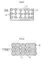
- a surface of a steel sheet S (a surface of a workpiece W) is treated with a zinc phosphate-based treatment agent, a crystalline zinc phosphate film 1 having a large number of pointed-shaped portions lying side-by-side is formed to define a large number of low-resistance areas (lower regions of boundary spaces between respective adjacent ones of the pointed portions) 2, as shown in FIG. 3 which is an explanatory diagram conceptually showing a configuration, etc., of the low-resistance areas of the zinc phosphate film.
- FIG. 4 is an explanatory diagram conceptually showing deposition of a cationic electrodeposition coating film in the low voltage-applied region of the workpiece having the zinc phosphate film formed thereon.
- a ZrO 2 film 21 is formed as a flat continuous noncrystalline film, as shown in FIG. 8 which is an explanatory diagram conceptually showing low-resistance areas of the conventional ZrO 2 film.
- FIG. 8 is an explanatory diagram conceptually showing low-resistance areas of the conventional ZrO 2 film.
- a local low-resistance area 22 is formed in the conventional ZrO 2 film 21, the number of the local low-resistance areas 22 is extremely small.
- the conventional ZrO 2 film 21 has a relatively low electrical conductivity, and thereby an amount of coating film to be deposited on a portion of the workpiece (steel sheet S) far from the anode and belonging to the low voltage-applied region becomes smaller.
- a resistance in each of the few local low-resistance areas of the conventional ZrO 2 film 21 is greater than that in each of the low-resistance areas of the zinc phosphate film 1. Therefore, no current flows through the conventional ZrO 2 film 21 unless a certain level or more of voltage is applied thereto.
- FIG. 9 which is an explanatory diagram conceptually showing deposition of a cationic electrodeposition coating film in the low voltage-applied region of the workpiece (steel sheet S) having the conventional ZrO 2 film formed thereon, it is more difficult to deposit a coating film F on a portion of the workpiece far from the anode and belonging to the low voltage-applied region, as compared with the workpiece having the zinc phosphate film 1 (see FIG. 4 for comparison). That is, in the workpiece having the conventional ZrO 2 film 21, a cationic electrodeposition coating film is unlikely to be deposited on a portion of the workpiece other than the local low-resistance areas 22, as shown in FIG. 9 .
- a resistance in a maximum-resistance area (an area having a maximum film thickness of about 50 nm: see FIG 8 ) 23 of the conventional ZrO 2 film 21 is less than that in a maximum-resistance area (a pointed area having a maximum film thickness of about 1 to 2 nm: see FIG. 3 ) 3. Therefore, in the high voltage-applied region, a coating film F is more widely deposited on the conventional ZrO 2 film 21 than on the zinc phosphate film 1.
- a film thickness of the coating film F in the workpiece having the conventional ZrO 2 film 21 becomes fairly greater than that of a coating film in the workpiece having the zinc phosphate film 1.
- FIGS. 5, 6 , 10 and 11 conceptually show the above hypothesis.
- FIG. 5 is an explanatory diagram conceptually showing an initial stage of deposition of a cationic electrodeposition coating film in the high voltage-applied region of the workpiece having the zinc phosphate film formed thereon
- FIG. 6 is an explanatory diagram conceptually showing an intermediate stage of the deposition of the cationic electrodeposition coating film in the high voltage-applied region of the workpiece having the zinc phosphate film formed thereon
- FIG. 10 is an explanatory diagram conceptually showing an initial stage of deposition of a cationic electrodeposition coating film in the high voltage-applied region of the workpiece having the conventional ZrO 2 film formed thereon
- FIG. 11 is an explanatory diagram conceptually showing an intermediate stage of the deposition of the cationic electrodeposition coating film in the high voltage-applied region of the workpiece having the conventional ZrO 2 film formed thereon.
- a size (spatial size) of each of the low-resistance areas 2 of the zinc phosphate film is relatively small.
- electrolysis occurs in each of the low-resistance areas 2 to generate hydroxide ions, and acid giving water solubility to paint is neutralized by the hydroxide ions.
- H 2 is generated. That is, H 2 is continuously generated from the initial stage.
- FIG. 7 which is an explanatory diagram conceptually showing a last stage of the deposition of the cationic electrodeposition coating film in the high voltage-applied region of the workpiece having the zinc phosphate film formed thereon.
- each of the few low-resistance areas 22 of the conventional ZrO 2 film 21 is thinner and larger (wider) than the low-resistance area 2 of the zinc phosphate film 1.
- a coating film F is deposited through concentration of electric charges in the large low-resistance area 22, generation of hydroxide ions and neutralization of acid giving water solubility to paint by the hydroxide ions (a process of generating H 2 )
- the large low-resistance area 22 is not easily filled with the coating film F, as shown in FIG. 12 which is an explanatory diagram conceptually showing a last stage of the deposition of the cationic electrodeposition coating film in the high voltage-applied region of the workpiece having the conventional ZrO 2 film formed thereon.
- a resistance is not increased along with the deposition of the coating film on the workpiece (steel sheet S) to allow the coating film F to be continuously deposited, so that a film thickness of the coating film F becomes fairly greater than that of a coating film in the workpiece having the zinc phosphate film 1.
- This makes it difficult to allow electrons to transfer to a portion of the workpiece far from the anode (in a vehicle body, an inner panel) to which electrons essentially hardly transfer, and thereby no coating film is deposited thereon.
- the inventors have formed a chemical conversion film using the chemical conversion treatment agent according to this embodiment, in such a manner that a ZrO 2 film 21 is employed as a matrix, and at least one kind of fine particles selected from the group consisting of metal fine particles, semiconductor fine particles and electrically conductive organic fine particles is codeposited within the ZrO 2 film 21.
- the reason for employing the ZrO 2 film 21 as a matrix is to ensure basic functions, such as corrosion resistance. Further, the reason for codepositing the at least one kind of fine particles selected from the group consisting of metal fine particles, semiconductor fine particles and electrically conductive organic fine particles within the ZrO 2 film 21 is to reduce a rate of ZrO 2 so as to reduce an amount of coating film F to be deposited on a portion of a workpiece adjacent to an anode (in a vehicle body, an outer panel), and increase the number of electrical-conductive areas each capable of conducting a current therethrough only when a given value or more of voltage is applied thereto, with a focus on an electron tunneling effect.
- an amount of coating film F to be deposited on a portion of a workpiece adjacent to an anode (in a vehicle body, an outer panel) can be reduced to prevent excessive deposition of the coating film F.
- electrical conductivity (tunneling effect) of the at least one kind of fine particles selected from the group consisting of metal fine particles, semiconductor fine particles and electrically conductive organic fine particles deposition of the coating film F can be promoted in a portion of the workpiece far from the anode (in a vehicle body, an inner panel).
- the ZrO 2 film 21 makes it possible to allow the ZrO 2 film 21 to have a film thickness characteristic (electrodeposition coatability) of a coating film close to that based on a zinc phosphate film 1.
- the ZrO 2 film 21 codeposited with the at least one kind of fine particles can achieve satisfactory corrosion resistance and electrodeposition coatability, as well as being able to prevent the problems about eutrophication and sludge production.
- the metal fine particles may be fine particles of at least one of Mg, Al, Ca, Co, Ni, Cu and Zn.
- the semiconductor fine particles may be fine particles of an oxide semiconductor, such as ZnO or TiO 2 .
- an oxide of Ti, Zn, etc., which exhibits semiconductor properties, may be used in the form of ions.
- the electrically conductive organic fine particles may be polyaniline fine particles or fine particles of a metal protected by an organic matter.
- the fine particles preferably have an average particle size of 40 nm or less, more preferably 20 to 40 nm.
- a film thickness of a coating film in a workpiece having the conventional ZrO 2 film becomes fairly larger than that of a coating film in a workpiece having the zinc phosphate film, in a portion of the workpiece adjacent to the anode and belonging to the high voltage-applied region, and becomes fairly smaller than that of the coating film in the workpiece having the zinc phosphate film, in a portion of the workpiece far from the anode and belonging to the low voltage-applied region
- a size of each of the low-resistance areas 22 of the conventional ZrO 2 film devoid of any of metal fine particles, semiconductor fine particles and electrically conductive organic fine particles is reduced in some way to prevent electric charges from concentrating in the low-resistance area 22.
- the ZrO 2 film 21 codeposited with the at least one kind of fine particles selected from the group consisting of metal fine particles, semiconductor fine particles and electrically conductive organic fine particles, it is considered that, although each of the low-resistance areas 22 is relatively large, the number of electrical-conductive areas is increased during voltage application by a tunneling effect based on the at least one kind of fine particles, so as to avoid concentration of electric charges in the large low-resistance area 22.
- the ZrO 2 film 21 can have a film thickness characteristic of a coating film close to that based on a zinc phosphate film 1, while preventing the aforementioned problems.
- a chemical conversion film formed using the chemical conversion treatment agent according to this embodiment i.e., a ZrO 2 film codeposited with the at least one kind of fine particles selected from the group consisting of metal fine particles, semiconductor fine particles and electrically conductive organic fine particles, is compared with the conventional ZrO 2 film and the zinc phosphate.
- the chemical conversion film formed using the chemical conversion treatment agent according to this embodiment is a ZrO 2 film codeposited with n-type ZnO which is semiconductor fine particles.
- FIG. 13 shows a film thickness characteristic of a coating film formed on the ZrO 2 film codeposited with n-type ZnO (semiconductor fine particles), as chemical conversion film, for the purpose of supporting the above hypothesis.
- FIG. 13 is a graph showing a relationship between a film thickness of a cationic electrodeposition coating film and an applied voltage, in each of three types of workpieces on which the ZrO 2 film codeposited with n-type ZnO, the conventional ZrO 2 film and the zinc phosphate film are formed, respectively, as a chemical conversion film.
- the vertical axis and the horizontal axis are the same as those in FIG. 2 .
- n-type ZnO a content ratio of the n-type ZnO to the chemical conversion film was 5.6 mass%, and the n-type ZnO had the following composition and characteristics.
- the chemical conversion film containing the n-type ZnO in an amount of 5.6 mass% was formed using a chemical conversion treatment agent which has a composition consisting of 100 ppm of H 2 ZrF 6 as a metal equivalent to Zr, 7 of fluorine in a mole ratio to Zr, and 50 ppm of amino group-containing alkoxysilane as a water-soluble resin, in solid concentration, with the remainder being a solvent (consisting primarily of water).
- a chemical conversion treatment agent which has a composition consisting of 100 ppm of H 2 ZrF 6 as a metal equivalent to Zr, 7 of fluorine in a mole ratio to Zr, and 50 ppm of amino group-containing alkoxysilane as a water-soluble resin, in solid concentration, with the remainder being a solvent (consisting primarily of water).
- a conventional ZrO 2 film and the zinc phosphate film was formed using a conventional chemical conversion treatment agent.
- the ZrO 2 film codeposited with the n-type ZnO as the semiconductor fine particles had a film thickness characteristic (electrodeposition coatability) of a coating film close to that based on the zinc phosphate film 1.
- the ZrO 2 film 21 codeposited with the n-type ZnO as the semiconductor fine particles is used as a chemical conversion film, it is considered that the number of local electrical-conductive areas are increased during voltage application (only one local electrical-conductive area is shown in FIG. 14 ) to promote deposition of a coating film (resin) F on a surface of a steel sheet S, as shown in FIG.
- FIG. 14 which is an explanatory diagram conceptually showing deposition of a cationic electrodeposition coating film in a low voltage-applied region of a workpiece (steel sheet S) having the ZrO 2 film codeposited with the n-type ZnO.
- an applied voltage is preferably set at a value greater than a corrosion potential (e.g., about 1 V), to increase the number of electrical-conductive areas.
- the reference code P indicates a coating material having water solubility given by acid.
- FIG. 15 is a graph showing a current density distribution during non-voltage application, in the ZrO 2 film codeposited with the n-type ZnO.
- the same result as that in FIG. 15 was obtained. That is, in either measurement, no current was detected during non-voltage application.
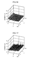
- FIG. 16 is a graph showing a current density distribution during voltage (1 V) application, in the conventional ZrO 2 film
- FIG. 17 is a graph showing a current density distribution during voltage (1 V) application, in the ZrO 2 film codeposited with the n-type ZnO.
- FIG. 16 even if a voltage of 1V was applied, no current was detected in the conventional ZrO 2 film.
- a current was detected in the ZrO 2 film codeposited with the n-type ZnO. This verified that the n-type ZnO contributes to an increase in the number of local electrical-conductive areas, so as to promote deposition of a coating film F.
- FIG. 18 is a table showing an influence of a content ratio of the n-type ZnO (semiconductor fine particles) to the ZrO 2 film codeposited with the n-type ZnO, on a film thickness (electrodeposition coatability) of a coating film and corrosion resistance.
- a film thickness (electrodeposition coatability) of a coating film becomes larger (better) along with an increase in amount (mass%) of the n-type ZnO, and a problem about corrosion resistance occurs when the amount (mass%) of the n-type ZnO is increased up to a given value or more although the corrosion resistance is in an allowable range when the amount is less than the given value.
- the corrosion resistance was evaluated based on measurement of a swelling rate (%) of a coating film F after 60 cycles of cyclic corrosion tests (CCTs) (1 cycle of the CCT ⁇ JIS K5600-7-9 cycle A x 3). Specifically, a smaller swelling rate (%) of the coating film F after 60 cycles of the CCTs indicates more excellent corrosion resistance.
- CCTs cyclic corrosion tests
- FIG. 19 is a graph showing a content ratio of the semiconductor fine particles and a coating-film swelling rate, in a workpiece on which the ZrO 2 film codeposited with the n-type ZnO as the semiconductor fine particles is formed.
- the vertical axis represents a coating-film swelling rate (%) after 60 cycles of the CCTs (1 cycle of the CCT - JIS K5600-7-9 cycle A x 3), and horizontal axis represents a content ratio (mass%) of the n-type ZnO to the ZrO 2 film codeposited with the n-type ZnO. That is, FIG. 19 shows a technique of determining an upper limit of an amount (mass%) of the n-type ZnO in view of corrosion resistance.
- the relationship between the amount (mass%) of the n-type ZnO and the coating-film swelling rate (%) after 60 cycles of the CCTs in FIG. 18 is plotted in FIG. 19 , and an upper limit of the amount (mass%) of the n-type ZnO is determined based on a coating-film swelling rate of 30 (%) which is used as an allowable limit (reference value) of corrosion resistance.
- a coating-film swelling rate of 30 (%) is used as an allowable limit (reference value) of corrosion resistance. This is based on the following reason.
- a 12-year warranty against a rust hole of an outer panel of a vehicle body becomes mainstream, and it has been confirmed by past records that the warranty is satisfied when the coating-film swelling rate is less than 30 (%).
- the amount (mass%) of the n-type ZnO at the allowable limit of corrosion resistance is 8.2 mass%. That is, it is necessary to set the amount of the n-type ZnO at 8.2 mass% or less in order to ensure corrosion resistance.
- the fine particles are the semiconductor fine particles
- the same effects could be obtained using metal fine particles or electrically conductive organic fine particles.
- a workpiece having a ZrO 2 film codeposited with the metal fine particles or electrically conductive organic fine particles allowed a high-quality coating film to be formed by a subsequent cationic electrodeposition coating process. That is, a formation (deposition) of a coating film in a subsequent cationic electrodeposition coating process can be accelerated to improve electrodeposition coatability in a portion of a workpiece belonging to the low voltage-applied region.
- the metal fine particles or the electrically conductive organic fine particles had the same desirable range of the content ratio as that of the semiconductor fine particles. Specifically, when an amount of the metal fine particles or the electrically conductive organic fine particles is set at 8.2 mass% or less, a content ratio (volume%) of the metal fine particles or the electrically conductive organic fine particles to a chemical conversion film can be set to be equal to or less than a content ratio (volume%) of the n-type ZnO to the chemical conversion film, so as to ensure corrosion resistance.
- a chemical conversion treatment agent which comprises: a film-forming component to form a chemical conversion film in which the number of local low-resistance areas each having an insulation resistance value of 5000 ⁇ or less is 20 or less/100 ⁇ m 2 ; and at least one kind of fine particles selected from the group consisting of metal fine particles, semiconductor fine particles and electrically conductive organic fine particles.
- the chemical conversion treatment agent can form a chemical conversion film which allows a high-quality coating film to be formed by a subsequent cationic electrodeposition coating process.
- the chemical conversion treatment agent can form a chemical conversion film which allows a formation (deposition) of a coating film in a subsequent cationic electrodeposition coating process to be accelerated so as to improve electrodeposition coatability in a portion of a workpiece belonging to a low voltage-applied region.
- the reason is considered to be that, even if a chemical conversion film having a relatively small number of local low-resistance areas is formed by the chemical conversion treatment agent, the at least one kind of fine particles selected from the group consisting of metal fine particles, semiconductor fine particles and electrically conductive organic fine particles is contained in the chemical conversion film, and the number of local electrical-conductive areas can be increased during voltage application in the electrodeposition coating process, by utilizing a tunneling effect based on the fine particles.
- the film-forming component contains, as a primary component, a compound having at least one selected from the group consisting of Zr, Ti, Hf and Si.
- a chemical conversion film formed using this film-forming component has a relatively small number of the local low-resistance areas, the film-forming component allows the chemical conversion film to have propertied capable of preventing eutrophication and suppressing sludge production associated with the chemical conversion treatment while ensuring corrosion resistance.
- the film-forming component contains H 2 ZrF 6 .
- the fine particles have an average primary particle size of 20 to 40 nm. In this case, the above advantages can be effectively obtained.
- a surface-treated metal material which comprises a chemical conversion film formed using a chemical conversion treatment agent.
- the chemical conversion treatment agent includes: a film-forming component to form a chemical conversion film in which the number of local low-resistance areas each having an insulation resistance value of 5000 ⁇ or less is 20 or less/100 ⁇ m 2 ; and at least one kind of fine particles selected from the group consisting of metal fine particles, semiconductor fine particles and electrically conductive organic fine particles.
- the chemical conversion film is codeposited with the at least one kind of fine particles selected from the group consisting of metal fine particles, semiconductor fine particles and electrically conductive organic fine particles.
- the surface-treated metal material can have a high-quality coating film formed by a cationic electrodeposition coating process. Specifically, the surface-treated metal material has a coating film excellent in electrodeposition coatability even in a portion of a workpiece belonging to a low voltage-applied region.
- the reason is considered to be that, even if a chemical conversion film formed on a surface of the surface-treated metal material has a relatively small number of local low-resistance areas, the at least one kind of fine particles selected from the group consisting of metal fine particles, semiconductor fine particles and electrically conductive organic fine particles is contained in the chemical conversion film, and the number of local electrical-conductive areas can be increased during voltage application in an electrodeposition coating process, by utilizing a tunneling effect based on the fine particles.
- the chemical conversion film includes an oxide which has, as a primary component, at least one element selected from the group consisting of Zr, Ti, Hf and Si.
- the chemical conversion film has a relatively small number of the local low-resistance areas, the above component allows the chemical conversion film to have propertied capable of preventing eutrophication and suppressing sludge production associated with the chemical conversion treatment while ensuring corrosion resistance.
- the fine particles are contained in the chemical conversion film in an amount of 8.2 mass% or less with respect to 100 mass% of the chemical conversion film.
- the fine particles contained in the chemical conversion film makes it possible to improve electrodeposition coatability in a portion of a workpiece belonging to a low voltage-applied region, while reliably preventing corrosion resistance from deteriorating beyond an allowable limit.
- the chemical conversion film comprises a primary component consisting of ZrO 2 .
Landscapes
- Chemical & Material Sciences (AREA)
- Engineering & Computer Science (AREA)
- Chemical Kinetics & Catalysis (AREA)
- Materials Engineering (AREA)
- Metallurgy (AREA)
- Organic Chemistry (AREA)
- Mechanical Engineering (AREA)
- General Chemical & Material Sciences (AREA)
- Electrochemistry (AREA)
- Application Of Or Painting With Fluid Materials (AREA)
- Chemical Treatment Of Metals (AREA)
Applications Claiming Priority (1)
| Application Number | Priority Date | Filing Date | Title |
|---|---|---|---|
| JP2008053227A JP2009209407A (ja) | 2008-03-04 | 2008-03-04 | 化成処理剤及び表面処理金属 |
Publications (1)
| Publication Number | Publication Date |
|---|---|
| EP2100986A1 true EP2100986A1 (de) | 2009-09-16 |
Family
ID=40637141
Family Applications (1)
| Application Number | Title | Priority Date | Filing Date |
|---|---|---|---|
| EP09002152A Withdrawn EP2100986A1 (de) | 2008-03-04 | 2009-02-16 | Chemisches Umwandlungsbehandlungsmittel und oberflächenbehandeltes Metallmaterial |
Country Status (3)
| Country | Link |
|---|---|
| US (1) | US20090223601A1 (de) |
| EP (1) | EP2100986A1 (de) |
| JP (1) | JP2009209407A (de) |
Cited By (4)
| Publication number | Priority date | Publication date | Assignee | Title |
|---|---|---|---|---|
| EP2302096A3 (de) * | 2009-09-03 | 2012-06-13 | Mazda Motor Corporation | Verfahren zur Behandlung einer metallischen Oberfläche |
| EP2787102A4 (de) * | 2011-11-30 | 2015-08-05 | Nihon Parkerizing | Zusatzstoff und verfahren zur herstellung eines oberflächenbehandelten stahlblechs |
| US10125424B2 (en) | 2012-08-29 | 2018-11-13 | Ppg Industries Ohio, Inc. | Zirconium pretreatment compositions containing molybdenum, associated methods for treating metal substrates, and related coated metal substrates |
| US10400337B2 (en) | 2012-08-29 | 2019-09-03 | Ppg Industries Ohio, Inc. | Zirconium pretreatment compositions containing lithium, associated methods for treating metal substrates, and related coated metal substrates |
Families Citing this family (1)
| Publication number | Priority date | Publication date | Assignee | Title |
|---|---|---|---|---|
| US11518960B2 (en) | 2016-08-24 | 2022-12-06 | Ppg Industries Ohio, Inc. | Alkaline molybdenum cation and phosphonate-containing cleaning composition |
Citations (7)
| Publication number | Priority date | Publication date | Assignee | Title |
|---|---|---|---|---|
| EP0285931A1 (de) * | 1987-03-31 | 1988-10-12 | Nippon Steel Corporation | Korrosionsbeständiges plattiertes Stahlband und Verfahren zu seiner Herstellung |
| EP0358338A2 (de) * | 1988-08-12 | 1990-03-14 | Alcan International Limited | Verfahren und Zusammensetzung für Oberflächenbehandlung |
| JP2004218074A (ja) | 2002-12-24 | 2004-08-05 | Nippon Paint Co Ltd | 化成処理剤及び表面処理金属 |
| US20040163735A1 (en) | 2002-12-24 | 2004-08-26 | Nippon Paint Co., Ltd. | Chemical conversion coating agent and surface-treated metal |
| EP1612294A1 (de) * | 2004-07-02 | 2006-01-04 | Italtecno S.R.L. | Formulierungsbad und verbundene Verfahren für die Umwandlungsschicht von Artikeln aus Aluminium und Aluminiumlegierungen |
| JP2008053227A (ja) | 2006-07-28 | 2008-03-06 | Matsushita Electric Works Ltd | 接点構造及びそれを用いた接点装置並びにマイクロリレー |
| EP1978131A1 (de) * | 2007-03-29 | 2008-10-08 | Atotech Deutschland Gmbh | Mittel zur Herstellung von Korrosionsschutzschichten auf Metalloberflächen |
-
2008
- 2008-03-04 JP JP2008053227A patent/JP2009209407A/ja not_active Abandoned
-
2009
- 2009-02-16 EP EP09002152A patent/EP2100986A1/de not_active Withdrawn
- 2009-02-17 US US12/372,381 patent/US20090223601A1/en not_active Abandoned
Patent Citations (7)
| Publication number | Priority date | Publication date | Assignee | Title |
|---|---|---|---|---|
| EP0285931A1 (de) * | 1987-03-31 | 1988-10-12 | Nippon Steel Corporation | Korrosionsbeständiges plattiertes Stahlband und Verfahren zu seiner Herstellung |
| EP0358338A2 (de) * | 1988-08-12 | 1990-03-14 | Alcan International Limited | Verfahren und Zusammensetzung für Oberflächenbehandlung |
| JP2004218074A (ja) | 2002-12-24 | 2004-08-05 | Nippon Paint Co Ltd | 化成処理剤及び表面処理金属 |
| US20040163735A1 (en) | 2002-12-24 | 2004-08-26 | Nippon Paint Co., Ltd. | Chemical conversion coating agent and surface-treated metal |
| EP1612294A1 (de) * | 2004-07-02 | 2006-01-04 | Italtecno S.R.L. | Formulierungsbad und verbundene Verfahren für die Umwandlungsschicht von Artikeln aus Aluminium und Aluminiumlegierungen |
| JP2008053227A (ja) | 2006-07-28 | 2008-03-06 | Matsushita Electric Works Ltd | 接点構造及びそれを用いた接点装置並びにマイクロリレー |
| EP1978131A1 (de) * | 2007-03-29 | 2008-10-08 | Atotech Deutschland Gmbh | Mittel zur Herstellung von Korrosionsschutzschichten auf Metalloberflächen |
Non-Patent Citations (1)
| Title |
|---|
| HOU F ET AL: "Effect of the dispersibility of ZrO2 nanoparticles in Ni-ZrO2 electroplated nanocomposite coatings on the mechanical properties of nanocomposite coatings", APPLIED SURFACE SCIENCE, ELSEVIER, AMSTERDAM, NL, vol. 252, no. 10, 15 March 2006 (2006-03-15), pages 3812 - 3817, XP024893504, ISSN: 0169-4332, [retrieved on 20060315] * |
Cited By (6)
| Publication number | Priority date | Publication date | Assignee | Title |
|---|---|---|---|---|
| EP2302096A3 (de) * | 2009-09-03 | 2012-06-13 | Mazda Motor Corporation | Verfahren zur Behandlung einer metallischen Oberfläche |
| US8506728B2 (en) | 2009-09-03 | 2013-08-13 | Mazda Motor Corporation | Surface treatment method of metal material |
| EP2787102A4 (de) * | 2011-11-30 | 2015-08-05 | Nihon Parkerizing | Zusatzstoff und verfahren zur herstellung eines oberflächenbehandelten stahlblechs |
| US10125424B2 (en) | 2012-08-29 | 2018-11-13 | Ppg Industries Ohio, Inc. | Zirconium pretreatment compositions containing molybdenum, associated methods for treating metal substrates, and related coated metal substrates |
| US10400337B2 (en) | 2012-08-29 | 2019-09-03 | Ppg Industries Ohio, Inc. | Zirconium pretreatment compositions containing lithium, associated methods for treating metal substrates, and related coated metal substrates |
| US10920324B2 (en) | 2012-08-29 | 2021-02-16 | Ppg Industries Ohio, Inc. | Zirconium pretreatment compositions containing molybdenum, associated methods for treating metal substrates, and related coated metal substrates |
Also Published As
| Publication number | Publication date |
|---|---|
| JP2009209407A (ja) | 2009-09-17 |
| US20090223601A1 (en) | 2009-09-10 |
Similar Documents
| Publication | Publication Date | Title |
|---|---|---|
| US8506728B2 (en) | Surface treatment method of metal material | |
| KR101431942B1 (ko) | 용기용 강판의 제조 방법 | |
| JP4757893B2 (ja) | 金属酸化物及び/又は金属水酸化物被覆金属材料とその製造方法 | |
| KR101599167B1 (ko) | 아연계 도금 강판용의 표면 처리액과 아연계 도금 강판 및 그 제조 방법 | |
| US20090162563A1 (en) | Electrochemically produced layers for corrosion protection or as a primer | |
| HUE030515T2 (en) | A method of pretreating a coating of zinc surfaces with a metal layer | |
| EP2100986A1 (de) | Chemisches Umwandlungsbehandlungsmittel und oberflächenbehandeltes Metallmaterial | |
| JP2012062519A (ja) | 容器用鋼板 | |
| KR100814489B1 (ko) | 화성처리 금속판 | |
| JP2010255105A (ja) | 亜鉛系めっき鋼板 | |
| EP2708619B1 (de) | Chemisches umwandlungsbehandlungsmittel zur oberflächenbehandlung eines metallsubstrats und verfahren zur oberflächenbehandlung eines metallsubstrats damit | |
| EP1548157A1 (de) | Korrosionsschutz durch elektrochemisch abgeschiedene Metalloxidschichten auf Metallsubstraten | |
| EP2980272B1 (de) | Mittel zur behandlung einer metalloberfläche und verfahren zur behandlung einer metalloberfläche | |
| ES2584937T3 (es) | Fosfatación con circonio de piezas constructivas metálicas, en particular hierro | |
| JP4349149B2 (ja) | 導電性に優れる表面処理鋼板の製造方法 | |
| JP2004277876A (ja) | 表面処理亜鉛系めっき鋼板 | |
| JP2004060052A (ja) | Si含有化成皮膜を有する錫系めっき鋼板の製造方法 | |
| EP0564301B1 (de) | Verfahren zur Herstellung eines Films durch chemische Umwandlung | |
| US20070122645A1 (en) | Coated metal plate with excellent corrosion resistance and reduced environmental impact | |
| JP4400372B2 (ja) | 半田付け性、耐食性および耐ホイスカー性に優れるSn系めっき鋼板およびその製造方法 | |
| JP3305702B2 (ja) | 燃料タンク用アルミニウム系めっき鋼板 | |
| JP3302676B2 (ja) | 耐食性に優れた化成処理鋼板 | |
| JP7732747B2 (ja) | 表面処理鋼板、金属容器および表面処理鋼板の製造方法 | |
| JP2018135570A (ja) | Sn系合金めっき鋼板及びSn系合金めっき鋼板の製造方法 | |
| JP5526664B2 (ja) | 金属部材の表面処理方法 |
Legal Events
| Date | Code | Title | Description |
|---|---|---|---|
| PUAI | Public reference made under article 153(3) epc to a published international application that has entered the european phase |
Free format text: ORIGINAL CODE: 0009012 |
|
| AK | Designated contracting states |
Kind code of ref document: A1 Designated state(s): AT BE BG CH CY CZ DE DK EE ES FI FR GB GR HR HU IE IS IT LI LT LU LV MC MK MT NL NO PL PT RO SE SI SK TR |
|
| AX | Request for extension of the european patent |
Extension state: AL BA RS |
|
| 17P | Request for examination filed |
Effective date: 20100316 |
|
| AKX | Designation fees paid |
Designated state(s): DE |
|
| 17Q | First examination report despatched |
Effective date: 20120404 |
|
| STAA | Information on the status of an ep patent application or granted ep patent |
Free format text: STATUS: THE APPLICATION IS DEEMED TO BE WITHDRAWN |
|
| 18D | Application deemed to be withdrawn |
Effective date: 20120815 |