EP2100988B1 - Dünn geschichtete Struktur - Google Patents
Dünn geschichtete Struktur Download PDFInfo
- Publication number
- EP2100988B1 EP2100988B1 EP09100179.2A EP09100179A EP2100988B1 EP 2100988 B1 EP2100988 B1 EP 2100988B1 EP 09100179 A EP09100179 A EP 09100179A EP 2100988 B1 EP2100988 B1 EP 2100988B1
- Authority
- EP
- European Patent Office
- Prior art keywords
- layer
- vacuum
- substance
- deposited
- substrate
- Prior art date
- Legal status (The legal status is an assumption and is not a legal conclusion. Google has not performed a legal analysis and makes no representation as to the accuracy of the status listed.)
- Active
Links
- 229910052751 metal Inorganic materials 0.000 claims description 48
- 239000002184 metal Substances 0.000 claims description 48
- 239000000758 substrate Substances 0.000 claims description 40
- KDLHZDBZIXYQEI-UHFFFAOYSA-N Palladium Chemical compound [Pd] KDLHZDBZIXYQEI-UHFFFAOYSA-N 0.000 claims description 33
- 239000001257 hydrogen Substances 0.000 claims description 30
- 229910052739 hydrogen Inorganic materials 0.000 claims description 30
- UFHFLCQGNIYNRP-UHFFFAOYSA-N Hydrogen Chemical compound [H][H] UFHFLCQGNIYNRP-UHFFFAOYSA-N 0.000 claims description 27
- BASFCYQUMIYNBI-UHFFFAOYSA-N platinum Chemical group [Pt] BASFCYQUMIYNBI-UHFFFAOYSA-N 0.000 claims description 22
- 239000000126 substance Substances 0.000 claims description 22
- XLYOFNOQVPJJNP-UHFFFAOYSA-N water Chemical compound O XLYOFNOQVPJJNP-UHFFFAOYSA-N 0.000 claims description 21
- 239000000203 mixture Substances 0.000 claims description 20
- RTAQQCXQSZGOHL-UHFFFAOYSA-N Titanium Chemical compound [Ti] RTAQQCXQSZGOHL-UHFFFAOYSA-N 0.000 claims description 18
- 229910052782 aluminium Inorganic materials 0.000 claims description 18
- 229910052719 titanium Inorganic materials 0.000 claims description 18
- 239000010936 titanium Substances 0.000 claims description 18
- XAGFODPZIPBFFR-UHFFFAOYSA-N aluminium Chemical group [Al] XAGFODPZIPBFFR-UHFFFAOYSA-N 0.000 claims description 17
- 229910052760 oxygen Inorganic materials 0.000 claims description 17
- 238000001771 vacuum deposition Methods 0.000 claims description 17
- QVGXLLKOCUKJST-UHFFFAOYSA-N atomic oxygen Chemical compound [O] QVGXLLKOCUKJST-UHFFFAOYSA-N 0.000 claims description 16
- 239000001301 oxygen Substances 0.000 claims description 16
- 229910044991 metal oxide Inorganic materials 0.000 claims description 13
- 229910052763 palladium Inorganic materials 0.000 claims description 12
- -1 platinum group metals Chemical class 0.000 claims description 12
- 150000004706 metal oxides Chemical class 0.000 claims description 11
- 239000000356 contaminant Substances 0.000 claims description 10
- 230000005855 radiation Effects 0.000 claims description 10
- 239000012298 atmosphere Substances 0.000 claims description 9
- 238000001704 evaporation Methods 0.000 claims description 6
- 230000015572 biosynthetic process Effects 0.000 claims description 4
- 238000001514 detection method Methods 0.000 claims description 4
- 239000012080 ambient air Substances 0.000 claims description 2
- 238000000034 method Methods 0.000 description 15
- 239000007789 gas Substances 0.000 description 14
- 239000011888 foil Substances 0.000 description 11
- PNEYBMLMFCGWSK-UHFFFAOYSA-N aluminium oxide Inorganic materials [O-2].[O-2].[O-2].[Al+3].[Al+3] PNEYBMLMFCGWSK-UHFFFAOYSA-N 0.000 description 10
- 238000005247 gettering Methods 0.000 description 10
- 229910052593 corundum Inorganic materials 0.000 description 8
- 229910001845 yogo sapphire Inorganic materials 0.000 description 8
- 238000010521 absorption reaction Methods 0.000 description 7
- 239000011248 coating agent Substances 0.000 description 7
- 238000000576 coating method Methods 0.000 description 7
- 230000003287 optical effect Effects 0.000 description 7
- 230000008569 process Effects 0.000 description 7
- CURLTUGMZLYLDI-UHFFFAOYSA-N Carbon dioxide Chemical compound O=C=O CURLTUGMZLYLDI-UHFFFAOYSA-N 0.000 description 6
- 238000001994 activation Methods 0.000 description 6
- 238000004519 manufacturing process Methods 0.000 description 6
- 239000000463 material Substances 0.000 description 6
- 238000010943 off-gassing Methods 0.000 description 6
- 230000004913 activation Effects 0.000 description 5
- 238000000151 deposition Methods 0.000 description 5
- 238000010438 heat treatment Methods 0.000 description 5
- HBEQXAKJSGXAIQ-UHFFFAOYSA-N oxopalladium Chemical compound [Pd]=O HBEQXAKJSGXAIQ-UHFFFAOYSA-N 0.000 description 5
- 229910003445 palladium oxide Inorganic materials 0.000 description 5
- 229910002092 carbon dioxide Inorganic materials 0.000 description 4
- 230000015556 catabolic process Effects 0.000 description 4
- 238000006243 chemical reaction Methods 0.000 description 4
- 238000006731 degradation reaction Methods 0.000 description 4
- 230000008021 deposition Effects 0.000 description 4
- 230000008020 evaporation Effects 0.000 description 4
- 238000005546 reactive sputtering Methods 0.000 description 4
- 238000001878 scanning electron micrograph Methods 0.000 description 4
- 238000002835 absorbance Methods 0.000 description 3
- 239000006096 absorbing agent Substances 0.000 description 3
- 238000001816 cooling Methods 0.000 description 3
- 150000002431 hydrogen Chemical class 0.000 description 3
- 230000004048 modification Effects 0.000 description 3
- 238000012986 modification Methods 0.000 description 3
- 239000011148 porous material Substances 0.000 description 3
- 238000006722 reduction reaction Methods 0.000 description 3
- 238000004544 sputter deposition Methods 0.000 description 3
- 239000010409 thin film Substances 0.000 description 3
- 229910052723 transition metal Inorganic materials 0.000 description 3
- 150000003624 transition metals Chemical class 0.000 description 3
- XKRFYHLGVUSROY-UHFFFAOYSA-N Argon Chemical compound [Ar] XKRFYHLGVUSROY-UHFFFAOYSA-N 0.000 description 2
- IJGRMHOSHXDMSA-UHFFFAOYSA-N Atomic nitrogen Chemical compound N#N IJGRMHOSHXDMSA-UHFFFAOYSA-N 0.000 description 2
- 235000011299 Brassica oleracea var botrytis Nutrition 0.000 description 2
- 240000003259 Brassica oleracea var. botrytis Species 0.000 description 2
- UGFAIRIUMAVXCW-UHFFFAOYSA-N Carbon monoxide Chemical compound [O+]#[C-] UGFAIRIUMAVXCW-UHFFFAOYSA-N 0.000 description 2
- XEEYBQQBJWHFJM-UHFFFAOYSA-N Iron Chemical compound [Fe] XEEYBQQBJWHFJM-UHFFFAOYSA-N 0.000 description 2
- PXHVJJICTQNCMI-UHFFFAOYSA-N Nickel Chemical compound [Ni] PXHVJJICTQNCMI-UHFFFAOYSA-N 0.000 description 2
- QCWXUUIWCKQGHC-UHFFFAOYSA-N Zirconium Chemical compound [Zr] QCWXUUIWCKQGHC-UHFFFAOYSA-N 0.000 description 2
- 229910052786 argon Inorganic materials 0.000 description 2
- 239000011230 binding agent Substances 0.000 description 2
- 239000001569 carbon dioxide Substances 0.000 description 2
- 238000010276 construction Methods 0.000 description 2
- 238000005137 deposition process Methods 0.000 description 2
- 238000009792 diffusion process Methods 0.000 description 2
- 238000000921 elemental analysis Methods 0.000 description 2
- 230000006870 function Effects 0.000 description 2
- 230000014509 gene expression Effects 0.000 description 2
- 239000011521 glass Substances 0.000 description 2
- 229910052741 iridium Inorganic materials 0.000 description 2
- 150000002739 metals Chemical class 0.000 description 2
- 229910052762 osmium Inorganic materials 0.000 description 2
- 230000003647 oxidation Effects 0.000 description 2
- 238000007254 oxidation reaction Methods 0.000 description 2
- 229910052697 platinum Inorganic materials 0.000 description 2
- 238000005086 pumping Methods 0.000 description 2
- 230000009467 reduction Effects 0.000 description 2
- 229910052703 rhodium Inorganic materials 0.000 description 2
- 239000010948 rhodium Substances 0.000 description 2
- 229910052707 ruthenium Inorganic materials 0.000 description 2
- 238000001275 scanning Auger electron spectroscopy Methods 0.000 description 2
- 239000004065 semiconductor Substances 0.000 description 2
- 238000001179 sorption measurement Methods 0.000 description 2
- 238000002207 thermal evaporation Methods 0.000 description 2
- 230000000007 visual effect Effects 0.000 description 2
- 229910052726 zirconium Inorganic materials 0.000 description 2
- JBRZTFJDHDCESZ-UHFFFAOYSA-N AsGa Chemical compound [As]#[Ga] JBRZTFJDHDCESZ-UHFFFAOYSA-N 0.000 description 1
- OYPRJOBELJOOCE-UHFFFAOYSA-N Calcium Chemical compound [Ca] OYPRJOBELJOOCE-UHFFFAOYSA-N 0.000 description 1
- 229910001218 Gallium arsenide Inorganic materials 0.000 description 1
- GPXJNWSHGFTCBW-UHFFFAOYSA-N Indium phosphide Chemical compound [In]#P GPXJNWSHGFTCBW-UHFFFAOYSA-N 0.000 description 1
- FYYHWMGAXLPEAU-UHFFFAOYSA-N Magnesium Chemical compound [Mg] FYYHWMGAXLPEAU-UHFFFAOYSA-N 0.000 description 1
- 229910001260 Pt alloy Inorganic materials 0.000 description 1
- KJTLSVCANCCWHF-UHFFFAOYSA-N Ruthenium Chemical compound [Ru] KJTLSVCANCCWHF-UHFFFAOYSA-N 0.000 description 1
- 239000011358 absorbing material Substances 0.000 description 1
- 230000004308 accommodation Effects 0.000 description 1
- 230000001464 adherent effect Effects 0.000 description 1
- 239000003570 air Substances 0.000 description 1
- 229910045601 alloy Inorganic materials 0.000 description 1
- 239000000956 alloy Substances 0.000 description 1
- 239000012300 argon atmosphere Substances 0.000 description 1
- 230000000712 assembly Effects 0.000 description 1
- 238000000429 assembly Methods 0.000 description 1
- 125000004429 atom Chemical group 0.000 description 1
- 229910052788 barium Inorganic materials 0.000 description 1
- DSAJWYNOEDNPEQ-UHFFFAOYSA-N barium atom Chemical compound [Ba] DSAJWYNOEDNPEQ-UHFFFAOYSA-N 0.000 description 1
- 230000004888 barrier function Effects 0.000 description 1
- 230000008901 benefit Effects 0.000 description 1
- 229910052793 cadmium Inorganic materials 0.000 description 1
- BDOSMKKIYDKNTQ-UHFFFAOYSA-N cadmium atom Chemical compound [Cd] BDOSMKKIYDKNTQ-UHFFFAOYSA-N 0.000 description 1
- 229910052791 calcium Inorganic materials 0.000 description 1
- 239000011575 calcium Substances 0.000 description 1
- 229910002091 carbon monoxide Inorganic materials 0.000 description 1
- 229910002090 carbon oxide Inorganic materials 0.000 description 1
- 238000001311 chemical methods and process Methods 0.000 description 1
- 238000009388 chemical precipitation Methods 0.000 description 1
- 239000003795 chemical substances by application Substances 0.000 description 1
- 150000001875 compounds Chemical class 0.000 description 1
- 239000002274 desiccant Substances 0.000 description 1
- 230000001066 destructive effect Effects 0.000 description 1
- 238000011161 development Methods 0.000 description 1
- 230000018109 developmental process Effects 0.000 description 1
- 230000009977 dual effect Effects 0.000 description 1
- 230000000694 effects Effects 0.000 description 1
- 238000005566 electron beam evaporation Methods 0.000 description 1
- 238000002149 energy-dispersive X-ray emission spectroscopy Methods 0.000 description 1
- PCHJSUWPFVWCPO-UHFFFAOYSA-N gold Chemical compound [Au] PCHJSUWPFVWCPO-UHFFFAOYSA-N 0.000 description 1
- 229910052737 gold Inorganic materials 0.000 description 1
- 239000010931 gold Substances 0.000 description 1
- 229910052735 hafnium Inorganic materials 0.000 description 1
- VBJZVLUMGGDVMO-UHFFFAOYSA-N hafnium atom Chemical compound [Hf] VBJZVLUMGGDVMO-UHFFFAOYSA-N 0.000 description 1
- 230000036571 hydration Effects 0.000 description 1
- 238000006703 hydration reaction Methods 0.000 description 1
- 229930195733 hydrocarbon Natural products 0.000 description 1
- 150000002430 hydrocarbons Chemical class 0.000 description 1
- 230000006872 improvement Effects 0.000 description 1
- 238000007733 ion plating Methods 0.000 description 1
- 238000010884 ion-beam technique Methods 0.000 description 1
- GKOZUEZYRPOHIO-UHFFFAOYSA-N iridium atom Chemical compound [Ir] GKOZUEZYRPOHIO-UHFFFAOYSA-N 0.000 description 1
- 229910052742 iron Inorganic materials 0.000 description 1
- 230000002427 irreversible effect Effects 0.000 description 1
- 229910052749 magnesium Inorganic materials 0.000 description 1
- 239000011777 magnesium Substances 0.000 description 1
- 230000007246 mechanism Effects 0.000 description 1
- 238000001465 metallisation Methods 0.000 description 1
- 239000002808 molecular sieve Substances 0.000 description 1
- 239000002057 nanoflower Substances 0.000 description 1
- 239000002071 nanotube Substances 0.000 description 1
- 229910052759 nickel Inorganic materials 0.000 description 1
- 229910052757 nitrogen Inorganic materials 0.000 description 1
- 229910052755 nonmetal Inorganic materials 0.000 description 1
- 150000002843 nonmetals Chemical class 0.000 description 1
- 150000002894 organic compounds Chemical class 0.000 description 1
- SYQBFIAQOQZEGI-UHFFFAOYSA-N osmium atom Chemical compound [Os] SYQBFIAQOQZEGI-UHFFFAOYSA-N 0.000 description 1
- WHOPEPSOPUIRQQ-UHFFFAOYSA-N oxoaluminum Chemical compound O1[Al]O[Al]1 WHOPEPSOPUIRQQ-UHFFFAOYSA-N 0.000 description 1
- 229910052698 phosphorus Inorganic materials 0.000 description 1
- 239000004033 plastic Substances 0.000 description 1
- 238000007747 plating Methods 0.000 description 1
- 239000010453 quartz Substances 0.000 description 1
- 239000006100 radiation absorber Substances 0.000 description 1
- 238000001552 radio frequency sputter deposition Methods 0.000 description 1
- 229920005989 resin Polymers 0.000 description 1
- 239000011347 resin Substances 0.000 description 1
- MHOVAHRLVXNVSD-UHFFFAOYSA-N rhodium atom Chemical compound [Rh] MHOVAHRLVXNVSD-UHFFFAOYSA-N 0.000 description 1
- 229920002631 room-temperature vulcanizate silicone Polymers 0.000 description 1
- 238000007789 sealing Methods 0.000 description 1
- VYPSYNLAJGMNEJ-UHFFFAOYSA-N silicon dioxide Inorganic materials O=[Si]=O VYPSYNLAJGMNEJ-UHFFFAOYSA-N 0.000 description 1
- URGAHOPLAPQHLN-UHFFFAOYSA-N sodium aluminosilicate Chemical compound [Na+].[Al+3].[O-][Si]([O-])=O.[O-][Si]([O-])=O URGAHOPLAPQHLN-UHFFFAOYSA-N 0.000 description 1
- 239000011343 solid material Substances 0.000 description 1
- 229910052712 strontium Inorganic materials 0.000 description 1
- CIOAGBVUUVVLOB-UHFFFAOYSA-N strontium atom Chemical compound [Sr] CIOAGBVUUVVLOB-UHFFFAOYSA-N 0.000 description 1
- 238000003466 welding Methods 0.000 description 1
Images


Classifications
-
- C—CHEMISTRY; METALLURGY
- C23—COATING METALLIC MATERIAL; COATING MATERIAL WITH METALLIC MATERIAL; CHEMICAL SURFACE TREATMENT; DIFFUSION TREATMENT OF METALLIC MATERIAL; COATING BY VACUUM EVAPORATION, BY SPUTTERING, BY ION IMPLANTATION OR BY CHEMICAL VAPOUR DEPOSITION, IN GENERAL; INHIBITING CORROSION OF METALLIC MATERIAL OR INCRUSTATION IN GENERAL
- C23C—COATING METALLIC MATERIAL; COATING MATERIAL WITH METALLIC MATERIAL; SURFACE TREATMENT OF METALLIC MATERIAL BY DIFFUSION INTO THE SURFACE, BY CHEMICAL CONVERSION OR SUBSTITUTION; COATING BY VACUUM EVAPORATION, BY SPUTTERING, BY ION IMPLANTATION OR BY CHEMICAL VAPOUR DEPOSITION, IN GENERAL
- C23C14/00—Coating by vacuum evaporation, by sputtering or by ion implantation of the coating forming material
- C23C14/0021—Reactive sputtering or evaporation
-
- C—CHEMISTRY; METALLURGY
- C23—COATING METALLIC MATERIAL; COATING MATERIAL WITH METALLIC MATERIAL; CHEMICAL SURFACE TREATMENT; DIFFUSION TREATMENT OF METALLIC MATERIAL; COATING BY VACUUM EVAPORATION, BY SPUTTERING, BY ION IMPLANTATION OR BY CHEMICAL VAPOUR DEPOSITION, IN GENERAL; INHIBITING CORROSION OF METALLIC MATERIAL OR INCRUSTATION IN GENERAL
- C23C—COATING METALLIC MATERIAL; COATING MATERIAL WITH METALLIC MATERIAL; SURFACE TREATMENT OF METALLIC MATERIAL BY DIFFUSION INTO THE SURFACE, BY CHEMICAL CONVERSION OR SUBSTITUTION; COATING BY VACUUM EVAPORATION, BY SPUTTERING, BY ION IMPLANTATION OR BY CHEMICAL VAPOUR DEPOSITION, IN GENERAL
- C23C14/00—Coating by vacuum evaporation, by sputtering or by ion implantation of the coating forming material
- C23C14/0021—Reactive sputtering or evaporation
- C23C14/0036—Reactive sputtering
-
- C—CHEMISTRY; METALLURGY
- C23—COATING METALLIC MATERIAL; COATING MATERIAL WITH METALLIC MATERIAL; CHEMICAL SURFACE TREATMENT; DIFFUSION TREATMENT OF METALLIC MATERIAL; COATING BY VACUUM EVAPORATION, BY SPUTTERING, BY ION IMPLANTATION OR BY CHEMICAL VAPOUR DEPOSITION, IN GENERAL; INHIBITING CORROSION OF METALLIC MATERIAL OR INCRUSTATION IN GENERAL
- C23C—COATING METALLIC MATERIAL; COATING MATERIAL WITH METALLIC MATERIAL; SURFACE TREATMENT OF METALLIC MATERIAL BY DIFFUSION INTO THE SURFACE, BY CHEMICAL CONVERSION OR SUBSTITUTION; COATING BY VACUUM EVAPORATION, BY SPUTTERING, BY ION IMPLANTATION OR BY CHEMICAL VAPOUR DEPOSITION, IN GENERAL
- C23C14/00—Coating by vacuum evaporation, by sputtering or by ion implantation of the coating forming material
- C23C14/22—Coating by vacuum evaporation, by sputtering or by ion implantation of the coating forming material characterised by the process of coating
- C23C14/24—Vacuum evaporation
-
- C—CHEMISTRY; METALLURGY
- C23—COATING METALLIC MATERIAL; COATING MATERIAL WITH METALLIC MATERIAL; CHEMICAL SURFACE TREATMENT; DIFFUSION TREATMENT OF METALLIC MATERIAL; COATING BY VACUUM EVAPORATION, BY SPUTTERING, BY ION IMPLANTATION OR BY CHEMICAL VAPOUR DEPOSITION, IN GENERAL; INHIBITING CORROSION OF METALLIC MATERIAL OR INCRUSTATION IN GENERAL
- C23C—COATING METALLIC MATERIAL; COATING MATERIAL WITH METALLIC MATERIAL; SURFACE TREATMENT OF METALLIC MATERIAL BY DIFFUSION INTO THE SURFACE, BY CHEMICAL CONVERSION OR SUBSTITUTION; COATING BY VACUUM EVAPORATION, BY SPUTTERING, BY ION IMPLANTATION OR BY CHEMICAL VAPOUR DEPOSITION, IN GENERAL
- C23C14/00—Coating by vacuum evaporation, by sputtering or by ion implantation of the coating forming material
- C23C14/22—Coating by vacuum evaporation, by sputtering or by ion implantation of the coating forming material characterised by the process of coating
- C23C14/56—Apparatus specially adapted for continuous coating; Arrangements for maintaining the vacuum, e.g. vacuum locks
-
- C—CHEMISTRY; METALLURGY
- C23—COATING METALLIC MATERIAL; COATING MATERIAL WITH METALLIC MATERIAL; CHEMICAL SURFACE TREATMENT; DIFFUSION TREATMENT OF METALLIC MATERIAL; COATING BY VACUUM EVAPORATION, BY SPUTTERING, BY ION IMPLANTATION OR BY CHEMICAL VAPOUR DEPOSITION, IN GENERAL; INHIBITING CORROSION OF METALLIC MATERIAL OR INCRUSTATION IN GENERAL
- C23C—COATING METALLIC MATERIAL; COATING MATERIAL WITH METALLIC MATERIAL; SURFACE TREATMENT OF METALLIC MATERIAL BY DIFFUSION INTO THE SURFACE, BY CHEMICAL CONVERSION OR SUBSTITUTION; COATING BY VACUUM EVAPORATION, BY SPUTTERING, BY ION IMPLANTATION OR BY CHEMICAL VAPOUR DEPOSITION, IN GENERAL
- C23C14/00—Coating by vacuum evaporation, by sputtering or by ion implantation of the coating forming material
- C23C14/22—Coating by vacuum evaporation, by sputtering or by ion implantation of the coating forming material characterised by the process of coating
- C23C14/56—Apparatus specially adapted for continuous coating; Arrangements for maintaining the vacuum, e.g. vacuum locks
- C23C14/562—Apparatus specially adapted for continuous coating; Arrangements for maintaining the vacuum, e.g. vacuum locks for coating elongated substrates
-
- C—CHEMISTRY; METALLURGY
- C23—COATING METALLIC MATERIAL; COATING MATERIAL WITH METALLIC MATERIAL; CHEMICAL SURFACE TREATMENT; DIFFUSION TREATMENT OF METALLIC MATERIAL; COATING BY VACUUM EVAPORATION, BY SPUTTERING, BY ION IMPLANTATION OR BY CHEMICAL VAPOUR DEPOSITION, IN GENERAL; INHIBITING CORROSION OF METALLIC MATERIAL OR INCRUSTATION IN GENERAL
- C23C—COATING METALLIC MATERIAL; COATING MATERIAL WITH METALLIC MATERIAL; SURFACE TREATMENT OF METALLIC MATERIAL BY DIFFUSION INTO THE SURFACE, BY CHEMICAL CONVERSION OR SUBSTITUTION; COATING BY VACUUM EVAPORATION, BY SPUTTERING, BY ION IMPLANTATION OR BY CHEMICAL VAPOUR DEPOSITION, IN GENERAL
- C23C28/00—Coating for obtaining at least two superposed coatings either by methods not provided for in a single one of groups C23C2/00 - C23C26/00 or by combinations of methods provided for in subclasses C23C and C25C or C25D
- C23C28/30—Coatings combining at least one metallic layer and at least one inorganic non-metallic layer
- C23C28/32—Coatings combining at least one metallic layer and at least one inorganic non-metallic layer including at least one pure metallic layer
- C23C28/322—Coatings combining at least one metallic layer and at least one inorganic non-metallic layer including at least one pure metallic layer only coatings of metal elements only
-
- C—CHEMISTRY; METALLURGY
- C23—COATING METALLIC MATERIAL; COATING MATERIAL WITH METALLIC MATERIAL; CHEMICAL SURFACE TREATMENT; DIFFUSION TREATMENT OF METALLIC MATERIAL; COATING BY VACUUM EVAPORATION, BY SPUTTERING, BY ION IMPLANTATION OR BY CHEMICAL VAPOUR DEPOSITION, IN GENERAL; INHIBITING CORROSION OF METALLIC MATERIAL OR INCRUSTATION IN GENERAL
- C23C—COATING METALLIC MATERIAL; COATING MATERIAL WITH METALLIC MATERIAL; SURFACE TREATMENT OF METALLIC MATERIAL BY DIFFUSION INTO THE SURFACE, BY CHEMICAL CONVERSION OR SUBSTITUTION; COATING BY VACUUM EVAPORATION, BY SPUTTERING, BY ION IMPLANTATION OR BY CHEMICAL VAPOUR DEPOSITION, IN GENERAL
- C23C28/00—Coating for obtaining at least two superposed coatings either by methods not provided for in a single one of groups C23C2/00 - C23C26/00 or by combinations of methods provided for in subclasses C23C and C25C or C25D
- C23C28/30—Coatings combining at least one metallic layer and at least one inorganic non-metallic layer
- C23C28/34—Coatings combining at least one metallic layer and at least one inorganic non-metallic layer including at least one inorganic non-metallic material layer, e.g. metal carbide, nitride, boride, silicide layer and their mixtures, enamels, phosphates and sulphates
- C23C28/345—Coatings combining at least one metallic layer and at least one inorganic non-metallic layer including at least one inorganic non-metallic material layer, e.g. metal carbide, nitride, boride, silicide layer and their mixtures, enamels, phosphates and sulphates with at least one oxide layer
-
- C—CHEMISTRY; METALLURGY
- C23—COATING METALLIC MATERIAL; COATING MATERIAL WITH METALLIC MATERIAL; CHEMICAL SURFACE TREATMENT; DIFFUSION TREATMENT OF METALLIC MATERIAL; COATING BY VACUUM EVAPORATION, BY SPUTTERING, BY ION IMPLANTATION OR BY CHEMICAL VAPOUR DEPOSITION, IN GENERAL; INHIBITING CORROSION OF METALLIC MATERIAL OR INCRUSTATION IN GENERAL
- C23C—COATING METALLIC MATERIAL; COATING MATERIAL WITH METALLIC MATERIAL; SURFACE TREATMENT OF METALLIC MATERIAL BY DIFFUSION INTO THE SURFACE, BY CHEMICAL CONVERSION OR SUBSTITUTION; COATING BY VACUUM EVAPORATION, BY SPUTTERING, BY ION IMPLANTATION OR BY CHEMICAL VAPOUR DEPOSITION, IN GENERAL
- C23C30/00—Coating with metallic material characterised only by the composition of the metallic material, i.e. not characterised by the coating process
-
- H—ELECTRICITY
- H01—ELECTRIC ELEMENTS
- H01J—ELECTRIC DISCHARGE TUBES OR DISCHARGE LAMPS
- H01J7/00—Details not provided for in the preceding groups and common to two or more basic types of discharge tubes or lamps
- H01J7/14—Means for obtaining or maintaining the desired pressure within the vessel
- H01J7/18—Means for absorbing or adsorbing gas, e.g. by gettering
- H01J7/183—Composition or manufacture of getters
-
- Y—GENERAL TAGGING OF NEW TECHNOLOGICAL DEVELOPMENTS; GENERAL TAGGING OF CROSS-SECTIONAL TECHNOLOGIES SPANNING OVER SEVERAL SECTIONS OF THE IPC; TECHNICAL SUBJECTS COVERED BY FORMER USPC CROSS-REFERENCE ART COLLECTIONS [XRACs] AND DIGESTS
- Y10—TECHNICAL SUBJECTS COVERED BY FORMER USPC
- Y10T—TECHNICAL SUBJECTS COVERED BY FORMER US CLASSIFICATION
- Y10T428/00—Stock material or miscellaneous articles
- Y10T428/249921—Web or sheet containing structurally defined element or component
- Y10T428/249953—Composite having voids in a component [e.g., porous, cellular, etc.]
-
- Y—GENERAL TAGGING OF NEW TECHNOLOGICAL DEVELOPMENTS; GENERAL TAGGING OF CROSS-SECTIONAL TECHNOLOGIES SPANNING OVER SEVERAL SECTIONS OF THE IPC; TECHNICAL SUBJECTS COVERED BY FORMER USPC CROSS-REFERENCE ART COLLECTIONS [XRACs] AND DIGESTS
- Y10—TECHNICAL SUBJECTS COVERED BY FORMER USPC
- Y10T—TECHNICAL SUBJECTS COVERED BY FORMER US CLASSIFICATION
- Y10T428/00—Stock material or miscellaneous articles
- Y10T428/249921—Web or sheet containing structurally defined element or component
- Y10T428/249953—Composite having voids in a component [e.g., porous, cellular, etc.]
- Y10T428/249987—With nonvoid component of specified composition
- Y10T428/24999—Inorganic
Definitions
- the present invention relates to a thin-layer laminate having utility as a getter for undesired gaseous contaminants in a vacuum enclosure, and to a vacuum enclosure characterized by the presence of this getter.
- IR radiation detectors Infra-red radiation detectors.
- IR radiation detectors commonly comprise a dewar envelope having an inner wall and an outer wall, a vacuum space being present between the inner and outer walls; the inner wall defines an inner chamber of the dewar; an infra-red radiation detector element is mounted in the vacuum space and on the end face of said inner wall; a cooling element is provided in the inner chamber and serves to cool the inner wall and the detector element mounted thereon during operation of the detector.
- the cooled inner wall is often termed "the cold finger" of the detector.
- an infrared detector incorporates a non-evaporable chemically-active SAES getter (e.g. SAES Getters Inc., St 171- St 172 Brochure; www.saesgetter.com) which is mounted on the outer wall and in the vacuum space between the outer wall and the cold finger.
- SAES Getters Inc. St 171- St 172 Brochure; www.saesgetter.com
- Such chemical getters are typically activated by heating to a high temperature after evacuation and sealing of the dewar envelope. This is normally achieved with an electrical heating element embedded in the getter material formed as a unit with electrical connection leads passing through vacuum-tight seals in the dewar wall ( C. Taylor,. S. Whicker, "Thermal Energy Receiver ", US Patent No. 3,851,173 ).
- the getter is typically a reactive solid material that either adsorbs, absorbs, chemisorbs, or catalyzes a reaction that immobilizes or destroys one or more targeted contaminant compounds, in particular contaminant gases.
- hydrogen can be released from various sources within an enclosure containing electronic assemblies and subassemblies. Hydrogen does not readily escape from environmentally sealed enclosures and reacts with hydrogen sensitive components. Furthermore, the unique thermal properties of hydrogen can be the cause of increased thermal loss.
- Several metals and nonmetals, used in production of IR detector components can contain dissolved hydrogen that is released over time. The package materials can also sometimes release hydrogen.
- Plated nickel layers used as a barrier layer for gold plating operations and plastic resins are known to release hydrogen in amounts that can degrade the vacuum level and performance of semi-conductor and electrical components ( R.Ramesham, "Getters for Reliable Hermetic Packages", JPL Publication D-1792/NASA, pp 14-17, 1999 ).
- US Patent No. 5,365,742 (Boffito, et al. ) describes a device for the removal of hydrogen from a vacuum enclosure at cryogenic temperatures, which comprises a metal support (e.g. an Al strip) a composition able to absorb hydrogen, adherent to at least one surface of the support.
- the composition comprises a porous absorber of water vapor, preferably powdered alumina in contact with palladium oxide PdO which preferably covers, at least partially, the water absorber.
- Pd(OH) 2 mixed with alumina may be precipitated on and attached to the support, then reduced to Pd metal, and re-oxidized to PdO.
- US Patent No. 5,888,925 discloses a hydrogen absorbing material, and a method for its manufacture wherein platinum group metal oxide(s), a desiccant (such as a molecular sieve) and a matrix-forming binder (such as an RTV silicone) are mixed together; and the mixture is cured in an oxygen-containing gas (e.g. air) for a time (e.g. at least 24 hours) and a temperature (e.g. 150-204°C), such that the material is stabilized from self-catalytic degradation.
- an oxygen-containing gas e.g. air
- a time e.g. at least 24 hours
- a temperature e.g. 150-204°C
- US patent application n° 2004/0253476 A1 discloses getter multilayer structures comprising a first layer with large porosity, a second layer comprising zirconium or valadium and on top thereof a palladium or palladium oxide compound layer.
- European patent publication n° EP 0 837 502 relates to an improvement to hydrogen gettering comprising a material degradable in the presence of hydrogen and a layer of hydrogen getter containing a transition metal such as palladium, platinum and oxides thereof.
- Active metal means one or more of magnesium, strontium, calcium, barium, cadmium, iron, titanium, aluminum, hafnium and zirconium.
- Platinum group metal means one or more of ruthenium, rhodium, palladium, osmium, iridium and platinum.
- reference to vacuum deposition of substances on a substrate and similar expressions includes deposition either on one side of a substrate, and, where the context allows (such as in the case of a foil substrate) deposition either on one side on both sides of the substrate.
- “Vacuum deposition” and similar expressions includes techniques such as sputtering; (including cathode DC sputtering, RF sputtering, reactive sputtering, etc.), evaporative metal deposition (including reactive evaporative deposition, thermal resistive evaporation, electron beam evaporation, etc.), ion plating, and neutralized ion beam coating.
- the aluminum or titanium substrates (e.g. foil substrates) mentioned herein include alloys of aluminum and/or titanium known in the art.
- Another object of the invention is to provide a getter unit having a large active specific surface area, and yet can be accommodated in the small space of a compact high vacuum device such as a detector envelope, in the latter case without requiring an increased envelope size or an unconventional envelope outline for its accommodation.
- Still another object of this invention is to provide a gettering method that does not require adjunct heating devices or very high temperatures for initial activation.
- Yet another object is to provide a combined solution which provides high absorption of stray IR radiation in addition to the function as getter for undesired gases.
- the present invention provides, in one aspect, a vacuum enclosure which is defined by a wall having inner and outer surfaces, where the inner surface is in contact with the vacuum and the outer surface is in contact with ambient air, and comprising therein a getter for undesired gaseous contaminants including at least hydrogen and water, wherein the getter comprises a substrate integral with said inner surface having deposited thereon by vacuum deposition a thin-layer laminate including at least one layer of substance(s) selected from the group consisting of platinum group metals and oxides thereof, and at least one porous hydrophilic layer of a mixture of at least one active metal with at least one active metal oxide wherein the at least one layer of substance(s) is deposited on the substrate, and the at least one porous hydrophilic layer is deposited on the at least one layer of the substance(s), and wherein the substrate is aluminum or titanium.
- the getter also preferably includes at least one of the following features: - said at least one platinum group metal comprises or consists of palladium;
- the substrate may be in the form of a roll; and/or the substrate may be aluminum or titanium e.g. as foil, and/or the at least one active metal is selected from aluminum and titanium, and/or the vacuum enclosure forms part of an IR detection system.
- At least one layer when including oxide(s) may be formed by reactive vacuum deposition of at least one platinum group metal in presence of oxygen, when not including oxide(s) it may be formed by non-reactive vacuum deposition of at least one platinum group metal.
- a layered structure which comprises a thin-layer laminate vacuum deposited on a substrate, which has utility as a getter for undesired gaseous contaminants including at least hydrogen and water vapor, wherein said laminate includes at least one layer of substance(s) selected from the group consisting of platinum group metals and oxides thereof, and at least one porous hydrophilic layer comprising a mixture of at least one active metal with at least one active metal oxide wherein the at least one layer of substance(s) is deposited on the substrate, and the at least one porous hydrophilic layer is deposited on the at least one layer of substance(s), and wherein the substrate is aluminum or titanium.
- the "at least one layer of substance(s) selected from the group consisting of platinum group metals and oxides thereof' is a platinum group metal layer or layers.
- a presently preferred structure comprises titanium substrate, e.g. a titanium foil substrate, on which is deposited a Pd and/or PdO layer, on top of which is deposited a black hydrophilic layer.
- the at least one layer of oxide(s) of at least one platinum group metal is preferably deposited on the substrate, and the at least one layer of the porous hydrophilic layer is deposited on the at least one layer of oxide(s) of at least one platinum group metal.
- the porous hydrophilic layer is preferably optically black and/or absorbs IR radiation within the 1-14 ⁇ m (micron) wavelength range.
- the layered structure of the invention may also be additionally characterized by any one or more of the corresponding embodiments for the getter, as set forth above.
- the present thin film getter comprises two vacuum deposited layers: a base layer of PdO and/or pure Pd and an upper, inorganic, highly porous hydrophilic layer composed of metal and metal-oxide admixtures.
- the outer layer can simultaneously serve as a wideband (1-14 ⁇ m) IR/light absorbing layer which exhibits a deep black color or its optical characteristics can be tailored to the application.
- This stacked layer structure deposited directly on the inner walls of the device is intended to combine together both the optical absorbance and gettering capacity required inside the IR detector envelope, and eliminates the need for use of additional independent getter devices within this volume.
- the unique property of metallic palladium to absorb extremely large quantities of hydrogen at low temperatures is applied herein to produce an efficient getter structure.
- the getter under consideration realizes a unique combination of all or some of the following 5 mechanisms:
- the above mentioned oxide reduction reaction (a) is exothermic and is also essentially irreversible; it proceeds easily within a wide range of temperatures from 35 -55°C up to 200°C.
- Palladium oxide is preferably used as the basis of getter structure because of cost considerations.
- other metals oxides particularly those of the platinum group metals, such as Rh, Ru, Pd, Os and Ir, and alloys of platinum group metals, can be considered also.
- the amounts of materials required for achieving the required performance and therefore the thickness of the deposited layers depends greatly on the application and the total area of coated surfaces inside the hermetically sealed volume.
- the optimal thickness of platinum metal oxide layer e.g. PdO was found to be in the range of 0.1-10, e.g. 3-10 ⁇ m.
- Optimal thickness of the highly porous hydrophilic layer is 5-50, e.g. ⁇ 25 ⁇ m.
- the gettering capabilities (capacities) in this case were found to be comparable to St 172 getters commonly used in similar applications.
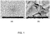
- Figures 1a -b show SEM images of the PdO layer produced through the reactive sputter deposition of pure Pd onto the substrate.
- the enhanced porosity leads to an increased pores volume and promotes faster reaction with the hydrogen to produce H 2 O molecules.
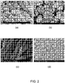
- Figures 2a -d show SEM images of various inorganic metal + metal oxide admixtures with highly porous structures, obtained by the deposition process as the top layer of the getter. These nano-structured and non-stoichiometric layers are effective in capturing the H 2 O. These structures were obtained by a vacuum deposition process developed by Acktar Ltd - (a) Ultra Black TM coating, (b) Fractal BlackTM coating, (c) Nano-tubes, (d) Nano-flowers.
- the PdO layer was analyzed by XPS and also by EDAX as shown in Table 1. It was found, that all the Pd atoms inside the coating are presumably in the +2 oxidation state.
- the top nano-structured layer of the getter is typically black in appearance and has a dual functionality in the case of IR detection applications. In addition to providing the above mentioned gettering capacity; it also exhibits unique optical characteristics with increased absorbance (as well as high emissivity) in the IR range which is a typical feature required on internal surfaces of the detector cold-shield to eliminate stray light propagation.
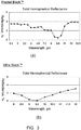
- Figure 3 shows the hemispherical reflectance of two distinct types of such layers demonstrating the optical properties of the outer getter coating with nearly zero reflectance at 8.5-10 ⁇ m wavelengths.
- the optical characteristics of the outer layer can be tailored appropriately.
- the present getters comprising preferably PdO and an additional water absorbing layer which is optically black and/or absorbs IR radiation within the 1-14 ⁇ m wavelength range , are produced exclusively by thin-film vacuum deposition techniques.
- the PdO layer is first deposited onto the preferred substrate by means of reactive sputtering in a technique which enhances the porosity and active surface area within the layer.
- the substrate enters a second process zone (within the same vacuum chamber or as a separate production step), where an additional layer is produced by a reactive evaporation of metal and metal oxide admixtures by a thermal evaporation process. See e.g. US Patent No. 6,764,712 (Katsir et al.
- a method for increasing the surface area of a substrate comprising the steps of: (a) placing the substrate in an inert atmosphere, having a pressure of between 0.13 Pa (10 -3 torr) and 0.13 Pa (10 -2 torr) into which oxygen has been introduced at a pressure of from one to two orders of magnitude less than the inert atmosphere pressure; and (b) evaporating active metal(s) only, onto a heated substrate under the oxygen-containing inert atmosphere, whereby the product comprises a mixture of fractal surface structure including at least one active metal and at least one active metal oxide deposited on the substrate.
- the second layer provides the H 2 O gettering capacity required and in addition it is designed to exhibit unique optical properties required for effective absorption of stray IR light inside the detector enclosure.
- Figure 4a shows an image of a typical cold-shield used in an IR detector application where the above mentioned layers are applied onto the inner surface of the shield.
- Figure 4b shows a schematic cross section of the stacked layers that comprise the thin film getter on the inside of the shield.
- the separate PdO and metal/metal oxide layers can also be applied at different ratios and on separate parts or opposite sides within the same vacuum enclosure to satisfy specific applications.
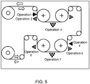
- FIG. 5 illustrates a scheme of an in-line layer deposition process carried out inside a vacuum chamber.
- Figure 6a shows the product which is obtained by this process, where the black layer observed on both sides of the substrate is the outer metal/metal oxide layer responsible for the gettering of H 2 O molecules and the absorption of stray light and IR radiation.
- Figure 6b illustrates the stacked layers as applied onto the continuous roll of substrate material.
- a layer of palladium oxide to a desired thickness in the range 3-10 ⁇ m was deposited by reactive sputtering of pure palladium in an oxygen rich atmosphere with an Argon background onto either one or both sides of clean aluminum foil substrates held at a temperature of 300°C and with pressure maintained between 0.3-1 Pa.
- Aluminum was then evaporated onto the palladium oxide surfaces of the substrates, held at the same temperature, by reactive thermal resistive evaporation, in an anhydrous inert atmosphere in presence of oxygen.
- the thus-produced Al/Al 2 O 3 layer has a fractal-like structure with a cauliflower-like morphology.
- the "cauliflower heads" are about 2 ⁇ m across.
- the "florets" are about 0.2 ⁇ m across, so that the surface is self-similar at least on a distance scale from 0.2 ⁇ m to 2 ⁇ m. This is confirmed by the visual appearance of the surface.
- the Al/Al 2 O 3 surface is black matte (diffusely reflective), showing that this surface has a fractal-like structure on the length scale of the wavelengths of visible light.
- the following is an EDS elemental analysis of the Al/Al 2 O 2 surface: N 1.18%, O 30.43%, Al 66.38%, P 1.79% and Ar 0.22%. It follows from stoichiometry that 30.3% of the aluminum was in the form of Al 2 O 3 and 69.7% was in the form of aluminum metal.
- the aluminum foil having deposited on one or both sides, sequential palladium oxide and Al/Al 2 O 3 layers is suitable for use as a getter (for hydrogen and water vapor, in particular) in high vacuum systems of special applications such as IR detectors.
- the sequential layers may be deposited directly on the inner surface (e.g. glass) of a potential high vacuum tube.
- a layer of pure palladium to a desired thickness in the range of 100-600 nm was deposited by sputtering of pure palladium in an inert argon atmosphere onto either one or both sides of a titanium sheet, from which the naturally occurring surface oxide was removed and with pressure maintained between 0.1-1 Pa.
- Aluminum was then evaporated onto the palladium surface(s) of the substrates, by reactive thermal resistive evaporation, in an anhydrous inert atmosphere in presence of oxygen.
- the thus-produced Al/Al 2 O 3 layer has a fractal-like structure with a cauliflower-like morphology.
- the "cauliflower heads" are about 2 ⁇ m across.
- the "florets" are about 0.2 ⁇ m across, so that the surface is self-similar at least on a distance scale from 0.2 ⁇ m to 2 ⁇ m. This is confirmed by the visual appearance of the surface.
- the Al/Al 2 O 3 surface is black matte (diffusely reflective), showing that this surface has a fractal-like structure on the length scale of the wavelengths of visible light.
- the EDS elemental analysis of the Al/Al 2 O 3 surface is essentially as stated in Example 1.
- the titanium sheet having deposited on one or both sides, sequential palladium and Al/Al 2 O 3 layers is suitable for use as a getter (for hydrogen and water vapour, in particular) in high vacuum systems of special applications such as IR detectors.
- the sequential layers may be deposited directly on the inner surface (titanium or other transition metal) of a potential vacuum enclosure.
- the present invention has the advantages of miniaturization (and thus relatively low thermal mass), absence of particulation during entire life time of the detector, high vibration stability, large surface area and thus high sorption capacity at room temperatures, able to be activated at temperatures below 125°C, simplified construction and low cost.
- the present invention further combines gettering of (at least) hydrogen and water vapor with the potential for absorption of stray light.
- the getter layer can be integrated with the internal low reflectance inorganic coating of cold shields and/or coated on internal dewar surfaces with appropriately tailored optical characteristics. Where appropriate, the gettering surface can be generated on a metal foil to be placed in the evacuated area.
- the functions of radiation absorber and gas absorber may be combined in the same unit, and that, moreover, in the IR region (1-14 ⁇ m wave-length) in particular, emissivity and absorbance may be tailored.
- emissivity and absorbance may be tailored inside a cold shield.
- a laminate with a black hydrophilic layer having high emissivity above 80%, typically ⁇ 95%) and outside there may be a laminate with relatively low emissivity (5-40%, typically ⁇ 10%).
- the structure of the present invention can be produced continuously, without separate chemical precipitation, reduction and oxidation steps, and without any requirement for use of a binder and a curing agent therefor.
Landscapes
- Chemical & Material Sciences (AREA)
- Engineering & Computer Science (AREA)
- Chemical Kinetics & Catalysis (AREA)
- Materials Engineering (AREA)
- Mechanical Engineering (AREA)
- Metallurgy (AREA)
- Organic Chemistry (AREA)
- Inorganic Chemistry (AREA)
- Manufacturing & Machinery (AREA)
- Solid-Sorbent Or Filter-Aiding Compositions (AREA)
- Physical Vapour Deposition (AREA)
- Laminated Bodies (AREA)
Claims (9)
- Vakuumeinhausung, die durch eine Wand mit einer Innen- und einer Außenoberfläche definiert ist, wobei die Innenoberfläche mit dem Vakuum und die Außenoberfläche mit der Umgebungsluft in Kontakt ist, umfassend einen Getter für unerwünschte, gasförmige Verunreinigungen, einschließlich mindestens Wasserstoff und Wasserdampf, wobei der Getter ein mit der Innenoberfläche ganzheitliches Substrat umfasst, auf dem mittels Vakuum eine dünne Laminatschicht abgeschieden wird, einschließlich mindestens einer Schicht Substanz(en), die von der Gruppe bestehend aus Metallen der Platingruppe und Oxiden davon ausgewählt ist, und mindestens einer porösen, hydrophilen Schicht eines Gemisches von mindestens einem aktiven Metall mit mindestens einem aktiven Metalloxid, wobei
die mindestens eine Schicht Substanz(en) auf dem Substrat abgeschieden ist und die mindestens eine poröse, hydrophile Schicht auf der mindestens einen Schicht Substanz(en) abgeschieden ist, wobei
das Substrat Aluminium oder Titan ist. - Vakuumeinhausung nach Anspruch 1, wobei der Getter ferner mindestens eines der folgenden Merkmale umfasst:- das mindestens eine Metall der Platingruppe umfasst Palladium oder besteht daraus;- die mindestens eine Schicht Substanz(en) wird, sofern sie das (die) Oxid(e) beinhaltet, durch reaktives Vakuumabscheiden von mindestens einem Metall der Platingruppe in Gegenwart von Sauerstoff gebildet und wird, sofern sie kein(e) Oxid(e) beinhaltet, durch nicht reaktives Vakuumabscheiden mindestens eines Metalls der Platingruppe gebildet; und- die mindestens eine poröse, hydrophile Schicht ist optisch schwarz und/oder absorbiert IR-Strahlung im Wellenlängenbereich von 1-14 µm;und umfasst wahlweise ferner mindestens eines der folgenden Merkmale:- das durch Vakuum abgeschiedene Gemisch hat eine fraktale Oberflächenkonfiguration; und- das durch Vakuum abgeschiedene Gemisch wird durch reaktives Vakuumabscheiden von mindestens einem aktiven Metall in Gegenwart von Sauerstoff unter vorbestimmten, zur Bildung des Gemisches adaptierten Bedingungen gebildet.
- Vakuumeinhausung nach Anspruch 2, wobei der Getter ferner mindestens eines der folgenden Merkmale umfasst:- das Substrat ist in der Form einer Rolle;- das mindestens eine aktive Metall wird von Aluminium und Titan ausgewählt;- die Vakuumeinhausung ist ein IR-Detektor oder bildet Teil einer IR-Detektionsanlage; und- die mindestens eine Schicht Substanz(en) ist eine oder mehrere Schichten Metall der Platingruppe.
- Schichtstruktur, umfassend ein mittels Vakuum auf ein Substrat abgeschiedenes Dünnschichtlaminat, das als Getter unerwünschter, gasförmiger Verunreinigungen, einschließlich mindestens Wasserstoff und Wasserdampf, brauchbar ist, wobei das Laminat mindestens eine Schicht Substanz(en) beinhaltet, die aus der Gruppe bestehend aus Metallen der Platingruppe und Oxiden davon ausgewählt ist (sind), und mindestens eine poröse, hydrophile Schicht, die ein Gemisch aus mindestens einem aktiven Metall mit mindestens einem aktiven Metalloxid umfasst,
wobei die mindestens eine Schicht Substanz(en) auf dem Substrat abgeschieden ist und die mindestens eine poröse, hydrophile Schicht auf der mindestens einen Schicht der Substanz(en) abgeschieden ist, und
wobei das Substrat Aluminium oder Titan ist. - Schichtstruktur nach Anspruch 4, wobei die poröse, hydrophile Schicht optisch schwarz ist und/oder IR-Strahlung im Wellenlängenbereich von 1-14 µm absorbiert.
- Schichtstruktur nach Anspruch 4 oder 5, umfassend auch mindestens eines der folgenden Merkmale:- das mindestens eine Metall der Platingruppe umfasst Palladium oder besteht daraus;- die mindestens eine Schicht Substanz(en) wird durch reaktives Vakuumabscheiden von mindestens einem Metall der Platingruppe in Gegenwart von Sauerstoff gebildet; und- das durch Vakuum abgeschiedene Gemisch wird durch reaktives Vakuumabscheiden mindestens eines aktiven Metalls in Gegenwart von Sauerstoff unter vorbestimmten, zur Bildung des Gemisches adaptierten Bedingungen gebildet.
- Schichtstruktur nach Anspruch 6, wobei die mindestens eine Schicht Substanz(en) durch reaktives Vakuumabscheiden mindestens eines Metalls der Platingruppe in Gegenwart von Sauerstoff gebildet wird, wodurch das durch Vakuum abgeschiedene Gemisch im Ergebnis eine poröse Struktur hat.
- Schichtstruktur nach Anspruch 6 oder 7, wobei das durch Vakuum abgeschiedene Gemisch durch Verdampfen mindestens eines aktiven Metalls in einer inerten Atmosphäre bei einem Druck zwischen 0,1 und 1 Pa gebildet wird, in die Sauerstoff bei einem eine oder zwei Größenordnungen geringeren Druck als dem inerten Atmosphärendruck eingeführt wird, wodurch das durch ein Vakuum abgeschiedene Gemisch im Ergebnis eine fraktale Oberflächenkonfiguration hat.
- Schichtstruktur nach Anspruch 6, 7 oder 8, ferner umfassend mindestens eine der folgenden Merkmale:- das Substrat ist in der Form einer Rolle;- das mindestens eine aktive Metall wird von Aluminium und Titan ausgewählt; und- die mindestens eine Schicht Substanz(en) ist eine oder mehrere Schicht(en) Metall der Platingruppe.
Applications Claiming Priority (2)
| Application Number | Priority Date | Filing Date | Title |
|---|---|---|---|
| IL190129A IL190129A (en) | 2008-03-12 | 2008-03-12 | A structure with thin layers |
| IL197463A IL197463A0 (en) | 2009-03-08 | 2009-03-08 | Thin-layered structure |
Publications (2)
| Publication Number | Publication Date |
|---|---|
| EP2100988A1 EP2100988A1 (de) | 2009-09-16 |
| EP2100988B1 true EP2100988B1 (de) | 2019-06-12 |
Family
ID=40750854
Family Applications (1)
| Application Number | Title | Priority Date | Filing Date |
|---|---|---|---|
| EP09100179.2A Active EP2100988B1 (de) | 2008-03-12 | 2009-03-12 | Dünn geschichtete Struktur |
Country Status (3)
| Country | Link |
|---|---|
| US (1) | US9200359B2 (de) |
| EP (1) | EP2100988B1 (de) |
| JP (1) | JP5780407B2 (de) |
Families Citing this family (10)
| Publication number | Priority date | Publication date | Assignee | Title |
|---|---|---|---|---|
| AT12768U1 (de) | 2010-03-29 | 2012-11-15 | Ctr Carinthian Tech Res Ag | Hochtemperaturbeständige, elektrisch leitfähige dünnschichten |
| FR2967256B1 (fr) * | 2010-11-04 | 2012-11-30 | Soc Fr Detecteurs Infrarouges Sofradir | Detecteur de rayonnement infrarouge |
| US20150369803A1 (en) * | 2013-01-31 | 2015-12-24 | Dina Katsir | Low fluorescence utensils |
| JP6153243B2 (ja) * | 2013-02-06 | 2017-06-28 | 東レエンジニアリング株式会社 | 薄膜形成装置 |
| EP3546748B1 (de) * | 2016-11-28 | 2021-06-30 | Inter-University Research Institute Corporation High Energy Accelerator Research Organization | Mit nicht-verdampfendem getter beschichtete komponente, kammer , herstellungsverfahren, und herstellungsvorrichtung |
| DE102018208710A1 (de) | 2018-06-04 | 2019-12-05 | Carl Zeiss Smt Gmbh | Blende zur Anordnung in einer Engstelle eines EUV-Beleuchtungsbündels |
| US20220186360A1 (en) * | 2019-03-05 | 2022-06-16 | Xefco Pty Ltd | Improved vapour deposition system, method and moisture control device |
| FR3123661B1 (fr) * | 2021-06-02 | 2024-01-12 | Centre Nat Rech Scient | Tête de dépôt pour les revêtements tubulaires/non planaires. |
| CN114481034B (zh) * | 2022-01-04 | 2022-12-16 | 重庆金美新材料科技有限公司 | 一种复合金属箔的制备方法、设备和系统 |
| FR3159665A1 (fr) | 2024-02-28 | 2025-08-29 | Lynred | Detecteur de rayonnement infrarouge et procede de realisation associe |
Family Cites Families (14)
| Publication number | Priority date | Publication date | Assignee | Title |
|---|---|---|---|---|
| DE2212740A1 (de) * | 1971-07-01 | 1973-01-25 | Hughes Aircraft Co | Einen evakuierten behaelter umfassende anordnung |
| US3851173A (en) | 1973-06-25 | 1974-11-26 | Texas Instruments Inc | Thermal energy receiver |
| US5091233A (en) * | 1989-12-18 | 1992-02-25 | Whirlpool Corporation | Getter structure for vacuum insulation panels |
| GB2245415A (en) | 1990-06-22 | 1992-01-02 | Philips Electronic Associated | Infrared detector with a getter |
| IT1244689B (it) | 1991-01-25 | 1994-08-08 | Getters Spa | Dispositivo per eliminare l'idrogeno da una camera a vuoto, a temperature criogeniche,specialmente in acceleratori di particelle ad alta energia |
| US5532034A (en) * | 1994-12-06 | 1996-07-02 | Whirlpool Corporation | Getter system for vacuum insulation panel |
| IT1277457B1 (it) * | 1995-08-07 | 1997-11-10 | Getters Spa | Combinazione di materiali getter e dispositivo relativo |
| AU7376996A (en) | 1995-09-28 | 1997-04-17 | Allied-Signal Inc. | Hydrogen and moisture getter and absorber for sealed devices |
| US6673400B1 (en) * | 1996-10-15 | 2004-01-06 | Texas Instruments Incorporated | Hydrogen gettering system |
| US6287673B1 (en) | 1998-03-03 | 2001-09-11 | Acktar Ltd. | Method for producing high surface area foil electrodes |
| US6110808A (en) * | 1998-12-04 | 2000-08-29 | Trw Inc. | Hydrogen getter for integrated microelectronic assembly |
| CN1620336A (zh) * | 2001-12-21 | 2005-05-25 | 日本板硝子株式会社 | 具有光催化功能的部件及其制造方法 |
| ITMI20031178A1 (it) | 2003-06-11 | 2004-12-12 | Getters Spa | Depositi multistrato getter non evaporabili ottenuti per |
| US20060278965A1 (en) * | 2005-06-10 | 2006-12-14 | Foust Donald F | Hermetically sealed package and methods of making the same |
-
2009
- 2009-03-12 EP EP09100179.2A patent/EP2100988B1/de active Active
- 2009-03-12 JP JP2009059664A patent/JP5780407B2/ja not_active Expired - Fee Related
- 2009-03-12 US US12/402,790 patent/US9200359B2/en active Active
Non-Patent Citations (1)
| Title |
|---|
| None * |
Also Published As
| Publication number | Publication date |
|---|---|
| US20090229998A1 (en) | 2009-09-17 |
| US9200359B2 (en) | 2015-12-01 |
| EP2100988A1 (de) | 2009-09-16 |
| JP5780407B2 (ja) | 2015-09-16 |
| JP2009293124A (ja) | 2009-12-17 |
Similar Documents
| Publication | Publication Date | Title |
|---|---|---|
| US9200359B2 (en) | Thin-layered structure | |
| TWI386317B (zh) | 彈性多層式吸氣器 | |
| CA2030580C (en) | Getter structure for vacuum insulation panels | |
| US7789949B2 (en) | Getter device | |
| US9416581B2 (en) | Vacuum insulated glass (VIG) window unit including hybrid getter and making same | |
| US11524271B2 (en) | Thin film getter and manufacturing method therefor | |
| JPH04313317A (ja) | 極低温における真空包被体、特に高エネルギー加速器から水素の除去のための装置および方法 | |
| JP2010060045A (ja) | 真空断熱材及びこれを用いた冷蔵庫、並びに真空断熱材の製造方法 | |
| EP2774166B1 (de) | Zusammengesetzte verbundgetter | |
| US7648405B2 (en) | Method of manufacturing an organic electroluminescent device with an encapsulating substrate | |
| IL190129A (en) | A structure with thin layers | |
| US7252890B1 (en) | Anti-contamination coated multi-layer insulation | |
| Katsir et al. | An innovative getter coating for IR dewars and cold shields | |
| KR20230006453A (ko) | 마이크로 전자기계 시스템 및 그 제조 방법 | |
| US7308761B1 (en) | Method for preparing a getter structure and getter structure | |
| KR200452994Y1 (ko) | 플렉시블 다층 게터 | |
| WO2026084061A1 (ja) | 非蒸発型ゲッタコーティング部品、非蒸発型ゲッタコーティング容器、その製造方法および製造装置 | |
| KR20190023357A (ko) | 박막 게터, 및 그 제조 방법 | |
| CN110699649A (zh) | 一种用于电子封装的吸氢材料及其制备方法 | |
| JP2002124375A (ja) | ゲッター剤を用いた電子装置 |
Legal Events
| Date | Code | Title | Description |
|---|---|---|---|
| PUAI | Public reference made under article 153(3) epc to a published international application that has entered the european phase |
Free format text: ORIGINAL CODE: 0009012 |
|
| AK | Designated contracting states |
Kind code of ref document: A1 Designated state(s): AT BE BG CH CY CZ DE DK EE ES FI FR GB GR HR HU IE IS IT LI LT LU LV MC MK MT NL NO PL PT RO SE SI SK TR |
|
| AX | Request for extension of the european patent |
Extension state: AL BA RS |
|
| 17P | Request for examination filed |
Effective date: 20100304 |
|
| 17Q | First examination report despatched |
Effective date: 20100329 |
|
| AKX | Designation fees paid |
Designated state(s): AT BE BG CH CY CZ DE DK EE ES FI FR GB GR HR HU IE IS IT LI LT LU LV MC MK MT NL NO PL PT RO SE SI SK TR |
|
| STAA | Information on the status of an ep patent application or granted ep patent |
Free format text: STATUS: EXAMINATION IS IN PROGRESS |
|
| RIC1 | Information provided on ipc code assigned before grant |
Ipc: C23C 14/24 20060101ALI20181109BHEP Ipc: C23C 14/00 20060101ALI20181109BHEP Ipc: C23C 14/56 20060101ALI20181109BHEP Ipc: C23C 30/00 20060101ALI20181109BHEP Ipc: C23C 28/00 20060101AFI20181109BHEP Ipc: H01J 7/18 20060101ALI20181109BHEP |
|
| GRAP | Despatch of communication of intention to grant a patent |
Free format text: ORIGINAL CODE: EPIDOSNIGR1 |
|
| STAA | Information on the status of an ep patent application or granted ep patent |
Free format text: STATUS: GRANT OF PATENT IS INTENDED |
|
| INTG | Intention to grant announced |
Effective date: 20190102 |
|
| GRAS | Grant fee paid |
Free format text: ORIGINAL CODE: EPIDOSNIGR3 |
|
| GRAA | (expected) grant |
Free format text: ORIGINAL CODE: 0009210 |
|
| STAA | Information on the status of an ep patent application or granted ep patent |
Free format text: STATUS: THE PATENT HAS BEEN GRANTED |
|
| AK | Designated contracting states |
Kind code of ref document: B1 Designated state(s): AT BE BG CH CY CZ DE DK EE ES FI FR GB GR HR HU IE IS IT LI LT LU LV MC MK MT NL NO PL PT RO SE SI SK TR |
|
| REG | Reference to a national code |
Ref country code: GB Ref legal event code: FG4D |
|
| REG | Reference to a national code |
Ref country code: CH Ref legal event code: EP |
|
| REG | Reference to a national code |
Ref country code: AT Ref legal event code: REF Ref document number: 1142637 Country of ref document: AT Kind code of ref document: T Effective date: 20190615 |
|
| REG | Reference to a national code |
Ref country code: DE Ref legal event code: R096 Ref document number: 602009058680 Country of ref document: DE |
|
| REG | Reference to a national code |
Ref country code: IE Ref legal event code: FG4D |
|
| REG | Reference to a national code |
Ref country code: NL Ref legal event code: MP Effective date: 20190612 |
|
| REG | Reference to a national code |
Ref country code: LT Ref legal event code: MG4D |
|
| PG25 | Lapsed in a contracting state [announced via postgrant information from national office to epo] |
Ref country code: HR Free format text: LAPSE BECAUSE OF FAILURE TO SUBMIT A TRANSLATION OF THE DESCRIPTION OR TO PAY THE FEE WITHIN THE PRESCRIBED TIME-LIMIT Effective date: 20190612 Ref country code: LT Free format text: LAPSE BECAUSE OF FAILURE TO SUBMIT A TRANSLATION OF THE DESCRIPTION OR TO PAY THE FEE WITHIN THE PRESCRIBED TIME-LIMIT Effective date: 20190612 Ref country code: ES Free format text: LAPSE BECAUSE OF FAILURE TO SUBMIT A TRANSLATION OF THE DESCRIPTION OR TO PAY THE FEE WITHIN THE PRESCRIBED TIME-LIMIT Effective date: 20190612 Ref country code: NO Free format text: LAPSE BECAUSE OF FAILURE TO SUBMIT A TRANSLATION OF THE DESCRIPTION OR TO PAY THE FEE WITHIN THE PRESCRIBED TIME-LIMIT Effective date: 20190912 Ref country code: FI Free format text: LAPSE BECAUSE OF FAILURE TO SUBMIT A TRANSLATION OF THE DESCRIPTION OR TO PAY THE FEE WITHIN THE PRESCRIBED TIME-LIMIT Effective date: 20190612 Ref country code: SE Free format text: LAPSE BECAUSE OF FAILURE TO SUBMIT A TRANSLATION OF THE DESCRIPTION OR TO PAY THE FEE WITHIN THE PRESCRIBED TIME-LIMIT Effective date: 20190612 |
|
| PG25 | Lapsed in a contracting state [announced via postgrant information from national office to epo] |
Ref country code: GR Free format text: LAPSE BECAUSE OF FAILURE TO SUBMIT A TRANSLATION OF THE DESCRIPTION OR TO PAY THE FEE WITHIN THE PRESCRIBED TIME-LIMIT Effective date: 20190913 Ref country code: BG Free format text: LAPSE BECAUSE OF FAILURE TO SUBMIT A TRANSLATION OF THE DESCRIPTION OR TO PAY THE FEE WITHIN THE PRESCRIBED TIME-LIMIT Effective date: 20190912 Ref country code: LV Free format text: LAPSE BECAUSE OF FAILURE TO SUBMIT A TRANSLATION OF THE DESCRIPTION OR TO PAY THE FEE WITHIN THE PRESCRIBED TIME-LIMIT Effective date: 20190612 |
|
| REG | Reference to a national code |
Ref country code: AT Ref legal event code: MK05 Ref document number: 1142637 Country of ref document: AT Kind code of ref document: T Effective date: 20190612 |
|
| PG25 | Lapsed in a contracting state [announced via postgrant information from national office to epo] |
Ref country code: AT Free format text: LAPSE BECAUSE OF FAILURE TO SUBMIT A TRANSLATION OF THE DESCRIPTION OR TO PAY THE FEE WITHIN THE PRESCRIBED TIME-LIMIT Effective date: 20190612 Ref country code: EE Free format text: LAPSE BECAUSE OF FAILURE TO SUBMIT A TRANSLATION OF THE DESCRIPTION OR TO PAY THE FEE WITHIN THE PRESCRIBED TIME-LIMIT Effective date: 20190612 Ref country code: NL Free format text: LAPSE BECAUSE OF FAILURE TO SUBMIT A TRANSLATION OF THE DESCRIPTION OR TO PAY THE FEE WITHIN THE PRESCRIBED TIME-LIMIT Effective date: 20190612 Ref country code: PT Free format text: LAPSE BECAUSE OF FAILURE TO SUBMIT A TRANSLATION OF THE DESCRIPTION OR TO PAY THE FEE WITHIN THE PRESCRIBED TIME-LIMIT Effective date: 20191014 Ref country code: CZ Free format text: LAPSE BECAUSE OF FAILURE TO SUBMIT A TRANSLATION OF THE DESCRIPTION OR TO PAY THE FEE WITHIN THE PRESCRIBED TIME-LIMIT Effective date: 20190612 Ref country code: RO Free format text: LAPSE BECAUSE OF FAILURE TO SUBMIT A TRANSLATION OF THE DESCRIPTION OR TO PAY THE FEE WITHIN THE PRESCRIBED TIME-LIMIT Effective date: 20190612 Ref country code: SK Free format text: LAPSE BECAUSE OF FAILURE TO SUBMIT A TRANSLATION OF THE DESCRIPTION OR TO PAY THE FEE WITHIN THE PRESCRIBED TIME-LIMIT Effective date: 20190612 |
|
| PG25 | Lapsed in a contracting state [announced via postgrant information from national office to epo] |
Ref country code: IS Free format text: LAPSE BECAUSE OF FAILURE TO SUBMIT A TRANSLATION OF THE DESCRIPTION OR TO PAY THE FEE WITHIN THE PRESCRIBED TIME-LIMIT Effective date: 20191012 Ref country code: IT Free format text: LAPSE BECAUSE OF FAILURE TO SUBMIT A TRANSLATION OF THE DESCRIPTION OR TO PAY THE FEE WITHIN THE PRESCRIBED TIME-LIMIT Effective date: 20190612 |
|
| REG | Reference to a national code |
Ref country code: DE Ref legal event code: R097 Ref document number: 602009058680 Country of ref document: DE |
|
| PG25 | Lapsed in a contracting state [announced via postgrant information from national office to epo] |
Ref country code: TR Free format text: LAPSE BECAUSE OF FAILURE TO SUBMIT A TRANSLATION OF THE DESCRIPTION OR TO PAY THE FEE WITHIN THE PRESCRIBED TIME-LIMIT Effective date: 20190612 |
|
| PLBE | No opposition filed within time limit |
Free format text: ORIGINAL CODE: 0009261 |
|
| STAA | Information on the status of an ep patent application or granted ep patent |
Free format text: STATUS: NO OPPOSITION FILED WITHIN TIME LIMIT |
|
| PG25 | Lapsed in a contracting state [announced via postgrant information from national office to epo] |
Ref country code: DK Free format text: LAPSE BECAUSE OF FAILURE TO SUBMIT A TRANSLATION OF THE DESCRIPTION OR TO PAY THE FEE WITHIN THE PRESCRIBED TIME-LIMIT Effective date: 20190612 Ref country code: PL Free format text: LAPSE BECAUSE OF FAILURE TO SUBMIT A TRANSLATION OF THE DESCRIPTION OR TO PAY THE FEE WITHIN THE PRESCRIBED TIME-LIMIT Effective date: 20190612 |
|
| 26N | No opposition filed |
Effective date: 20200313 |
|
| PG25 | Lapsed in a contracting state [announced via postgrant information from national office to epo] |
Ref country code: IS Free format text: LAPSE BECAUSE OF FAILURE TO SUBMIT A TRANSLATION OF THE DESCRIPTION OR TO PAY THE FEE WITHIN THE PRESCRIBED TIME-LIMIT Effective date: 20200224 Ref country code: SI Free format text: LAPSE BECAUSE OF FAILURE TO SUBMIT A TRANSLATION OF THE DESCRIPTION OR TO PAY THE FEE WITHIN THE PRESCRIBED TIME-LIMIT Effective date: 20190612 |
|
| PG2D | Information on lapse in contracting state deleted |
Ref country code: IS |
|
| PG25 | Lapsed in a contracting state [announced via postgrant information from national office to epo] |
Ref country code: IS Free format text: LAPSE BECAUSE OF FAILURE TO SUBMIT A TRANSLATION OF THE DESCRIPTION OR TO PAY THE FEE WITHIN THE PRESCRIBED TIME-LIMIT Effective date: 20191112 |
|
| REG | Reference to a national code |
Ref country code: DE Ref legal event code: R119 Ref document number: 602009058680 Country of ref document: DE |
|
| PG25 | Lapsed in a contracting state [announced via postgrant information from national office to epo] |
Ref country code: MC Free format text: LAPSE BECAUSE OF FAILURE TO SUBMIT A TRANSLATION OF THE DESCRIPTION OR TO PAY THE FEE WITHIN THE PRESCRIBED TIME-LIMIT Effective date: 20190612 |
|
| REG | Reference to a national code |
Ref country code: CH Ref legal event code: PL |
|
| REG | Reference to a national code |
Ref country code: BE Ref legal event code: MM Effective date: 20200331 |
|
| PG25 | Lapsed in a contracting state [announced via postgrant information from national office to epo] |
Ref country code: LU Free format text: LAPSE BECAUSE OF NON-PAYMENT OF DUE FEES Effective date: 20200312 |
|
| PG25 | Lapsed in a contracting state [announced via postgrant information from national office to epo] |
Ref country code: FR Free format text: LAPSE BECAUSE OF NON-PAYMENT OF DUE FEES Effective date: 20200331 Ref country code: LI Free format text: LAPSE BECAUSE OF NON-PAYMENT OF DUE FEES Effective date: 20200331 Ref country code: CH Free format text: LAPSE BECAUSE OF NON-PAYMENT OF DUE FEES Effective date: 20200331 Ref country code: DE Free format text: LAPSE BECAUSE OF NON-PAYMENT OF DUE FEES Effective date: 20201001 Ref country code: IE Free format text: LAPSE BECAUSE OF NON-PAYMENT OF DUE FEES Effective date: 20200312 |
|
| PG25 | Lapsed in a contracting state [announced via postgrant information from national office to epo] |
Ref country code: BE Free format text: LAPSE BECAUSE OF NON-PAYMENT OF DUE FEES Effective date: 20200331 |
|
| GBPC | Gb: european patent ceased through non-payment of renewal fee |
Effective date: 20200312 |
|
| PG25 | Lapsed in a contracting state [announced via postgrant information from national office to epo] |
Ref country code: GB Free format text: LAPSE BECAUSE OF NON-PAYMENT OF DUE FEES Effective date: 20200312 |
|
| PG25 | Lapsed in a contracting state [announced via postgrant information from national office to epo] |
Ref country code: MT Free format text: LAPSE BECAUSE OF FAILURE TO SUBMIT A TRANSLATION OF THE DESCRIPTION OR TO PAY THE FEE WITHIN THE PRESCRIBED TIME-LIMIT Effective date: 20190612 Ref country code: CY Free format text: LAPSE BECAUSE OF FAILURE TO SUBMIT A TRANSLATION OF THE DESCRIPTION OR TO PAY THE FEE WITHIN THE PRESCRIBED TIME-LIMIT Effective date: 20190612 |
|
| PG25 | Lapsed in a contracting state [announced via postgrant information from national office to epo] |
Ref country code: MK Free format text: LAPSE BECAUSE OF FAILURE TO SUBMIT A TRANSLATION OF THE DESCRIPTION OR TO PAY THE FEE WITHIN THE PRESCRIBED TIME-LIMIT Effective date: 20190612 |