EP2100991A1 - Nadelschloss sowie kolierstrick- oder -wirkmaschine - Google Patents
Nadelschloss sowie kolierstrick- oder -wirkmaschine Download PDFInfo
- Publication number
- EP2100991A1 EP2100991A1 EP07828074A EP07828074A EP2100991A1 EP 2100991 A1 EP2100991 A1 EP 2100991A1 EP 07828074 A EP07828074 A EP 07828074A EP 07828074 A EP07828074 A EP 07828074A EP 2100991 A1 EP2100991 A1 EP 2100991A1
- Authority
- EP
- European Patent Office
- Prior art keywords
- needle
- attraction
- magnetic poles
- selecting actuator
- groove
- Prior art date
- Legal status (The legal status is an assumption and is not a legal conclusion. Google has not performed a legal analysis and makes no representation as to the accuracy of the status listed.)
- Granted
Links
Images
Classifications
-
- D—TEXTILES; PAPER
- D04—BRAIDING; LACE-MAKING; KNITTING; TRIMMINGS; NON-WOVEN FABRICS
- D04B—KNITTING
- D04B15/00—Details of, or auxiliary devices incorporated in, weft knitting machines, restricted to machines of this kind
- D04B15/66—Devices for determining or controlling patterns ; Program-control arrangements
- D04B15/68—Devices for determining or controlling patterns ; Program-control arrangements characterised by the knitting instruments used
- D04B15/78—Electrical devices
Definitions
- the present invention relates to a needle selecting actuator to be mounted to a carriage for conducting needle selection in a flatbed knitting machine, and to a flatbed knitting machine equipped with such a needle selecting actuator.
- needle selection and knitting drive are conducted by a needle selection mechanism and a cam mechanism mounted to a carriage that runs along the needle bed to knit a fabric.
- a needle selecting actuator that utilizes electromagnetic attraction as a needle selection mechanism enables high-speed operation, because of no movable portion (for example, Patent Citation 1 and Patent Citation 2).
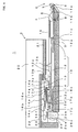
- Fig. 4 schematically shows a structure of a flatbed knitting machine 1 which is equipped with a needle selection mechanism same as that of Patent Citation 2.
- a plate-like form needle bed 2 that extends in the vertical direction with respect to this paper surface is equipped.
- grooves that are vertical to a longitudinal direction, which is an extending direction, and extends in a transverse direction on this paper are formed in regular intervals.
- a carriage 3 runs back and forth.
- a needle plate 4 is inserted.
- the needle plates are tightened by plate fixing wire 5 and fixed.
- needle beds 2 are opposed to one another with a needle bed gap 6 in between to make a pair.
- sinker plates 7 are mounted and fixed by a sinker fixing wire 8.
- a gap wire 9 is inserted.
- the needle bed 2 is disposed in front and rear of the needle bed gap 6 as viewed from the front side when the knitting machine is generally used as a mechanical device.
- Each needle bed 2 is higher on the side facing to the needle bed gap 6 and is lower as it recedes from the needle bed gap 6.
- the needle beds 2 in front and rear of the needle bed gap 6 are tilted in an inverted V shape.
- the forward and rearward direction will be described with the direction approaching the needle bed gap 6 designated as forward direction and the direction receding from the needle bed gap 6 designated as rearward direction.
- the upward and downward direction will be described with the bottom side of the needle bed 2 designated as downward direction and the surface side as upward direction.
- a needle groove is formed between adjoining needle plates 4 on the needle bed 2, a needle groove is formed.
- a knitting needle 10 is housed.
- the knitting needle 10 knits the fabric while sliding to be displaced in the horizontal direction of the drawing, that is, in the forward and rearward direction with the needle bed gap 6 used as a benchmark.
- the knitting needle 10 is configured by combining a needle 11, needle jack 12, select jack 13, and selector 14.
- the needle 11 carries out the knitting operation of the fabric by combining movement for advancing and retreating to the needle bed gap 6 side and movement for opening and closing of a front-end hook 11a by a latch 11b.
- a coupling portion 11c is provided at the position backward from the intermediate of the needle 11.
- a head end portion 12a of the needle jack 12 engages.
- a butt 12b is protruded, and the portion from the vicinity of the butt 12b to a rear end portion 12c functions as a spring that biases the butt 12b to come up in the needle groove.
- the portion between the butt 12b of the needle jack 12 and the rear end portion 12c is pressed by a head-end pressing portion 13a of the select jack 13.
- the select jack 13 receives a pressing force at a pressure-receiving butt 13b from a presser of a cam mechanism mounted to the carriage 3.
- the select jack 13 presses the needle jack 12 by the head-end pressing portion 13a, and forces down it so that the butt 12b of the needle jack 12 does not protrude from the needle groove.
- a protrusion 13c is provided at the rear position in a slight distance from the pressure receiving butt 13b of the select jack 13, a protrusion 13c is provided.
- a forked portion 13d is formed.
- the protrusion 13c is driven to advance by the selector 14.
- the side portion of the pressure-receiving butt 13b of the select jack 13 is driven to recede by the cam mechanism.
- the selector 14 has a front butt 14a, middle butt 14b, and rear butt 14c.
- the front butt 14a serves as a rocking fulcrum when the selector 14 is subjected to an action of a needle selection mechanism.
- the middle butt 14b is driven upon rearward displacement.
- the rear butt 14c is driven upon forward replacement.
- the rear side of the front butt 14a of the selector 14 is bifurcated, and the lower side is an elastic leg 14e and biases the upper side to come up.
- the middle butt 14b and the rear butt 14c are provided, and the rear end is a armature portion 14f.
- a needle pressing plate 15 To the needle plate 4, in the direction perpendicular to this paper surface, metal strips 16a, 16b, and wires 17a, 17b, and 17c are inserted.
- the needle pressing plate 15 restricts the needle 11 from above so that the needle 11 does not jump out from the needle groove.
- the metal strips 16a and 16b press the selector 14 so as that the selector 14 does not jump out from the needle groove.
- the wires 17a, 17b, and 17c function as stoppers, and the like.
- the knitting needles 10, which are disposed in a large quantity on the needle bed 2, are selected by a needle selection mechanism mounted to the carriage 3 and driven to knit by the cam mechanism.
- a needle selection mechanism mounted to the carriage 3 and driven to knit by the cam mechanism.
- a needle selecting actuator 24 is mounted by a bracket 23.
- an attraction site 25 is formed in the surface of the needle selecting actuator 24, an attraction site 25 is formed.
- the attraction site 25 faces the armature portion 14f of the selector 14.
- a plurality of magnetic poles 25a and 25b are disposed in the attraction site 25, a plurality of magnetic poles 25a and 25b are disposed.
- the actual attraction site 25 is manufactured in such a manner that a clearance between magnetic materials, to the end portion of which magnetic poles 25a and 25b are formed, is filled with synthetic resin as a non-magnetic material 25c, and after the magnetic material is firmly fixed, the surface is flattened.
- Fig. 5 shows structure of the attraction site 25 of the needle selecting actuator 24 (for example, see Patent Citation 3).
- Patent Citation 3 two controlled attraction portions which have magnetic poles 25a and 25b and the non-magnetic material 25c are disposed so as that they are sandwiched by three non-controlled attraction portions which have magnetic poles 26a, 26b, and 26c and non-magnetic materials 26d and 26e.
- To the controlled attraction portions magnetic flux generated from coils 27a and 27b as well as from a permanent magnet is supplied. It is possible to cancel magnetic flux from the permanent magnet by supplying current to the coils 27and 27b, and the controlled attraction portion can be controlled to weaken the attraction force.
- To the non-controlled attraction portion magnetic flux only from the permanent magnet is supplied.
- a presser is mounted to press the tail portion of the selector 14 from above and bring the armature portion 14f in contact with the non-controlled attraction portion to attract.
- the controlled attraction portion whether the armature portion 14f of the selector 14 is continued to be attracted or attraction is cancelled is chosen for every knitting needle 10. Consequently, in the drawing, the length of the controlled attraction portion, shown in the transverse direction, is as short as about one pitch in the placement of the knitting needle 10 and the interval between the controlled attraction portion and the non-controlled attraction portion becomes narrow, so that, if any magnetic flux from the non-controlled attraction portion leaks, the leakage flux affects the attraction cancellation control at the controlled attraction portion.
- a cam mechanism mounted to a carriage 3 works on the butt 12b of the needle jack 12 and knitting action takes place.
- a lubricant is supplied to the vicinity of the butt 12b. Since the needle bed 2 is tilted so as to be higher on the needle bed gap 6 side and lower on the needle selecting actuator 24 side, the lubricant supplied to the vicinity of the butt 12b flows down in the needle groove to the armature portion 14f of the selector 14 and the attraction site 25 of the needle selecting actuator 24.
- Patent Citation 1 has a part corresponding to the needle selecting actuator 24 mounted on the carriage 3 side, and it is assumed that the problem of attraction due to the lubricant may not occur.
- the presser that forcibly brings a portion corresponding to the armature portion 14f in contact with the attraction site 25 must be mounted on the carriage 3 side, too.
- the rocking fulcrum is provided between the portion pressed by the presser and the portion corresponding to the armature portion 14f, and therefore, the length of the member corresponding to the selector 14 in the longitudinal direction is increased and the needle selecting mechanism increases in size.
- the present invention provides a needle selecting actuator mounted to a carriage that runs along a needle bed of a flatbed knitting machine, attracting an armature portion provided to a selector of each knitting needle in order to selectively drive knitting needles placed side by side on the needle bed, and having an attraction site to which a plurality of magnetic poles are disposed including a controlled magnetic pole which can electromagnetically control attraction condition, wherein at least one groove is formed in the attraction site so as to pass through between both ends thereof in a running direction of the carriage and so as to pass by at least one magnetic pole.
- said groove is formed so as to pass by said control magnetic pole grooves are formed so as to pass the control magnetic poles.
- said attraction site has a magnetic pole formed so as to allow said groove to pass by, and also has two magnetic poles that adjoin the magnetic pole in said running direction and that are disposed with an interval provided in a width direction perpendicular to the running direction, so as to allow the groove to pass in the intervals.
- At least two said controlled magnetic poles are disposed with an interval provided in said width direction, and at least three non-controlled magnetic poles, which adjoin the two controlled magnetic poles in the running direction and conduct attraction only of said armature portion, are disposed with an interval provided in the width direction, but shifted in the width direction from the interval of the controlled magnetic poles.
- the present invention provides a flatbed knitting machine, in which front and rear needle beds are facing each other with a needle bed gap in-between, each of which is disposed tilting in such a manner that the needle beds ascend as they come close to the needle bed gap and descend as they recede from the needle bed gap, comprises:
- a needle selecting actuator is mounted to a carriage that runs along a needle bed of a flatbed knitting machine, and in an attraction site, at least one groove that pass through between both ends of the attraction site in the running direction of the carriage is formed in such a manner that it passes through at least one magnetic pole. It is assumed that providing at least one groove in the magnetic pole in this way may result in lowered attraction force, and conventionally, there existed no conception to provide at least one groove in the magnetic pole. The inventors of the present invention have found that any groove, even if the width is small enough to keep degradation of the attraction force within a permissible range, has a beneficial effect on prevention form a needle selection mistake.
- the groove passes through the surfaces of controlled magnetic poles, even if a lubricant flows down to a controlled pole, the lubricant is scraped out along the groove, adhesion of the lubricant becomes less likely to affect electromagnetic control in the attraction site, and a needle selection mistake can be prevented.
- the attraction site is provided at least with a magnetic pole on which at least one groove is formed, and with two magnetic poles, which adjoining it in the running direction, disposed with intervals in the width direction, and having at least one groove formed in the intervals.
- the groove is formed in a clearance between two magnetic poles and can prevent weakening of attraction force of two magnetic poles.
- the controlled magnetic pole it is possible for the controlled magnetic pole to prevent influence of a magnetic flux that leaks from non-controlled magnetic poles that carry out attraction only.
- a flatbed knitting machine having front and rear needle beds facing each other with a needle bed gap in-between, each of which is disposed tilting in such a manner that the needle beds ascend as they approach to the needle bed gap and descend as they recede from the needle bed gap, even when the needle selecting actuator is disposed on the lower side and a lubricant pools on the attraction site, at least one groove is provided in the attraction site, and thus a needle selection mistake can be prevented.
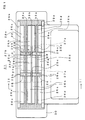
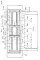
- Fig. 1 shows schematic structure of an attraction site 32 for a three-row yoke type needle selecting actuator 31 as one embodiment of the present invention.
- identical reference characters are designated to portions corresponding to a needle selecting actuator 24 shown in Fig. 4 and Fig. 5 , and similar explanation is not repeated.
- grooves 33a, 33b, and 33c are provided on the attraction site 32. Grooves 33a, 33b, and 33c are provided in such a manner that grooves extend between both ends of the attraction site 32 in the transverse direction of the drawing, in which an armature portion 14f of a selector 14 runs relative to the attraction site 32 when a carriage 3 advances and retires relative to a needle bed 2.
- a lubricant is able to be scraped out while the carriage 3 is running, and a needle selection mistake caused by adhesion of a lubricant is able to be reduced.
- the center groove 33b passes a portion of a non-magnetic material 25c between magnetic poles 25a and 25b of a controlled attraction portion. In a non-controlled attraction portion, the groove is formed to penetrate the surface of a magnetic pole 25b. Grooves 33a and 33c on both sides of the center groove 33 pass a portion of non-magnetic material 26d between magnetic poles 26a and 26b, and a portion of a non-magnetic material 26e between magnetic poles 26b and 26c, respectively, but in the controlled attraction portion, the groove is formed so as to penetrate the surfaces of magnetic poles 25a and 25b, respectively.
- a length P which magnetic poles 25a and 25b of the controlled attraction portion have in the running direction, corresponds to arrangement interval of knitting needles 10 on the needle bed 2.
- the width T which magnetic poles 25a and 25b have in the width direction perpendicular to the running direction is, for example, 3.5 mm.
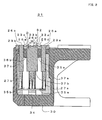
- Fig. 2 shows cross-sectional structure as viewed from a cutting surface line II-II of Fig. 1 .
- the center groove 33b is provided on the surface of the magnetic pole 26b, and therefore, it is desirable for the width to have a range that can permit weakening of attraction force of magnetic pole 26b.
- the width of the grooves 33a, 33b, and 33c affect the attraction force while the depth does not affect the attraction force.
- the grooves do not contribute to the effect of measures against oil for scraping out a lubricant.
- the cross-sectional shapes of the grooves 33a, 33b, and 33c are circular arc.
- This kind of cross-sectional shape can be obtained by holding a wire rod of circular cross section to the surface, when liquid-form synthetic resin is filled as non-magnetic materials 26d and 26e between magnetic materials, removing the wire rod after the synthetic resin solidifies, and grinding the overall attraction surface 32.
- the cross-sectional shapes of grooves 33a, 33b, and 33c may be rectangle or others which are different from circular arc, and grooves 33a, 33b, and 33c may be formed by cutting after grinding flat the attraction surface 32.
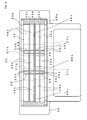
- Fig. 3 shows schematic structure of a two-row yoke type needle selecting actuator 41 as another embodiment of the present invention.
- the attraction site 42 of the needle selecting actuator 41 has three grooves 43a, 43b, and 43c, but the magnetic poles 46a and 46b of the non-controlled attraction portion are formed as end faces of a two-row yoke as is the case of the attraction site of Patent Citation 4.
- Three grooves 43a, 43b, and 43c are provided at the positions corresponding to grooves 33a, 33b, and 33c of Fig. 1 , respectively.
- Grooves 43a and 43c on both sides are formed so as to pass through the surfaces of magnetic poles 25a, 46a and 25b and 46b, but the center groove 43b is formed so as to pass through the regions of non-magnetic materials 25c and 46c and so as not to pass through the magnetic poles.
- a total of 3 grooves each, 33a, 33b, and 33c and 43a, 43b, and 43c are provided, but it is desirable to adjust the groove width and the number of grooves depending on the environment so that a needle selection mistake would be less likely to occur.
- grooves 33a and 33c pass magnetic poles 25a and 25b, respectively
- grooves 43a and 43c pass the magnetic poles 46a and 46b, respectively, but it is only necessary for at least one groove to pass the magnetic pole.
- grooves 33a, 33b, and 33c and 43a, 43b, and 43c which are horizontal to the transverse direction but inclined grooves may be provided.
- a groove is inclined, flow-down of the lubricant is facilitated and the adhering amount of the lubricant to the attraction sites 32 and 42 can be reduced.
Landscapes
- Engineering & Computer Science (AREA)
- Textile Engineering (AREA)
- Knitting Machines (AREA)
Applications Claiming Priority (2)
| Application Number | Priority Date | Filing Date | Title |
|---|---|---|---|
| JP2006320148 | 2006-11-28 | ||
| PCT/JP2007/001297 WO2008065746A1 (en) | 2006-11-28 | 2007-11-26 | Needle selecting actuator, and weft knitting machine |
Publications (3)
| Publication Number | Publication Date |
|---|---|
| EP2100991A1 true EP2100991A1 (de) | 2009-09-16 |
| EP2100991A4 EP2100991A4 (de) | 2010-12-22 |
| EP2100991B1 EP2100991B1 (de) | 2012-04-25 |
Family
ID=39467546
Family Applications (1)
| Application Number | Title | Priority Date | Filing Date |
|---|---|---|---|
| EP07828074A Not-in-force EP2100991B1 (de) | 2006-11-28 | 2007-11-26 | Nadelschloss sowie kolierstrick- oder -wirkmaschine |
Country Status (5)
| Country | Link |
|---|---|
| EP (1) | EP2100991B1 (de) |
| JP (1) | JP5161103B2 (de) |
| CN (1) | CN101578408B (de) |
| AT (1) | ATE555239T1 (de) |
| WO (1) | WO2008065746A1 (de) |
Cited By (3)
| Publication number | Priority date | Publication date | Assignee | Title |
|---|---|---|---|---|
| EP2570539A1 (de) * | 2011-09-16 | 2013-03-20 | Shima Seiki Mfg., Ltd | Nadelauswahlsystem einer Flachstrickmaschine, Selektor und Flachstrickmaschine |
| ITMI20121091A1 (it) * | 2012-06-21 | 2013-12-22 | Santoni & C Spa | Attuatore elettromagnetico, particolarmente per dispositivi di selezione degli aghi in macchine per maglieria, calzetteria o simili, ad elevata finezza. |
| CN109825942A (zh) * | 2019-01-18 | 2019-05-31 | 福建睿能科技股份有限公司 | 选针刀组件及其制备方法 |
Families Citing this family (1)
| Publication number | Priority date | Publication date | Assignee | Title |
|---|---|---|---|---|
| CN120738840B (zh) * | 2025-09-04 | 2025-11-04 | 石狮市信宝精密针筒有限公司 | 一种双面针织圆纬机 |
Family Cites Families (8)
| Publication number | Priority date | Publication date | Assignee | Title |
|---|---|---|---|---|
| JPS51102151A (de) * | 1975-03-07 | 1976-09-09 | Toyoda Automatic Loom Works | |
| DE3541171A1 (de) * | 1985-11-21 | 1987-05-27 | Stoll & Co H | Flachstrickmaschine mit nadelauswahleinrichtung |
| JPH0720503B2 (ja) | 1987-03-31 | 1995-03-08 | ホーチキ株式会社 | 火災判断装置 |
| JPH05302250A (ja) * | 1992-04-27 | 1993-11-16 | Shima Seiki Mfg Ltd | 編機用選針アクチエータ |
| US5694792A (en) | 1995-06-15 | 1997-12-09 | Shima Seiki Manufacturing, Ltd. | Needle selection device of flat knitting machine |
| JP3459514B2 (ja) * | 1995-06-15 | 2003-10-20 | 株式会社島精機製作所 | 横編機における選針装置 |
| TW521105B (en) | 2000-03-31 | 2003-02-21 | Shima Seiki Mfg | Knitting member selecting actuator of knitting machine |
| TW531579B (en) | 2000-08-28 | 2003-05-11 | Shima Seiki Mfg | A selector actuator for knitting members in a knitting machine |
-
2007
- 2007-11-26 WO PCT/JP2007/001297 patent/WO2008065746A1/ja not_active Ceased
- 2007-11-26 JP JP2008546873A patent/JP5161103B2/ja not_active Expired - Fee Related
- 2007-11-26 CN CN2007800440955A patent/CN101578408B/zh not_active Expired - Fee Related
- 2007-11-26 EP EP07828074A patent/EP2100991B1/de not_active Not-in-force
- 2007-11-26 AT AT07828074T patent/ATE555239T1/de active
Cited By (6)
| Publication number | Priority date | Publication date | Assignee | Title |
|---|---|---|---|---|
| EP2570539A1 (de) * | 2011-09-16 | 2013-03-20 | Shima Seiki Mfg., Ltd | Nadelauswahlsystem einer Flachstrickmaschine, Selektor und Flachstrickmaschine |
| KR101387965B1 (ko) * | 2011-09-16 | 2014-04-22 | 가부시키가이샤 시마세이키 세이사쿠쇼 | 횡편기의 선침 시스템, 실렉터 및 횡편기 |
| ITMI20121091A1 (it) * | 2012-06-21 | 2013-12-22 | Santoni & C Spa | Attuatore elettromagnetico, particolarmente per dispositivi di selezione degli aghi in macchine per maglieria, calzetteria o simili, ad elevata finezza. |
| WO2013189797A1 (en) * | 2012-06-21 | 2013-12-27 | Santoni S.P.A. | Electromagnetic actuator, particularly for needle selection devices in machines for knitting, hosiery or the like, with high gauge |
| US9328439B2 (en) | 2012-06-21 | 2016-05-03 | Santoni S.P.A. | Electromagnetic actuator, particularly for needle selection devices in machines for knitting, hosiery or the like, with high gauge |
| CN109825942A (zh) * | 2019-01-18 | 2019-05-31 | 福建睿能科技股份有限公司 | 选针刀组件及其制备方法 |
Also Published As
| Publication number | Publication date |
|---|---|
| WO2008065746A1 (en) | 2008-06-05 |
| CN101578408A (zh) | 2009-11-11 |
| JPWO2008065746A1 (ja) | 2010-03-04 |
| EP2100991B1 (de) | 2012-04-25 |
| JP5161103B2 (ja) | 2013-03-13 |
| ATE555239T1 (de) | 2012-05-15 |
| CN101578408B (zh) | 2011-08-17 |
| EP2100991A4 (de) | 2010-12-22 |
Similar Documents
| Publication | Publication Date | Title |
|---|---|---|
| EP2100991B1 (de) | Nadelschloss sowie kolierstrick- oder -wirkmaschine | |
| EP1026299B1 (de) | Nadelauswahlvorrichtung für eine Flachstrickmaschine | |
| KR100947186B1 (ko) | 터프팅 기계용 파지기 | |
| EP2196569A1 (de) | Flachstrickmaschine | |
| KR101387965B1 (ko) | 횡편기의 선침 시스템, 실렉터 및 횡편기 | |
| EP2474654B1 (de) | Nadelauswahlvorrichtung für eine flachstrickmaschine und selektor dafür | |
| US6584810B2 (en) | Knitting member selecting actuator of knitting machine | |
| EP0690161B1 (de) | Mustervorrichtung für eine kettenwirkmaschine | |
| US6968715B2 (en) | Magnetic needle selecting device of weft knitting machine | |
| US7213422B2 (en) | Needle selection device for weft knitting machine | |
| US4282724A (en) | Control magnet system | |
| EP2372003B1 (de) | Nockenvorrichtung für transferaufnahmenadel | |
| KR101356444B1 (ko) | 횡편기 | |
| EP2415917B1 (de) | Schiebernadel für Flachstrickmaschinen | |
| CN102234873B (zh) | 选针沉降片 | |
| TWI582287B (zh) | 刺繡機及其操作方法 | |
| CN119777063B (zh) | 横机 | |
| CN115142183B (zh) | 横机的选针装置及方法 | |
| CN101629355A (zh) | 一种织针组合 | |
| EP1357210A1 (de) | Nadelselektor für jacquardmaschine | |
| CN121183499A (zh) | 一种提花选针装置 | |
| KR20100099682A (ko) | 언더니들 선택장치 | |
| CN101200838A (zh) | 针织横编机压纱机构的沉降片片踵导引块自驱动装置 | |
| CN102105628A (zh) | 编织针驱动用三角及横编机 | |
| KR20210014156A (ko) | 편직 요소 이동을 제동하기 위한 브레이크 요소, 편직 요소, 편직 요소 캐리어, 편직 장치 및 편직 장치를 위한 모듈식 시스템 |
Legal Events
| Date | Code | Title | Description |
|---|---|---|---|
| PUAI | Public reference made under article 153(3) epc to a published international application that has entered the european phase |
Free format text: ORIGINAL CODE: 0009012 |
|
| 17P | Request for examination filed |
Effective date: 20090619 |
|
| AK | Designated contracting states |
Kind code of ref document: A1 Designated state(s): AT BE BG CH CY CZ DE DK EE ES FI FR GB GR HU IE IS IT LI LT LU LV MC MT NL PL PT RO SE SI SK TR |
|
| DAX | Request for extension of the european patent (deleted) | ||
| A4 | Supplementary search report drawn up and despatched |
Effective date: 20101118 |
|
| REG | Reference to a national code |
Ref country code: DE Ref legal event code: R079 Ref document number: 602007022307 Country of ref document: DE Free format text: PREVIOUS MAIN CLASS: D04B0015820000 Ipc: D04B0015780000 |
|
| GRAP | Despatch of communication of intention to grant a patent |
Free format text: ORIGINAL CODE: EPIDOSNIGR1 |
|
| RIC1 | Information provided on ipc code assigned before grant |
Ipc: D04B 35/28 20060101ALI20110819BHEP Ipc: D04B 15/82 20060101ALI20110819BHEP Ipc: D04B 15/78 20060101AFI20110819BHEP |
|
| GRAS | Grant fee paid |
Free format text: ORIGINAL CODE: EPIDOSNIGR3 |
|
| GRAA | (expected) grant |
Free format text: ORIGINAL CODE: 0009210 |
|
| AK | Designated contracting states |
Kind code of ref document: B1 Designated state(s): AT BE BG CH CY CZ DE DK EE ES FI FR GB GR HU IE IS IT LI LT LU LV MC MT NL PL PT RO SE SI SK TR |
|
| REG | Reference to a national code |
Ref country code: GB Ref legal event code: FG4D |
|
| REG | Reference to a national code |
Ref country code: CH Ref legal event code: EP |
|
| REG | Reference to a national code |
Ref country code: AT Ref legal event code: REF Ref document number: 555239 Country of ref document: AT Kind code of ref document: T Effective date: 20120515 |
|
| REG | Reference to a national code |
Ref country code: IE Ref legal event code: FG4D |
|
| REG | Reference to a national code |
Ref country code: DE Ref legal event code: R096 Ref document number: 602007022307 Country of ref document: DE Effective date: 20120621 |
|
| REG | Reference to a national code |
Ref country code: NL Ref legal event code: VDEP Effective date: 20120425 |
|
| REG | Reference to a national code |
Ref country code: AT Ref legal event code: MK05 Ref document number: 555239 Country of ref document: AT Kind code of ref document: T Effective date: 20120425 |
|
| LTIE | Lt: invalidation of european patent or patent extension |
Effective date: 20120425 |
|
| PG25 | Lapsed in a contracting state [announced via postgrant information from national office to epo] |
Ref country code: PL Free format text: LAPSE BECAUSE OF FAILURE TO SUBMIT A TRANSLATION OF THE DESCRIPTION OR TO PAY THE FEE WITHIN THE PRESCRIBED TIME-LIMIT Effective date: 20120425 Ref country code: SE Free format text: LAPSE BECAUSE OF FAILURE TO SUBMIT A TRANSLATION OF THE DESCRIPTION OR TO PAY THE FEE WITHIN THE PRESCRIBED TIME-LIMIT Effective date: 20120425 Ref country code: CY Free format text: LAPSE BECAUSE OF FAILURE TO SUBMIT A TRANSLATION OF THE DESCRIPTION OR TO PAY THE FEE WITHIN THE PRESCRIBED TIME-LIMIT Effective date: 20120425 Ref country code: FI Free format text: LAPSE BECAUSE OF FAILURE TO SUBMIT A TRANSLATION OF THE DESCRIPTION OR TO PAY THE FEE WITHIN THE PRESCRIBED TIME-LIMIT Effective date: 20120425 Ref country code: LT Free format text: LAPSE BECAUSE OF FAILURE TO SUBMIT A TRANSLATION OF THE DESCRIPTION OR TO PAY THE FEE WITHIN THE PRESCRIBED TIME-LIMIT Effective date: 20120425 Ref country code: IS Free format text: LAPSE BECAUSE OF FAILURE TO SUBMIT A TRANSLATION OF THE DESCRIPTION OR TO PAY THE FEE WITHIN THE PRESCRIBED TIME-LIMIT Effective date: 20120825 |
|
| PG25 | Lapsed in a contracting state [announced via postgrant information from national office to epo] |
Ref country code: GR Free format text: LAPSE BECAUSE OF FAILURE TO SUBMIT A TRANSLATION OF THE DESCRIPTION OR TO PAY THE FEE WITHIN THE PRESCRIBED TIME-LIMIT Effective date: 20120726 Ref country code: PT Free format text: LAPSE BECAUSE OF FAILURE TO SUBMIT A TRANSLATION OF THE DESCRIPTION OR TO PAY THE FEE WITHIN THE PRESCRIBED TIME-LIMIT Effective date: 20120827 Ref country code: SI Free format text: LAPSE BECAUSE OF FAILURE TO SUBMIT A TRANSLATION OF THE DESCRIPTION OR TO PAY THE FEE WITHIN THE PRESCRIBED TIME-LIMIT Effective date: 20120425 Ref country code: LV Free format text: LAPSE BECAUSE OF FAILURE TO SUBMIT A TRANSLATION OF THE DESCRIPTION OR TO PAY THE FEE WITHIN THE PRESCRIBED TIME-LIMIT Effective date: 20120425 |
|
| PG25 | Lapsed in a contracting state [announced via postgrant information from national office to epo] |
Ref country code: BE Free format text: LAPSE BECAUSE OF FAILURE TO SUBMIT A TRANSLATION OF THE DESCRIPTION OR TO PAY THE FEE WITHIN THE PRESCRIBED TIME-LIMIT Effective date: 20120425 |
|
| PG25 | Lapsed in a contracting state [announced via postgrant information from national office to epo] |
Ref country code: RO Free format text: LAPSE BECAUSE OF FAILURE TO SUBMIT A TRANSLATION OF THE DESCRIPTION OR TO PAY THE FEE WITHIN THE PRESCRIBED TIME-LIMIT Effective date: 20120425 Ref country code: EE Free format text: LAPSE BECAUSE OF FAILURE TO SUBMIT A TRANSLATION OF THE DESCRIPTION OR TO PAY THE FEE WITHIN THE PRESCRIBED TIME-LIMIT Effective date: 20120425 Ref country code: DK Free format text: LAPSE BECAUSE OF FAILURE TO SUBMIT A TRANSLATION OF THE DESCRIPTION OR TO PAY THE FEE WITHIN THE PRESCRIBED TIME-LIMIT Effective date: 20120425 Ref country code: NL Free format text: LAPSE BECAUSE OF FAILURE TO SUBMIT A TRANSLATION OF THE DESCRIPTION OR TO PAY THE FEE WITHIN THE PRESCRIBED TIME-LIMIT Effective date: 20120425 Ref country code: AT Free format text: LAPSE BECAUSE OF FAILURE TO SUBMIT A TRANSLATION OF THE DESCRIPTION OR TO PAY THE FEE WITHIN THE PRESCRIBED TIME-LIMIT Effective date: 20120425 Ref country code: SK Free format text: LAPSE BECAUSE OF FAILURE TO SUBMIT A TRANSLATION OF THE DESCRIPTION OR TO PAY THE FEE WITHIN THE PRESCRIBED TIME-LIMIT Effective date: 20120425 Ref country code: CZ Free format text: LAPSE BECAUSE OF FAILURE TO SUBMIT A TRANSLATION OF THE DESCRIPTION OR TO PAY THE FEE WITHIN THE PRESCRIBED TIME-LIMIT Effective date: 20120425 |
|
| PLBE | No opposition filed within time limit |
Free format text: ORIGINAL CODE: 0009261 |
|
| STAA | Information on the status of an ep patent application or granted ep patent |
Free format text: STATUS: NO OPPOSITION FILED WITHIN TIME LIMIT |
|
| 26N | No opposition filed |
Effective date: 20130128 |
|
| PG25 | Lapsed in a contracting state [announced via postgrant information from national office to epo] |
Ref country code: ES Free format text: LAPSE BECAUSE OF FAILURE TO SUBMIT A TRANSLATION OF THE DESCRIPTION OR TO PAY THE FEE WITHIN THE PRESCRIBED TIME-LIMIT Effective date: 20120805 |
|
| REG | Reference to a national code |
Ref country code: DE Ref legal event code: R097 Ref document number: 602007022307 Country of ref document: DE Effective date: 20130128 |
|
| REG | Reference to a national code |
Ref country code: CH Ref legal event code: PL |
|
| GBPC | Gb: european patent ceased through non-payment of renewal fee |
Effective date: 20121126 |
|
| PG25 | Lapsed in a contracting state [announced via postgrant information from national office to epo] |
Ref country code: BG Free format text: LAPSE BECAUSE OF FAILURE TO SUBMIT A TRANSLATION OF THE DESCRIPTION OR TO PAY THE FEE WITHIN THE PRESCRIBED TIME-LIMIT Effective date: 20120725 Ref country code: CH Free format text: LAPSE BECAUSE OF NON-PAYMENT OF DUE FEES Effective date: 20121130 Ref country code: LI Free format text: LAPSE BECAUSE OF NON-PAYMENT OF DUE FEES Effective date: 20121130 |
|
| REG | Reference to a national code |
Ref country code: FR Ref legal event code: ST Effective date: 20130731 |
|
| REG | Reference to a national code |
Ref country code: IE Ref legal event code: MM4A |
|
| PG25 | Lapsed in a contracting state [announced via postgrant information from national office to epo] |
Ref country code: IE Free format text: LAPSE BECAUSE OF NON-PAYMENT OF DUE FEES Effective date: 20121126 |
|
| PG25 | Lapsed in a contracting state [announced via postgrant information from national office to epo] |
Ref country code: MT Free format text: LAPSE BECAUSE OF FAILURE TO SUBMIT A TRANSLATION OF THE DESCRIPTION OR TO PAY THE FEE WITHIN THE PRESCRIBED TIME-LIMIT Effective date: 20120425 Ref country code: GB Free format text: LAPSE BECAUSE OF NON-PAYMENT OF DUE FEES Effective date: 20121126 Ref country code: FR Free format text: LAPSE BECAUSE OF NON-PAYMENT OF DUE FEES Effective date: 20121130 |
|
| PG25 | Lapsed in a contracting state [announced via postgrant information from national office to epo] |
Ref country code: TR Free format text: LAPSE BECAUSE OF FAILURE TO SUBMIT A TRANSLATION OF THE DESCRIPTION OR TO PAY THE FEE WITHIN THE PRESCRIBED TIME-LIMIT Effective date: 20120425 Ref country code: MC Free format text: LAPSE BECAUSE OF NON-PAYMENT OF DUE FEES Effective date: 20121130 |
|
| PG25 | Lapsed in a contracting state [announced via postgrant information from national office to epo] |
Ref country code: LU Free format text: LAPSE BECAUSE OF NON-PAYMENT OF DUE FEES Effective date: 20121126 |
|
| PG25 | Lapsed in a contracting state [announced via postgrant information from national office to epo] |
Ref country code: HU Free format text: LAPSE BECAUSE OF FAILURE TO SUBMIT A TRANSLATION OF THE DESCRIPTION OR TO PAY THE FEE WITHIN THE PRESCRIBED TIME-LIMIT Effective date: 20071126 |
|
| PGFP | Annual fee paid to national office [announced via postgrant information from national office to epo] |
Ref country code: IT Payment date: 20221011 Year of fee payment: 16 Ref country code: DE Payment date: 20221004 Year of fee payment: 16 |
|
| REG | Reference to a national code |
Ref country code: DE Ref legal event code: R119 Ref document number: 602007022307 Country of ref document: DE |
|
| PG25 | Lapsed in a contracting state [announced via postgrant information from national office to epo] |
Ref country code: DE Free format text: LAPSE BECAUSE OF NON-PAYMENT OF DUE FEES Effective date: 20240601 |
|
| PG25 | Lapsed in a contracting state [announced via postgrant information from national office to epo] |
Ref country code: DE Free format text: LAPSE BECAUSE OF NON-PAYMENT OF DUE FEES Effective date: 20240601 |
|
| PG25 | Lapsed in a contracting state [announced via postgrant information from national office to epo] |
Ref country code: IT Free format text: LAPSE BECAUSE OF NON-PAYMENT OF DUE FEES Effective date: 20231126 |
|
| PG25 | Lapsed in a contracting state [announced via postgrant information from national office to epo] |
Ref country code: IT Free format text: LAPSE BECAUSE OF NON-PAYMENT OF DUE FEES Effective date: 20231126 |