EP2101037B1 - Verfahren zum Reduzieren von Restspannung in einem Rollenmeissel - Google Patents
Verfahren zum Reduzieren von Restspannung in einem Rollenmeissel Download PDFInfo
- Publication number
- EP2101037B1 EP2101037B1 EP09007820A EP09007820A EP2101037B1 EP 2101037 B1 EP2101037 B1 EP 2101037B1 EP 09007820 A EP09007820 A EP 09007820A EP 09007820 A EP09007820 A EP 09007820A EP 2101037 B1 EP2101037 B1 EP 2101037B1
- Authority
- EP
- European Patent Office
- Prior art keywords
- ball
- weld
- head
- roller cone
- cone bit
- Prior art date
- Legal status (The legal status is an assumption and is not a legal conclusion. Google has not performed a legal analysis and makes no representation as to the accuracy of the status listed.)
- Active
Links
Images

Classifications
-
- E—FIXED CONSTRUCTIONS
- E21—EARTH OR ROCK DRILLING; MINING
- E21B—EARTH OR ROCK DRILLING; OBTAINING OIL, GAS, WATER, SOLUBLE OR MELTABLE MATERIALS OR A SLURRY OF MINERALS FROM WELLS
- E21B10/00—Drill bits
- E21B10/08—Roller bits
- E21B10/20—Roller bits characterised by detachable or adjustable parts, e.g. legs or axles
-
- E—FIXED CONSTRUCTIONS
- E21—EARTH OR ROCK DRILLING; MINING
- E21B—EARTH OR ROCK DRILLING; OBTAINING OIL, GAS, WATER, SOLUBLE OR MELTABLE MATERIALS OR A SLURRY OF MINERALS FROM WELLS
- E21B10/00—Drill bits
- E21B10/08—Roller bits
-
- E—FIXED CONSTRUCTIONS
- E21—EARTH OR ROCK DRILLING; MINING
- E21B—EARTH OR ROCK DRILLING; OBTAINING OIL, GAS, WATER, SOLUBLE OR MELTABLE MATERIALS OR A SLURRY OF MINERALS FROM WELLS
- E21B10/00—Drill bits
- E21B10/08—Roller bits
- E21B10/22—Roller bits characterised by bearing, lubrication or sealing details
Definitions
- the present invention relates in general to stress reduction in roller cone bits and, in particular, to an improved method, and apparatus for reducing residual stress in as-welded roller cone bit ball plug welds.
- Rotary-type drill bits include both rotary drag bits and roller-cone bits.
- the bit typically has three cones, each independently rotatable with respect to the bit body supporting the cones through bearing assemblies.
- the cones carry either integrally formed teeth or separately formed inserts that provide the cutting action of the bit.
- Roller cone bits typically use a ball retention system for securing the cones to the heads.
- the retention system includes a radial ball race incorporated into each cone and the head bearings.
- a ball way is provided between the head ball race and the head outer diameter (OD) to facilitate assembly.
- the respective ball races are aligned and, together, they define a toroidal space.
- Ball bearings are introduced via the ball way into the space.
- a ball plug is then inserted into the ball way to block the discontinuity (i.e., the hole) in the head ball race and to ensure that the ball bearings are retained in the race.
- the ball plug is secured to the head OD by welding.
- US 3,989,315 discloses a roller-cone bit wherein the ball plug is secured to the head outer diameter with a mechanically wedged plug.
- WO 99/39075 discloses a roller-cone bit wherein the ball plug weld is formed at least in part by a layer of hard facing material.
- One embodiment of a method, and apparatus of the present invention describes a solution for reducing residual stress in the region of as-welded ball plug welds. By reducing weld area residual stress with the present invention, service load capacity and/or service life is increased.
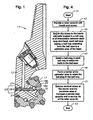
- Bit 11 comprises a bit body 13 having heads 15 (one shown) with cones 17.
- Each head 15 and cone 17 includes a retention system having a ball race 19 at an intersection between the head 15 and cone 17.
- a ball way 21 extends from the ball race 19 to an outer diameter (left sides of Figures 1 and 2 ) of the head 15.
- the outer diameter forms a portion of a perimeter area 23 of the head 15.
- the perimeter area 23 generally includes a region of the head 15 extending from the ball way 21 radially outward and axially inward with respect to the ball way 21.
- the respective ball races 19a, 19b of the head 15 and cone 17 are aligned to define a toroidal space.
- Balls 25 are located in the ball race 19 for mechanically retaining the cone 17 on the head 15.
- a ball plug 27 is located in the ball way 21 to retain the balls 25 in the ball race 19.
- a barrier 29, such as a weld, is formed adjacent the outer diameter of the head 15 to secure the ball plug 27 in the ball way 21.
- the present invention also comprises stress reduction means for reducing residual stress at the barrier (e.g., weld) 29 and the perimeter area 23 of the head 15 adjacent the outer diameter to increase a service load capacity and a service life of the roller cone bit 11.
- the stress reduction means comprises an inner weld 31 ( Figure 2 ) formed from a first material adjacent the ball plug 27.
- the weld29 is formed on the inner weld 31 from a second material that has a higher strength than the first material.
- the first material may comprise many different materials, including nickel, nickel alloy, stainless steel, and inconel.
- the second material may comprise steel or the like.
- a single weld comprising one or more passes may be used as the barrier 29.
- a single material, such as nickel, is utilized to form the welds.
- the entire weld may be formed from a single, softer material.
- the stress reduction means comprises a void 39 ( Figure 3 ) in the barrier 29.
- the void 39 may comprise a drilled hole that extends in an axial direction of the ball way 21.
- a system for reducing residual stress in a roller cone bit 11 comprises the elements described above, including the retention system for securing the cones 17 to the heads 15.
- a residual stress reduction is located at the barrier 29 and the perimeter area 23 to increase a service load capacity and a service life of the roller cone bit 11.
- the residual stress reduction may comprise an inner weld 31 formed adjacent the ball plug 27 from a first material, and the barrier 29 may comprise an outer weld formed on the inner weld 31 from a second material that has a higher strength than the first material.
- the residual stress reduction also may comprise a heat treatment that may be performed on the entire roller cone bit 11.
- the residual stress reduction may be localized and limited to the barrier 29 and the perimeter area 23, as with a small device 35 (e.g., a heat source, an ultrasonic tool, etc.) and a controller 37 for applying a heat treatment or an ultrasonic vibration treatment, respectively, to the barrier 29 and the perimeter area 23.
- the residual stress reduction may be accomplished by removing material from the barrier 29, such as by forming a hole 39 in the barrier 29 that extends in an axial direction with respect to the ball way 21.
- the present invention also comprises a method of reducing residual stress in a roller cone bit.
- one embodiment of the method starts as indicated at step 41, and comprises providing a roller cone bit with heads with cones (step 43); securing the cones to the heads with balls located in a ball race at an intersection between each cone and head, each ball race having a ball way extending from the ball race to a perimeter area of the head (step 45); installing a ball plug in each ball way to retain the balls in the ball race (step 47); forming a barrier at the perimeter area to retain the ball plug in the ball way (step 49); reducing residual stress at the barrier and the perimeter area to increase a service load capacity and a service life of the roller cone bit (step 51); before ending as indicated at step 53.
- the method also may comprise forming an inner weld from a first material adjacent the ball plug, and forming an outer weld on the inner weld from a second material that has a higher strength than the first material.
- Step 51 may comprise applying a heat treatment, such as by subjecting the ball plug to elevated temperatures during the stress relief operation. This embodiment may further comprise localizing the heat treatment to a limited portion of the roller cone bit including the barrier and the perimeter area, or subjecting the entire roller cone bit to the heat treatment.
- Step 51 also may comprise applying an ultrasonic vibration treatment the barrier and the perimeter area, or removing material from the barrier, such as by forming a hole in the barrier that extends in an axial direction of the ball way.
Landscapes
- Engineering & Computer Science (AREA)
- Geology (AREA)
- Life Sciences & Earth Sciences (AREA)
- Mining & Mineral Resources (AREA)
- Physics & Mathematics (AREA)
- Environmental & Geological Engineering (AREA)
- Fluid Mechanics (AREA)
- Mechanical Engineering (AREA)
- General Life Sciences & Earth Sciences (AREA)
- Geochemistry & Mineralogy (AREA)
- Heat Treatment Of Articles (AREA)
- Rolling Contact Bearings (AREA)
- Percussive Tools And Related Accessories (AREA)
- Earth Drilling (AREA)
Claims (13)
- Verfahren zum Verringern der Restbeanspruchung in einem Rollenmeißel, wobei das Verfahren Folgendes umfasst:(a) Vorsehen eines Rollenmeißels (11) mit Köpfen (15) mit Konussen (17);(b) Befestigen der Konusse (17) an den Köpfen (15) mit Kugeln (25), die sich in einer Kugellaufbahn (19) an einer Schnittfläche zwischen jedem Konus und
dem Kopf befinden, wobei jede Kugellaufbahn (19) eine Kugelbahn (21) besitzt, die von der Kugellaufbahn zu einem Umfangsbereich (23) des Kopfes (15) verläuft;(c) Installieren eines Kugelstopfens (27) in jeder Kugelbahn (21), um die Kugeln (25) in der Kugellaufbahn (19) zu halten; und(d) Bilden einer Sperre (29) in dem Umfangsbereich (23), um den Kugelstopfen (27) in der Kugelbahn (21) zu halten, indem eine Schweißnaht gebildet wird;dadurch gekennzeichnet, dass die Schweißnaht aus einem einzigen Material gebildet wird, das aus der Gruppe gewählt wird, die besteht aus: (i) Edelstahl; und (ii) Inconel. - Verfahren nach Anspruch 1, wobei die Schweißnaht (29) aus Inconel gebildet wird.
- Verfahren nach Anspruch 1 oder 2, wobei die Schweißnaht (29) eine einzige Schweißnaht umfasst.
- Verfahren nach Anspruch 3, wobei das Bilden der einzigen Schweißnaht (29) in wenigstens einem Durchgang aus dem einzigen Material gebildet wird.
- Verfahren nach einem vorhergehenden Anspruch, das ferner das Anwenden einer Beanspruchungsentlastungsoperation mit Wärmebehandlung umfasst, um die Restbeanspruchung in der Sperre (29) und dem Umfangsbereich (23) des Rollenmeißels (11) zu verringern.
- Verfahren nach Anspruch 5, das das Beaufschlagen des Kugelstopfens (27) mit erhöhten Temperaturen während der Beanspruchungsentlastungsoperation umfasst.
- Verfahren nach Anspruch 5, das das räumliche Einschränken der Wärmebehandlung auf einen begrenzten Abschnitt des Rollenmeißels (11), der die Sperre (29) und den Umfangsbereich (23) enthält, umfasst.
- Verfahren nach Anspruch 5, das das Beaufschlagen des gesamten Rollenmeißels (11) mit der Wärmebehandlung umfasst.
- Verfahren nach einem der Ansprüche 1 bis 4, das ferner das Anwenden einer Ultraschallvibrationsbehandlung auf die Sperre (29) und den Umfangsbereich (23) umfasst, um die Restbeanspruchung in der Sperre (29) und dem Umfangsbereich (23) des Rollenmeißels (11) zu verringern.
- Verfahren nach einem vorhergehenden Anspruch, wobei die Restbeanspruchung in der Sperre (29) und dem Umfangsbereich (23) verringert wird, um eine Arbeitslastkapazität und eine Arbeitslebensdauer des Rollenmeißels (11) zu erhöhen.
- Rollenmeißel, der Folgendes umfasst:einen Meißelkörper (13), der Köpfe (15) mit Konussen (17) besitzt, wobei jeder Kopf und jeder Konus an einer Schnittfläche zwischen dem Kopf (15) und dem Konus (17) eine Kugellaufbahn (19) enthalten;eine Kugelbahn (21), die von der Kugellaufbahn (19) zu einem äußeren Durchmesser des Kopfes (15) verläuft, wobei die jeweiligen Kugellaufbahnen des Kopfes und des Konus aufeinander ausgerichtet sind, um einen toroidförmigen Raum zu definieren;Kugeln (25), die sich in der Kugellaufbahn (19) befinden, um den Konus (15) an dem Kopf (17) mechanisch zu halten;einen Kugelstopfen (27), der sich in der Kugelbahn (21) befindet, um die Kugeln (25) in der Kugellaufbahn (19) zu halten; undeine Schweißnaht (29), die in der Nähe des äußeren Durchmessers des Kopfes (15) gebildet ist, um den Kugelstopfen (27) in der Kugelbahn (21) zu befestigen;dadurch gekennzeichnet, dass die Schweißnaht (29) aus einem einzigen Material gebildet ist, das aus der Gruppe gewählt ist, die besteht aus: (i) Edelstahl; und (ii) Inconel.
- Rollenmeißel nach Anspruch 11, wobei die Schweißnaht (29) aus Inconel gebildet ist.
- Rollenmeißel nach Anspruch 11 oder 12, wobei die Schweißnaht (29) eine einzige Schweißnaht umfasst.
Applications Claiming Priority (2)
| Application Number | Priority Date | Filing Date | Title |
|---|---|---|---|
| US11/183,121 US20070014495A1 (en) | 2005-07-15 | 2005-07-15 | System, method, and apparatus for reducing residual stress in as-welded roller cone bit ball plug welds |
| EP06787231A EP1904713B1 (de) | 2005-07-15 | 2006-07-14 | System, verfahren und vorrichtung zur reduzierung von restspannungen in rollenbohrmeisselkugelstopfenschweissungen im geschweissten zustand |
Related Parent Applications (2)
| Application Number | Title | Priority Date | Filing Date |
|---|---|---|---|
| EP06787231A Division EP1904713B1 (de) | 2005-07-15 | 2006-07-14 | System, verfahren und vorrichtung zur reduzierung von restspannungen in rollenbohrmeisselkugelstopfenschweissungen im geschweissten zustand |
| EP06787231.7 Division | 2006-07-14 |
Publications (2)
| Publication Number | Publication Date |
|---|---|
| EP2101037A1 EP2101037A1 (de) | 2009-09-16 |
| EP2101037B1 true EP2101037B1 (de) | 2012-12-05 |
Family
ID=37103099
Family Applications (4)
| Application Number | Title | Priority Date | Filing Date |
|---|---|---|---|
| EP09007821A Withdrawn EP2101038A1 (de) | 2005-07-15 | 2006-07-14 | Verfahren zum Reduzieren von Restspannung in einem Rollenmeissel |
| EP09007819A Active EP2101036B1 (de) | 2005-07-15 | 2006-07-14 | Verfahren zum Reduzieren von Restspannung in einem Rollenmeissel |
| EP09007820A Active EP2101037B1 (de) | 2005-07-15 | 2006-07-14 | Verfahren zum Reduzieren von Restspannung in einem Rollenmeissel |
| EP06787231A Active EP1904713B1 (de) | 2005-07-15 | 2006-07-14 | System, verfahren und vorrichtung zur reduzierung von restspannungen in rollenbohrmeisselkugelstopfenschweissungen im geschweissten zustand |
Family Applications Before (2)
| Application Number | Title | Priority Date | Filing Date |
|---|---|---|---|
| EP09007821A Withdrawn EP2101038A1 (de) | 2005-07-15 | 2006-07-14 | Verfahren zum Reduzieren von Restspannung in einem Rollenmeissel |
| EP09007819A Active EP2101036B1 (de) | 2005-07-15 | 2006-07-14 | Verfahren zum Reduzieren von Restspannung in einem Rollenmeissel |
Family Applications After (1)
| Application Number | Title | Priority Date | Filing Date |
|---|---|---|---|
| EP06787231A Active EP1904713B1 (de) | 2005-07-15 | 2006-07-14 | System, verfahren und vorrichtung zur reduzierung von restspannungen in rollenbohrmeisselkugelstopfenschweissungen im geschweissten zustand |
Country Status (6)
| Country | Link |
|---|---|
| US (1) | US20070014495A1 (de) |
| EP (4) | EP2101038A1 (de) |
| CN (1) | CN101384791A (de) |
| AT (1) | ATE532939T1 (de) |
| RU (1) | RU2008105366A (de) |
| WO (1) | WO2007011686A1 (de) |
Families Citing this family (6)
| Publication number | Priority date | Publication date | Assignee | Title |
|---|---|---|---|---|
| US20080006447A1 (en) * | 2006-07-07 | 2008-01-10 | Walter Scott Dillard | Roller cone drill bit that includes components with planar reference surfaces for gauging and inspection |
| US20100252331A1 (en) * | 2009-04-01 | 2010-10-07 | High Angela D | Methods for forming boring shoes for wellbore casing, and boring shoes and intermediate structures formed by such methods |
| JP5524005B2 (ja) | 2010-09-24 | 2014-06-18 | 三菱重工業株式会社 | 溶接ビード切削装置および蒸気タービンのラジアルピン抜取方法 |
| CN103678926A (zh) * | 2013-12-23 | 2014-03-26 | 吉林大学 | 提高焊接仿真位移解精度的快速自适应高温截断优化方法 |
| CN110527936B (zh) * | 2019-09-24 | 2020-11-10 | 北京理工大学 | 阵列式高能弹性波消减及均化构件残余应力装置及方法 |
| CN114295260B (zh) * | 2021-12-29 | 2024-03-26 | 福建省锅炉压力容器检验研究院 | 一种焊缝残余应力可靠性模拟测试装置 |
Family Cites Families (22)
| Publication number | Priority date | Publication date | Assignee | Title |
|---|---|---|---|---|
| US1983283A (en) * | 1933-09-16 | 1934-12-04 | Hughes Tool Co | Bearing for drill cutters |
| US2283312A (en) * | 1941-03-06 | 1942-05-19 | Reed Roller Bit Co | Rock bit |
| US2339161A (en) * | 1942-07-21 | 1944-01-11 | Reed Roller Bit Co | Cone bit construction |
| US3158214A (en) * | 1962-03-15 | 1964-11-24 | Hughes Tool Co | Shirttail hardfacing |
| US3624345A (en) * | 1968-10-31 | 1971-11-30 | Babcock & Wilcox Co | Arc welding electrode arrangements |
| US3601456A (en) * | 1970-03-23 | 1971-08-24 | Myron D Becker | Antiskew device for drill bit bearings |
| US3664379A (en) * | 1970-06-02 | 1972-05-23 | Chicago Bridge & Iron Co | Multiple-layer vessel with crack arresting welded joint |
| US3719241A (en) * | 1971-11-24 | 1973-03-06 | Dresser Ind | Free breathing lubrication system for sealed bearing rock bits |
| US3917361A (en) * | 1974-01-30 | 1975-11-04 | Reed Tool Co | Friction bearing |
| US3989315A (en) * | 1975-08-14 | 1976-11-02 | Reed Tool Company | Drill bit |
| SE397781B (sv) * | 1976-03-04 | 1977-11-21 | Stal Laval Turbin Ab | Sett att framstella en rorledning |
| SE7703810L (sv) * | 1977-04-01 | 1978-10-02 | Sandvik Ab | Tetningsanordning vid rullborrkronor |
| US4183416A (en) * | 1978-08-18 | 1980-01-15 | Dresser Industries, Inc. | Cutter actuated rock bit lubrication system |
| US4280571A (en) * | 1980-01-24 | 1981-07-28 | Dresser Industries, Inc. | Rock bit |
| US4330158A (en) * | 1980-10-09 | 1982-05-18 | Dresser Industries, Inc. | Rotary rock bit with improved thrust flange |
| US4641976A (en) * | 1984-02-09 | 1987-02-10 | Smith International, Inc. | Copper-based spinodal alloy bearings |
| CA2009987A1 (en) * | 1990-02-14 | 1991-08-14 | Kenneth M. White | Journal bearing type rock bit |
| US5452771A (en) * | 1994-03-31 | 1995-09-26 | Dresser Industries, Inc. | Rotary drill bit with improved cutter and seal protection |
| US5570750A (en) * | 1995-04-20 | 1996-11-05 | Dresser Industries, Inc. | Rotary drill bit with improved shirttail and seal protection |
| JPH11209825A (ja) * | 1998-01-23 | 1999-08-03 | Toshiba Corp | 溶接後熱処理装置 |
| WO1999039075A1 (en) * | 1998-01-30 | 1999-08-05 | Dresser Industries, Inc. | Rotary cone drill bit having a ball plug weld with hardfacing |
| US6993948B2 (en) * | 2003-06-13 | 2006-02-07 | General Electric Company | Methods for altering residual stresses using mechanically induced liquid cavitation |
-
2005
- 2005-07-15 US US11/183,121 patent/US20070014495A1/en not_active Abandoned
-
2006
- 2006-07-14 AT AT09007819T patent/ATE532939T1/de active
- 2006-07-14 EP EP09007821A patent/EP2101038A1/de not_active Withdrawn
- 2006-07-14 WO PCT/US2006/027294 patent/WO2007011686A1/en not_active Ceased
- 2006-07-14 EP EP09007819A patent/EP2101036B1/de active Active
- 2006-07-14 EP EP09007820A patent/EP2101037B1/de active Active
- 2006-07-14 CN CNA2006800303953A patent/CN101384791A/zh active Pending
- 2006-07-14 RU RU2008105366/03A patent/RU2008105366A/ru not_active Application Discontinuation
- 2006-07-14 EP EP06787231A patent/EP1904713B1/de active Active
Also Published As
| Publication number | Publication date |
|---|---|
| WO2007011686A1 (en) | 2007-01-25 |
| EP1904713A1 (de) | 2008-04-02 |
| EP2101038A1 (de) | 2009-09-16 |
| CN101384791A (zh) | 2009-03-11 |
| EP2101037A1 (de) | 2009-09-16 |
| EP2101036A1 (de) | 2009-09-16 |
| RU2008105366A (ru) | 2009-08-20 |
| EP2101036B1 (de) | 2011-11-09 |
| US20070014495A1 (en) | 2007-01-18 |
| EP1904713B1 (de) | 2009-09-09 |
| ATE532939T1 (de) | 2011-11-15 |
Similar Documents
| Publication | Publication Date | Title |
|---|---|---|
| US6454531B1 (en) | Fabricating turbine rotors composed of separate components | |
| US4145094A (en) | Rotary rock bit and method of making same | |
| US4679640A (en) | Method for case hardening rock bits and rock bits formed thereby | |
| EP2498939A1 (de) | Entwurf eines maschinenwerkzeugbohrers | |
| US9556733B2 (en) | Tunnel boring machine disc cutters and related methods of manufacture | |
| EP2101036B1 (de) | Verfahren zum Reduzieren von Restspannung in einem Rollenmeissel | |
| EP2126272B1 (de) | Aufschweissung rund um ein kugelzufuhrloch für einen erdbohrmeissel | |
| US4187743A (en) | Rock bit and method of manufacture | |
| US10962056B2 (en) | Spherical bearing insert rotary bearing and method of manufacture | |
| US7677338B2 (en) | System, method, and apparatus for passive and active updrill features on roller cone drill bits | |
| JP5259930B2 (ja) | ロール、ロールリング、及びこのようなロールの製造における方法 | |
| US20020000336A1 (en) | Method for the manufacturing of a cone cutter for rotary drilling by crushing, a rotary cone drill bit, a cone cutter and crushing elements therefor | |
| US20090014217A1 (en) | Roller Cone Bit Bearing, and Bearing Materials | |
| EP0615571B1 (de) | Verfahren zur Herstellung einer Nabe zur Benutzung in einem Schneidelement eines Bohrkopfs. | |
| EP1403856A2 (de) | Drehlager | |
| MX2008000671A (en) | System5 method, and apparatus for reducing residual stress in as-welded roller cone bit ball plug welds | |
| EP0677136B1 (de) | Mittel zum montieren einer schneidrolle | |
| JPS594789A (ja) | ア−スボ−リングビツト | |
| WO2009131969A2 (en) | Anti-tracking feature for rock bits | |
| CA2394212A1 (en) | Rotary cone bit with improved thrust bearing | |
| CA2983793A1 (en) | Casing exit mill assemblies with replaceable blade sleeve | |
| JP2005207069A (ja) | ローラカッタ及びその製造方法 | |
| JP2004340808A (ja) | 人工欠陥付軌道輪及び人工欠陥付転がり軸受と転がり軸受の寿命試験方法 | |
| JP2001082078A (ja) | ディスクカッタ | |
| JP2005155789A (ja) | 軸受用保持器及びころ軸受 |
Legal Events
| Date | Code | Title | Description |
|---|---|---|---|
| PUAI | Public reference made under article 153(3) epc to a published international application that has entered the european phase |
Free format text: ORIGINAL CODE: 0009012 |
|
| AC | Divisional application: reference to earlier application |
Ref document number: 1904713 Country of ref document: EP Kind code of ref document: P |
|
| AK | Designated contracting states |
Kind code of ref document: A1 Designated state(s): IT |
|
| 17P | Request for examination filed |
Effective date: 20100316 |
|
| 17Q | First examination report despatched |
Effective date: 20100420 |
|
| RIC1 | Information provided on ipc code assigned before grant |
Ipc: E21B 10/20 20060101ALI20110225BHEP Ipc: E21B 10/08 20060101AFI20110225BHEP Ipc: E21B 10/22 20060101ALI20110225BHEP |
|
| GRAP | Despatch of communication of intention to grant a patent |
Free format text: ORIGINAL CODE: EPIDOSNIGR1 |
|
| GRAS | Grant fee paid |
Free format text: ORIGINAL CODE: EPIDOSNIGR3 |
|
| GRAA | (expected) grant |
Free format text: ORIGINAL CODE: 0009210 |
|
| AC | Divisional application: reference to earlier application |
Ref document number: 1904713 Country of ref document: EP Kind code of ref document: P |
|
| AK | Designated contracting states |
Kind code of ref document: B1 Designated state(s): IT |
|
| PLBE | No opposition filed within time limit |
Free format text: ORIGINAL CODE: 0009261 |
|
| STAA | Information on the status of an ep patent application or granted ep patent |
Free format text: STATUS: NO OPPOSITION FILED WITHIN TIME LIMIT |
|
| 26N | No opposition filed |
Effective date: 20130906 |
|
| P01 | Opt-out of the competence of the unified patent court (upc) registered |
Effective date: 20230526 |
|
| PGFP | Annual fee paid to national office [announced via postgrant information from national office to epo] |
Ref country code: IT Payment date: 20250619 Year of fee payment: 20 |