EP2101068A2 - Unité de réglage - Google Patents
Unité de réglage Download PDFInfo
- Publication number
- EP2101068A2 EP2101068A2 EP09450054A EP09450054A EP2101068A2 EP 2101068 A2 EP2101068 A2 EP 2101068A2 EP 09450054 A EP09450054 A EP 09450054A EP 09450054 A EP09450054 A EP 09450054A EP 2101068 A2 EP2101068 A2 EP 2101068A2
- Authority
- EP
- European Patent Office
- Prior art keywords
- component
- adjusting unit
- linearjustiereinheit
- spindle
- linear
- Prior art date
- Legal status (The legal status is an assumption and is not a legal conclusion. Google has not performed a legal analysis and makes no representation as to the accuracy of the status listed.)
- Withdrawn
Links
Images


Classifications
-
- F—MECHANICAL ENGINEERING; LIGHTING; HEATING; WEAPONS; BLASTING
- F16—ENGINEERING ELEMENTS AND UNITS; GENERAL MEASURES FOR PRODUCING AND MAINTAINING EFFECTIVE FUNCTIONING OF MACHINES OR INSTALLATIONS; THERMAL INSULATION IN GENERAL
- F16B—DEVICES FOR FASTENING OR SECURING CONSTRUCTIONAL ELEMENTS OR MACHINE PARTS TOGETHER, e.g. NAILS, BOLTS, CIRCLIPS, CLAMPS, CLIPS OR WEDGES; JOINTS OR JOINTING
- F16B5/00—Joining sheets or plates, e.g. panels, to one another or to strips or bars parallel to them
- F16B5/02—Joining sheets or plates, e.g. panels, to one another or to strips or bars parallel to them by means of fastening members using screw-thread
- F16B5/0216—Joining sheets or plates, e.g. panels, to one another or to strips or bars parallel to them by means of fastening members using screw-thread the position of the plates to be connected being adjustable
Definitions
- the invention relates to an adjusting unit according to the preamble of claim 1.
- the object of the invention is therefore to provide an adjusting unit of the type mentioned, with which the mentioned disadvantages can be avoided, which has a modular structure, as well as which is torsionally rigid and highly resilient.
- an adjustment unit can be formed which, due to its modular construction, can be used very simply and flexibly, and which is very torsionally rigid and highly resilient due to the direct connection of the individual linear adjustment units.
- the invention further relates to a Linearjustieriens according to the preamble of claim 7.
- Linearjustiericaen having a first component, which are linearly displaceable relative to a second component.
- a spindle In the second component while a spindle is rotatably mounted, by means of which the first component is displaceable.
- a disadvantage of these known embodiments is that they are very susceptible to contamination.
- the open-access spindle is prone to mechanical damage.
- constructions known which allow a precise form of adjustment but are structurally not suitable for receiving large loads.
- highly resilient structures are known which, however, do not allow accurate adjustment.
- the object of the invention is therefore to provide a Linearjustierica of the aforementioned type, with which the mentioned disadvantages can be avoided, which is not susceptible to contamination and mechanical damage, which is highly resilient, and which supports the use of a modular adjusting unit.
- a linear adjustment unit can be formed, which is not susceptible to soiling and mechanical damage.
- the spindle is protected by the first and the second component from contamination and mechanical damage.
- a compact design is further possible, which is suitable, high forces take.
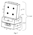
- the Fig. 1 to 8 show inter alia at least one Linearjustiermati 1 with a first component 2 and a second component 3, wherein the second component 3 has a linear guide 4, and the first component 2 is guided linearly within the second component 3, wherein a setting unit 5 comprising a spindle. 6 is provided, and the first component 2 relative to the second component 3 by means of the adjusting unit 5 is adjustable, wherein the spindle 6 is arranged between the first component 2 and the second component 3, and that the spindle 6 in operation of the first component 2 and the second component 3 is substantially hidden.
- a linear adjustment unit 1 can be formed, which is not susceptible to soiling and mechanical damage.
- the spindle 6 is protected by the first and the second component 2, 3 from contamination and mechanical damage.
- a compact design is further possible, which is suitable to absorb high forces.
- Inventive Linearjustiericaen 1 are preferably provided for receiving high forces, and are therefore preferably made of metallic materials, in particular comprising steel, titanium, tungsten, nickel, such as Neumonic, or der Eisene formed.
- a linear guide 4 for linear guidance of the first component 2 is formed in the second component 3.
- the linear guide 4 is designed such that the first component 2 is guided within the second component 3.
- the linear guide 4 in this case has a receptacle, which is formed in the second component 3, and which substantially completely accommodates the first component 2 in at least one rest position, wherein the first component 2 is formed at least partially corresponding to the receptacle in the second component 3.
- the linear guide 4 is preferably formed over an entire longitudinal extent of the second component 3.
- the receptacle has a shape which ensures a linear guidance of the first component 2 within the second component 3.
- the second component 3 therefore has a substantially concave cross-section at right angles to the adjustment direction, which is preferably designed such that it substantially completely accommodates the cross-section of the first component 2, wherein it is provided that the first component 2 projects beyond the second component 3, to ensure a relative displaceability of the two components 2, 3 to one another, even if a load is mounted on the first component 2, which projects beyond the first component 2. It is particularly preferred, as in the in the Fig. 1 to 8 illustrated preferred embodiment, provided that the receptacle is formed as a substantially U-shaped recess 7, or that the second component 3 has a substantially U-shaped recess 7 for receiving the first component 2.
- the first component 2 has a shape substantially opposite to that of the receptacle. It can thereby be achieved that the first component 2 essentially rests on the second component 3 over the entire common base area of the two components 2, 3, whereby high forces can be absorbed with a small size of the two components 2, 3, since the local Surface load can be kept low.
- the concave second component 3 has undercuts, and the first component 2 corresponding opposite projections 10.
- the Linearjustiertician 1 can be operated in different positions, without the first component 2 would be separated from the second component 3 under the action of gravity.
- Particular preference is hiebei provided that to the Legs 8 of the U-shaped recess 7 each have at least one groove 9 is arranged, wherein the U-shaped recess 7 together with the grooves 9 form the linear guide 4, and that the first component 2 is formed substantially equal to the U-shaped recess 7 is, and the grooves 9 substantially opposite projections 10 has.
- a linear adjustment unit 1 has at least one adjustment unit 5 for adjusting the first component 2 relative to the second component 3.
- This adjustment unit 5 has at least one spindle 6, which has at least a few threads in at least some areas, wherein thread-free areas can also be provided. It can also be provided that the spindle 6 has a multi-start thread.
- the spindle is designed as a threaded pin 14.
- a threaded pin 14, is a spindle 6, which has at least one thread over the full length, or which is formed only by the threaded portions having, and is free further actuating means, such as a screw head, a crank or the like.
- the spindle 6 thus formed has a receptacle, in particular a hexagon socket, square socket, Phillips, Torx, Potzidrive, Triwing or the like, for an adjustment tool.
- a receptacle in particular a hexagon socket, square socket, Phillips, Torx, Potzidrive, Triwing or the like, for an adjustment tool.
- the spindle 6 is mounted between the first and the second component 2, 3, wherein provision is made, in particular, for the spindle 6, or the adjustment unit 5 formed thereby, to be arranged within a spindle receptacle 11.
- the spindle 6 is rotatably supported within the spindle receptacle 11. Preferred and as in the Fig. 1 to 3 illustrated, provided that in the U-shaped recess 7, a spindle receptacle 11 is arranged, which is preferably formed trough-shaped or in the form of an overlapped closed slot-like depression which is slightly larger than the outer dimensions of the spindle 6.
- the spindle 6 is rotatably disposed without additional support within the spindle receptacle 11, but it can also be provided that the spindle 6 is rotatably mounted within the spindle receptacle 11, for example by means of ball bearings or plain bearings.
- the spindle receptacle 11 has an input region 12 in the form of an opening.
- the first component 2 is adjusted relative to the second component 3.
- the spindle 6 is mounted so as to be displaceable within the second component 3. It is therefore preferably provided that a, the U-shaped recess 7 facing first surface 13 of the first component 2 is at least partially formed for engagement of the spindle 6.
- the first surface 13 may be formed approximately in the form of an at least partially formed thread or threaded parts 34, or in the form of a rack. Particularly preferred and such as in Fig. 1 it is provided that the first surface 13 is at least partially formed opposite to a arranged in the spindle holder 11 threaded pin 14, therefore threaded parts 34 having a corresponding thread.
- the spindle 6 is substantially covered by the first component 2 and the second component 3 during operation.
- the linear adjustment unit 1 has means 15 for limiting the adjustability. It is preferably provided hiebei that the means 15 for limiting the adjustability comprise at least one elongated hole 16, with longitudinal extent in the adjustment direction 27 of the linear guide 4, and a pin 17 which engages in the slot 16. As a result, a simple mechanical limitation of the adjustability can be achieved, wherein different configurations can be provided.
- a slot 16 arranged only within the U-shaped recess 7 can be provided, into which a pin 17 engages, which is spring-actuated or can be pivoted into the oblong hole 16, for example by means of a key.
- the slot 16 is formed as a passage opening in the second component 3, for example as a passage opening in the region of a leg 8 of the U-shaped recess 7, and that the pin 17 is formed as a screw or bolt, whereby a simple Structure and a simple assembly of the linear adjustment unit 1 can be achieved.
- the elongated hole as shown having a support surface for a screw head, and the screw is tightened in the slot 16, wherein the screw head is pressed against the support surface.
- adjustment units 22, 23 from a predeterminable number of interconnected linear adjustment units 1 according to the invention, which allow an adjustment in a predeterminable number of dimensions, with one dimension each having an adjustment possibility along an adjustment direction 27, 28, 29 of one Linearjustiermaschine 1, 31, 32, 33 is designated.
- a two-dimensional adjustment unit 22 is formed by the direct connection of two linear adjustment units 1, 31, 32 according to the invention or that three-dimensional adjustment units 23 are formed by the direct connection of three linear adjustment units 1, 31, 32, 33 according to the invention.
- Immediately connected to each other is preferred as a connection of the individual Linearjustiertechniken 1 without the need for an adapter to understand, it being possible to arrange between the individual Linearjustiermaschineen 1 as sealant, threadlocker or damping mats.
- any type of connection of the individual linear adjustment units 1, 31, 32, 33 may be provided. It is particularly preferred that the individual Linearjustierillonen 1, 31, 32, 33 of such a multi-dimensional adjustment unit 22, 23 are connected by means of releasable connection means 26, such as by means of screws or mechanical quick-release fasteners. Hiebei it is provided that the first and / or the second component 2, 3 have connection means receptacles 18 for releasable connection means 26, which are preferably formed as through holes, wherein it can be provided that the through holes have an internal thread.
- the detachable connection means 26 are preferably designed as screws, wherein it is provided that the screws have a screw head with a receptacle, in particular a hexagon socket, square socket, Phillips, Torx, Potzidrive, Triwing or the like, for an adjusting tool. It is particularly preferred hiebei provided that the releasable connection means 26, formed as a screw pin 17 and / or the threaded pin 14 have identical receptacles for an adjustment. As a result, all adjustments to a linear adjustment unit 1 or an adjustment unit 22, 23 can be made with only a single adjustment tool.
- connection means receptacles 18 are preferably arranged such that they allow an adapterless connection of a first component 2 with a second component 3, wherein it is particularly preferred that in addition the adapterless connection in predetermined angles of the adjustment directions 27, 28, 29 of the individual Linearjustiericaen. 1 , 31, 32, 33 can be provided to each other.
- first component 2 and the second component 3 each have at least three connecting means receptacles 18, wherein a first connecting means receiving 18, 19 to their respective next adjacent second connecting means receiving 18, 20 and third connecting means receptacles 18, 21 has a predetermined constant distance.
- the first component 2 and the second component 3 each have the same number of kaus, and that arranged in the first component 2 kausungsstoffnessn 18, and disposed in the second component 3 gleichsungsstofffactn 18th are arranged in alignment with each other in at least one position or position of the first component 2 to the second component 3.
- the releasable connection means 26, which are arranged in the connecting means receptacles 18 in one of the two components 2, 3, are actuated by the connecting means receptacles 18 in the respective other component 3, 2 by an adjusting tool, such as a screwdriver or a so-called.
- At least one End side 30 of the first component 2 and / or the second component 3 are arranged at least two connecting means receptacles 18 which have the constant distance to each other.
- a two-dimensional adjusting unit 22 is particularly preferred to design a two-dimensional adjusting unit 22 as a so-called XY adjusting unit 24, wherein a first linear adjusting unit 1, 31 according to the invention is directly connected to a second linear adjusting unit 1, 32 according to the invention by means of detachable connecting means 26, wherein the adjusting direction 27 of the first linear adjusting unit 1, 31 is arranged substantially normal to the adjustment direction 28 of the second linear adjustment unit 1, 32.
- a very compact heavy-duty X-Y adjustment unit can be formed, which is insensitive to contamination and mechanical damage, and can be formed without additional adapters.
- a three-dimensional adjusting unit 23 as a so-called XYZ adjusting unit 25, wherein a third linear adjusting unit 1, 33 according to the invention is directly connected to an XY adjusting unit 24 described above by means of detachable connecting means 26, the adjusting direction 29 of the third linear adjusting unit 1 33 is arranged substantially normal to the adjustment direction 27 of the first linear adjustment unit 1, 31 and the adjustment direction 28 of the second linear adjustment unit 1, 32, whereby a very compact heavy duty XYZ adjustment unit can be formed, which is insensitive to contamination and mechanical damage, and can be formed without additional adapters.
- X, Y and Z denote in a conventional manner the axes of a Cartesian coordinate system. The Fig.
- each used Linearjustierussien (1, 31, 32, 33) each have identical dimensions and at each identical positions arranged connecting means receptacles (18), as for example from the Fig. 5 to 8 evident.
Landscapes
- Engineering & Computer Science (AREA)
- General Engineering & Computer Science (AREA)
- Mechanical Engineering (AREA)
- Endoscopes (AREA)
- Prostheses (AREA)
- Measurement Of Force In General (AREA)
- Particle Formation And Scattering Control In Inkjet Printers (AREA)
- Measuring Pulse, Heart Rate, Blood Pressure Or Blood Flow (AREA)
- Pinball Game Machines (AREA)
Applications Claiming Priority (1)
| Application Number | Priority Date | Filing Date | Title |
|---|---|---|---|
| AT3862008A AT506516B1 (de) | 2008-03-11 | 2008-03-11 | Linearjustiereinheit |
Publications (2)
| Publication Number | Publication Date |
|---|---|
| EP2101068A2 true EP2101068A2 (fr) | 2009-09-16 |
| EP2101068A3 EP2101068A3 (fr) | 2010-11-17 |
Family
ID=40823227
Family Applications (1)
| Application Number | Title | Priority Date | Filing Date |
|---|---|---|---|
| EP09450054A Withdrawn EP2101068A3 (fr) | 2008-03-11 | 2009-03-11 | Unité de réglage |
Country Status (2)
| Country | Link |
|---|---|
| EP (1) | EP2101068A3 (fr) |
| AT (1) | AT506516B1 (fr) |
Cited By (4)
| Publication number | Priority date | Publication date | Assignee | Title |
|---|---|---|---|---|
| CN104265783A (zh) * | 2014-07-30 | 2015-01-07 | 成都大宏立机器股份有限公司 | 惯性圆锥破碎机连接装置、破碎机及装配方法 |
| WO2015038081A3 (fr) * | 2013-09-16 | 2015-06-11 | Yüksel Eyüp Osman | Ensemble de réglage axial sans tôle forte de revêtement |
| CN108825602A (zh) * | 2018-09-05 | 2018-11-16 | 深圳华加日幕墙科技有限公司 | 围栏装饰件连接结构 |
| CN118919385A (zh) * | 2024-07-16 | 2024-11-08 | 颀中科技(苏州)有限公司 | 载具 |
Family Cites Families (7)
| Publication number | Priority date | Publication date | Assignee | Title |
|---|---|---|---|---|
| DE973832C (de) * | 1949-10-23 | 1960-06-15 | Siepmann Werke Ag | Aus Schmiedestuecken bestehender Parallelschraubstock |
| SU632493A1 (ru) * | 1977-06-06 | 1978-11-15 | Пермский Моторостроительный Завод Имени Я.М.Свердлова | Суппорт металлорежущего станка |
| US4417771A (en) * | 1982-06-22 | 1983-11-29 | Hiroshi Teramachi | Linear ball bearing unit |
| US5547330A (en) * | 1994-09-22 | 1996-08-20 | Walimaa; Edsel J. | Ergonomic three axis positioner |
| JP3178978B2 (ja) * | 1994-10-24 | 2001-06-25 | 株式会社イマオコーポレーション | 取付補助部材 |
| JP2001500435A (ja) * | 1996-09-13 | 2001-01-16 | ビットムーア ヴァイス アン オレゴン ゼネラル パートナーシップ | 二重調節可能の万力 |
| US6174102B1 (en) * | 1998-01-26 | 2001-01-16 | New Focus, Inc. | Modular motion stages utilizing interconnecting elements |
-
2008
- 2008-03-11 AT AT3862008A patent/AT506516B1/de not_active IP Right Cessation
-
2009
- 2009-03-11 EP EP09450054A patent/EP2101068A3/fr not_active Withdrawn
Cited By (6)
| Publication number | Priority date | Publication date | Assignee | Title |
|---|---|---|---|---|
| WO2015038081A3 (fr) * | 2013-09-16 | 2015-06-11 | Yüksel Eyüp Osman | Ensemble de réglage axial sans tôle forte de revêtement |
| CN104265783A (zh) * | 2014-07-30 | 2015-01-07 | 成都大宏立机器股份有限公司 | 惯性圆锥破碎机连接装置、破碎机及装配方法 |
| CN108825602A (zh) * | 2018-09-05 | 2018-11-16 | 深圳华加日幕墙科技有限公司 | 围栏装饰件连接结构 |
| CN108825602B (zh) * | 2018-09-05 | 2023-12-29 | 深圳广晟幕墙科技有限公司 | 围栏装饰件连接结构 |
| CN118919385A (zh) * | 2024-07-16 | 2024-11-08 | 颀中科技(苏州)有限公司 | 载具 |
| CN118919385B (zh) * | 2024-07-16 | 2025-10-03 | 颀中科技(苏州)有限公司 | 载具 |
Also Published As
| Publication number | Publication date |
|---|---|
| AT506516B1 (de) | 2012-09-15 |
| EP2101068A3 (fr) | 2010-11-17 |
| AT506516A1 (de) | 2009-09-15 |
Similar Documents
| Publication | Publication Date | Title |
|---|---|---|
| EP0490086B1 (fr) | Raccord à vis pour assembler au moins deux pièces de manière détachable, notamment des barres profilées pourvues de rainures longitudinales | |
| DE69313708T2 (de) | Führungseinheit für geradlinige Wälzbewegung | |
| DE60002560T2 (de) | Schneidwerkzeuganordnung und schneideinsatz dafür | |
| DE202017006852U1 (de) | Verbindungsstück für die feste Verbindung einer ersten und einer zweiten Platte von Möbelstücken und anderen Einrichtungsgegenständen | |
| AT506516B1 (de) | Linearjustiereinheit | |
| DE102015115294B4 (de) | Nivellierschuh und System mit einem solchen Nivellierschuh | |
| DE202010009471U1 (de) | Werkzeug für die spanende Bearbeitung, insbesondere Drehwerkzeug | |
| DE69212158T2 (de) | Vorrichtung um brettartige elemente zu einer einheit zu verbinden | |
| DE202015105073U1 (de) | Drehhaltervorrichtung für Drehmaschinen | |
| DE19701428C2 (de) | In einer Ausnehmung einer Türbekleidung angeordnetes Winkelschließblech | |
| EP3828426B1 (fr) | Élément de fixation pour tubes à plusieurs bordures | |
| AT520767A1 (de) | Anordnung aus einem Auflagesteg für einen Schubladenboden und einer Haltevorrichtung | |
| DE69002342T2 (de) | Befestigungsvorrichtung durch Zusammenschrauben auf einem Profil, insbesondere auf einem Elektrizitätsschrank. | |
| DE102021116812A1 (de) | Erweiterungsbausatz | |
| EP2394790A2 (fr) | Mors de rechange pour un étau | |
| EP1630312B1 (fr) | Connecteur de murs | |
| DE4003602C2 (de) | Vorrichtung mit zwei Klemmflächen zum lösbaren Verbinden von Bauelementen | |
| WO2026060460A1 (fr) | Paroi, de préférence paroi arrière, pour bloc-tiroirs | |
| WO2026060462A1 (fr) | Dispositif de réglage de l'inclinaison d'un panneau avant | |
| DE10300650B3 (de) | Verbindungselement für einen Handlauf | |
| DE202020000067U1 (de) | Möbel | |
| EP2997315A2 (fr) | Système permettant d'assembler deux éléments | |
| DE202025107749U1 (de) | Profilstab und Anordnung mit mindestens einem Profilstab | |
| DE202023106463U1 (de) | Verbindungssystem zum Verbinden einer Mehrzahl von Profilleisten und Zentralelement zur Verwendung mit einem Verbindungssystem zum Verbinden einer Mehrzahl von Profilleisten | |
| DE202016100903U1 (de) | Regalelementanordnung sowie Verbindungselement für eine Regalelementanordnung |
Legal Events
| Date | Code | Title | Description |
|---|---|---|---|
| PUAI | Public reference made under article 153(3) epc to a published international application that has entered the european phase |
Free format text: ORIGINAL CODE: 0009012 |
|
| AK | Designated contracting states |
Kind code of ref document: A2 Designated state(s): AT BE BG CH CY CZ DE DK EE ES FI FR GB GR HR HU IE IS IT LI LT LU LV MC MK MT NL NO PL PT RO SE SI SK TR |
|
| AX | Request for extension of the european patent |
Extension state: AL BA RS |
|
| PUAL | Search report despatched |
Free format text: ORIGINAL CODE: 0009013 |
|
| AK | Designated contracting states |
Kind code of ref document: A3 Designated state(s): AT BE BG CH CY CZ DE DK EE ES FI FR GB GR HR HU IE IS IT LI LT LU LV MC MK MT NL NO PL PT RO SE SI SK TR |
|
| AX | Request for extension of the european patent |
Extension state: AL BA RS |
|
| RIC1 | Information provided on ipc code assigned before grant |
Ipc: B23Q 1/62 20060101ALI20101014BHEP Ipc: F16M 11/04 20060101ALI20101014BHEP Ipc: F16M 11/12 20060101ALI20101014BHEP Ipc: F16B 5/02 20060101AFI20090710BHEP |
|
| REG | Reference to a national code |
Ref country code: DE Ref legal event code: R108 |
|
| AKY | No designation fees paid | ||
| REG | Reference to a national code |
Ref country code: DE Ref legal event code: R108 Effective date: 20110714 |
|
| STAA | Information on the status of an ep patent application or granted ep patent |
Free format text: STATUS: THE APPLICATION IS DEEMED TO BE WITHDRAWN |
|
| 18D | Application deemed to be withdrawn |
Effective date: 20110518 |