EP2101082A2 - Hydraulischer Selbstspanner - Google Patents
Hydraulischer Selbstspanner Download PDFInfo
- Publication number
- EP2101082A2 EP2101082A2 EP09002781A EP09002781A EP2101082A2 EP 2101082 A2 EP2101082 A2 EP 2101082A2 EP 09002781 A EP09002781 A EP 09002781A EP 09002781 A EP09002781 A EP 09002781A EP 2101082 A2 EP2101082 A2 EP 2101082A2
- Authority
- EP
- European Patent Office
- Prior art keywords
- cylinder
- pressure
- throttle
- rod
- path
- Prior art date
- Legal status (The legal status is an assumption and is not a legal conclusion. Google has not performed a legal analysis and makes no representation as to the accuracy of the status listed.)
- Withdrawn
Links
- 239000010720 hydraulic oil Substances 0.000 claims abstract description 26
- 239000011148 porous material Substances 0.000 claims description 3
- 238000013016 damping Methods 0.000 description 8
- 239000003921 oil Substances 0.000 description 7
- 230000008878 coupling Effects 0.000 description 4
- 238000010168 coupling process Methods 0.000 description 4
- 238000005859 coupling reaction Methods 0.000 description 4
- 239000000872 buffer Substances 0.000 description 3
- 230000007423 decrease Effects 0.000 description 2
- 238000005553 drilling Methods 0.000 description 2
- 230000005540 biological transmission Effects 0.000 description 1
- 230000000694 effects Effects 0.000 description 1
- 238000004519 manufacturing process Methods 0.000 description 1
- XLYOFNOQVPJJNP-UHFFFAOYSA-N water Substances O XLYOFNOQVPJJNP-UHFFFAOYSA-N 0.000 description 1
Images


Classifications
-
- F—MECHANICAL ENGINEERING; LIGHTING; HEATING; WEAPONS; BLASTING
- F16—ENGINEERING ELEMENTS AND UNITS; GENERAL MEASURES FOR PRODUCING AND MAINTAINING EFFECTIVE FUNCTIONING OF MACHINES OR INSTALLATIONS; THERMAL INSULATION IN GENERAL
- F16H—GEARING
- F16H7/00—Gearings for conveying rotary motion by endless flexible members
- F16H7/08—Means for varying tension of belts, ropes or chains
- F16H7/10—Means for varying tension of belts, ropes or chains by adjusting the axis of a pulley
- F16H7/12—Means for varying tension of belts, ropes or chains by adjusting the axis of a pulley of an idle pulley
- F16H7/1209—Means for varying tension of belts, ropes or chains by adjusting the axis of a pulley of an idle pulley with vibration damping means
- F16H7/1236—Means for varying tension of belts, ropes or chains by adjusting the axis of a pulley of an idle pulley with vibration damping means of the fluid and restriction type, e.g. dashpot
-
- F—MECHANICAL ENGINEERING; LIGHTING; HEATING; WEAPONS; BLASTING
- F16—ENGINEERING ELEMENTS AND UNITS; GENERAL MEASURES FOR PRODUCING AND MAINTAINING EFFECTIVE FUNCTIONING OF MACHINES OR INSTALLATIONS; THERMAL INSULATION IN GENERAL
- F16H—GEARING
- F16H7/00—Gearings for conveying rotary motion by endless flexible members
- F16H7/08—Means for varying tension of belts, ropes or chains
- F16H2007/0802—Actuators for final output members
- F16H2007/0806—Compression coil springs
-
- F—MECHANICAL ENGINEERING; LIGHTING; HEATING; WEAPONS; BLASTING
- F16—ENGINEERING ELEMENTS AND UNITS; GENERAL MEASURES FOR PRODUCING AND MAINTAINING EFFECTIVE FUNCTIONING OF MACHINES OR INSTALLATIONS; THERMAL INSULATION IN GENERAL
- F16H—GEARING
- F16H7/00—Gearings for conveying rotary motion by endless flexible members
- F16H7/08—Means for varying tension of belts, ropes or chains
- F16H7/0848—Means for varying tension of belts, ropes or chains with means for impeding reverse motion
- F16H2007/0859—Check valves
Definitions
- This invention relates to a hydraulic auto-tensioner for adjusting the tension of a drive belt for driving automobile engine accessories such as an alternator, a water pump and a compressor of an air conditioner.
- a pivotable pulley arm 43 that supports a tension pulley 42 is provided on the slack side of a belt 41 and adjusting force of a hydraulic auto-tensioner A is applied to the pulley arm 43 to bias the pulley arm 43 in the direction that the tension pulley 42 pushes the belt 41. This keeps the tension of the belt 41 constant.
- This hydraulic auto-tensioner comprises a cylinder having a closed bottom and filled with hydraulic oil, a sleeve that extends from the inner bottom surface of the cylinder, a rod with its lower side slidably inserted in the sleeve to define a pressure chamber inside the sleeve, a spring seat provided on the upper side of the rod, and a return spring mounted between the spring seat and the bottom surface of the cylinder to bias the rod and the cylinder so that they extends relative to each other.
- This tensioner further includes an elastic bellows with its ends fit to the spring seat and to the upper end of the outer circumference of the cylinder, respectively, defining a closed reservoir chamber between the cylinder and the sleeve.
- the bottom of the reservoir chamber communicates with the pressure chamber through a path in which a check valve is provided.
- the object of this invention is to provide a hydraulic auto-tensioner that can prevent excessive tension of the belt.
- this invention provides a hydraulic auto-tensioner comprising a cylinder having a closed bottom end and filled with hydraulic oil, a sleeve mounted in the cylinder and uprising from the inner bottom surface of the cylinder, a rod with its lower end slidably inserted in the sleeve and defining a pressure chamber in the sleeve, a spring seat provided on the top of the rod, a return spring mounted between the spring seat and the inner bottom surface of the cylinder, and biasing the cylinder and the rod in such a direction that the rod protrudes from the cylinder, wherein a reservoir chamber is defined between the cylinder and the sleeve, the upper opening of the reservoir chamber being closed, and a check valve provided in a path communicating the reservoir chamber with the pressure chamber for closing the path when the pressure in the pressure chamber exceeds the pressure in the reservoir chamber, characterized in that the rod is formed with a communicating path communicating the pressure chamber with the reservoir chamber, a relief valve is mounted in the communicating
- a communicating path is formed in the rod so that the pressure chamber and the reservoir chamber communicate with each other, and the relief valve is mounted in the communicating path.
- the relief valve opens and hydraulic oil in the pressure chamber flows to the reservoir chamber through the communicating path.
- the throttle may be a small diameter hole, but forming a hole on the rod itself by drilling is difficult and takes a higher cost.
- the cost for forming the throttle can be reduced with configurations such as the following examples.
- pressure in the pressure chamber increases when pushing force is applied from the belt to the rod.
- this pressure exceeds the set pressure of the relief valve, the relief valve opens and hydraulic oil in the pressure chamber flows into the reservoir chamber through the communicating path. This keeps the upper limit of damping force generated in the pressure chamber to the set pressure of the relief valve, and therefore prevents excessive tension on the belt that decreases durability of the belt.
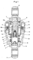
- the tensioner includes a cylinder 1 provided with a closed bottom on which a coupling piece 2 is provided which can be rotatably coupled to an engine block.
- a sleeve fitting hole 3 On the inner bottom surface of the cylinder 1, a sleeve fitting hole 3 is provided. The lower portion of a sleeve 4 is pressed into the sleeve fitting hole 3. The lower portion of a rod 5 is slidably inserted in the sleeve 4. The rod 5 defines a pressure chamber 6 in the sleeve 4.
- a spring seat 7 is mounted on the top end of the rod 5, which is located outside the cylinder 1.
- a return spring 8 is mounted between the spring seat 7 and the bottom surface of the cylinder 1, biasing the cylinder 1 and the rod 5 in such a direction that the rod 5 protrudes from the cylinder 1.
- the spring seat 7 is provided with a coupling piece 9 at its top end that is to be coupled to a pulley arm 43 shown in Fig. 4 . Also the spring seat 7 is provided with an inner cylindrical portion 10 covering the upper portion of the return spring 8 and an outer cylindrical portion 11 covering the upper portion of the outer circumference of the cylinder 1 and coaxial with the inner cylindrical portion 10.
- An elastic seal 12 such as an oil seal is attached in the upper opening of the cylinder 1.
- the inner circumference of the elastic seal 12 elastically contacts the outer circumference of the inner cylindrical portion 10, and closes the upper opening of the cylinder, preventing hydraulic oil in the cylinder 1 from leaking.
- the elastic seal 12 defines a closed reservoir chamber 13 between the cylinder 1 and the sleeve 4.
- the reservoir chamber 13 and the pressure chamber 6 communicate with each other through a path 14 formed between the fitting surfaces of the sleeve fitting hole 3 and the sleeve 4.
- a check valve 15 is provided at the end of the path 14 near the pressure chamber 6. The check valve 15 closes the path 14 when the pressure in the pressure chamber 6 exceeds the pressure in the reservoir chamber 13.
- the rod 5 is provided with a communicating path 16, communicating the pressure chamber 6 and the reservoir chamber 13 with each other.
- the communicating path 16 comprises an axial path 16a that extends axially from the lower end of the rod 5 and a diametrical path 16b that communicates with the upper end of the axial path 16a and extends in the diameter direction of the rod 5.
- a valve fitting hole 17 is provided in which a relief valve 18 is mounted.
- the relief valve 18 is an assembly comprising a cylindrical member 19 with a small hole formed at its closed end, a valve seat 21 closing the other open end of the cylindrical member 19, a spherical valve body 23 that opens and closes a valve hole 22 formed in the valve seat 21, and a valve spring 24 that biases the valve body 23 toward the valve hole 22.
- the cylindrical member 19 has an outer diameter smaller than the inner diameter of the valve fitting hole 17, leaving a slight clearance therebetween when the cylinder member 19 is inserted in the valve fitting hole 17.
- a retainer 25 is provided in the open end of the valve fitting hole 17, preventing the relief valve 18 from coming off.
- the retainer 25 is cup-shaped, comprising a disk portion 26 and a cylindrical portion 27 formed on the outer edge of the disk portion 26.
- the retainer 25 is mounted in position with its cylindrical portion 27 pressed in the valve fitting hole 17.
- the disk portion 26 has a center hole 28 with a diameter larger than the inner diameter of the valve hole 22 formed in the valve seat 21.
- a female thread 31 is formed on the inner circumference of the axial path 16a of the communicating path 16 at its lower end.
- a set screw 32 has its male thread 33 in threaded engagement with the female thread 31.
- a clearance between the male thread 33 and the female thread 31 serves as a throttle 34.
- the coupling piece 2 is coupled to an engine block and the coupling piece 9 on the spring seat 7 is coupled to the pulley arm 43 so that an adjusting force is imparted to the pulley arm 43.
- the tension of the belt 41 fluctuates by factors such as fluctuation in the load on the engine accessory.
- the return spring 8 pushes the cylinder 1 and the rod 5 so that they displace relative to each other in the extending direction, and the looseness of the belt 41 is removed.
- the upper limit of the pressure in the pressure chamber 6 can be kept to the set pressure of the relief valve 18. This prevents excessive tension on the belt 41 and thus improves the durability of the belt 41.
- the throttle 34 prevents a pressure drop at the hydraulic oil outlet of the relief valve 18, the pressure difference between the inlet and outlet of the relief valve 18 can be kept small. This in turn prevents vibration of the valve body 23, which leads to collision of the valve body 23 to the seat face 30 of the valve seat 21 and generates noise.
- a female thread 31 is formed on the inner circumference of the axial path 16a at its lower end, and the set screw 32 has its male thread 33 in threaded engagement with the female thread 31.
- the throttle 34 is provided in the form of a clearance between the male thread 33 and the female thread 31, but the throttle is not limited to this form.
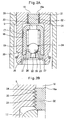
- a set screw 32 is pressed in the lower end of the axial path 16a of the communicating path 16, and the groove of the male thread 33 formed on the outer circumference of the set screw 32 is defined as a throttle 34.
- a female thread 31 is formed on the inner circumference of the lower end of the axial path 16a of the communicating path 16, and a cylindrical body 36 is pressed in the female thread 31.
- the groove of the female thread 31 is defined as a throttle 34.
- a cylindrical porous body 37 is pressed in the lower end of the axial path 16a of the communicating path 16, and the open pores of the porous body 37 are defined as a throttle 34.
- a cylindrical body 38 is pressed in the lower end of the axial path 16a of the communicating path 16, and a center hole with a small diameter formed in the center of the cylindrical body 38 is defined as a throttle 34.
- the throttle 34 can be formed more easily than drilling a small diameter throttle on the rod 5, and this reduces the manufacturing cost.
Landscapes
- Engineering & Computer Science (AREA)
- General Engineering & Computer Science (AREA)
- Mechanical Engineering (AREA)
- Devices For Conveying Motion By Means Of Endless Flexible Members (AREA)
Applications Claiming Priority (1)
| Application Number | Priority Date | Filing Date | Title |
|---|---|---|---|
| JP2008064380A JP2009222081A (ja) | 2008-03-13 | 2008-03-13 | 油圧式オートテンショナ |
Publications (2)
| Publication Number | Publication Date |
|---|---|
| EP2101082A2 true EP2101082A2 (de) | 2009-09-16 |
| EP2101082A3 EP2101082A3 (de) | 2009-10-14 |
Family
ID=40688381
Family Applications (1)
| Application Number | Title | Priority Date | Filing Date |
|---|---|---|---|
| EP09002781A Withdrawn EP2101082A3 (de) | 2008-03-13 | 2009-02-26 | Hydraulischer Selbstspanner |
Country Status (2)
| Country | Link |
|---|---|
| EP (1) | EP2101082A3 (de) |
| JP (1) | JP2009222081A (de) |
Cited By (11)
| Publication number | Priority date | Publication date | Assignee | Title |
|---|---|---|---|---|
| DE102010045877A1 (de) | 2010-09-17 | 2012-03-22 | Schaeffler Technologies Gmbh & Co. Kg | Hydraulisch gedämpfte Spannvorrichtung mit variablem Druckraum |
| DE102010049905A1 (de) | 2010-10-28 | 2012-05-03 | Schaeffler Technologies Gmbh & Co. Kg | Definierter Systemdruck in einem hydraulisch gedämpften Spannsystem |
| DE102011004486A1 (de) | 2011-02-22 | 2012-08-23 | Schaeffler Technologies AG & Co. KG | Spannsystem für einen Zugmitteltrieb mit einer integrierten Überdruckeinheit |
| CN102840290A (zh) * | 2012-08-15 | 2012-12-26 | 平湖康弗莱尔汽车发动机系统有限公司 | 机械式张紧器 |
| DE102011088214A1 (de) | 2011-12-12 | 2013-06-13 | Schaeffler Technologies AG & Co. KG | Hydraulischer Automatikspanner |
| DE102012212057A1 (de) | 2012-07-11 | 2014-01-16 | Schaeffler Technologies AG & Co. KG | Druckfedersystem für einen hydraulisch betriebenen Zugmittelspanner |
| DE102012223329A1 (de) | 2012-08-13 | 2014-02-13 | Schaeffler Technologies AG & Co. KG | Hydraulischer Automatikspanner |
| WO2014056499A1 (de) | 2012-10-11 | 2014-04-17 | Schaeffler Technologies AG & Co. KG | Hydraulische spannvorrichtung |
| DE102013006618A1 (de) * | 2013-04-17 | 2014-10-23 | Iwis Motorsysteme Gmbh & Co. Kg | Spannvorrichtung mit porösem Dämpfungseinsatz |
| CN105473897A (zh) * | 2013-09-26 | 2016-04-06 | Ntn株式会社 | 油压式自动张紧器 |
| DE102016204178A1 (de) | 2016-03-15 | 2017-09-21 | Schaeffler Technologies AG & Co. KG | Zugmittelspanner mit Anschlag |
Families Citing this family (4)
| Publication number | Priority date | Publication date | Assignee | Title |
|---|---|---|---|---|
| WO2015115555A1 (ja) * | 2014-01-31 | 2015-08-06 | Ntn株式会社 | 油圧式オートテンショナ |
| JP6263409B2 (ja) * | 2014-02-20 | 2018-01-17 | Ntn株式会社 | 油圧式オートテンショナ |
| JP6234252B2 (ja) * | 2014-01-31 | 2017-11-22 | Ntn株式会社 | 油圧式オートテンショナ |
| JP6505794B2 (ja) * | 2017-08-29 | 2019-04-24 | Ntn株式会社 | 油圧式オートテンショナ |
Citations (1)
| Publication number | Priority date | Publication date | Assignee | Title |
|---|---|---|---|---|
| JP2000504395A (ja) | 1995-05-18 | 2000-04-11 | イナ ベルツラーゲル シエツフレル オツフエネ ハンデルスゲゼルシヤフト | 牽引機構のための液圧式緊締装置 |
Family Cites Families (8)
| Publication number | Priority date | Publication date | Assignee | Title |
|---|---|---|---|---|
| DE3217632A1 (de) * | 1982-05-11 | 1983-11-17 | Porsche Ag | Hydraulischer kettenspanner |
| DE4039816C1 (en) * | 1990-12-13 | 1992-04-09 | Mercedes-Benz Aktiengesellschaft, 7000 Stuttgart, De | Belt drive tensioning system - uses cylinder with springs and damping fluid |
| US5718650A (en) * | 1996-10-03 | 1998-02-17 | Borg-Warner Automotive, Inc. | Hydraulic tensioner with porous vent |
| JP3707447B2 (ja) * | 2002-05-29 | 2005-10-19 | 株式会社ショーワ | 油圧式オートテンショナー |
| JP4214090B2 (ja) * | 2004-08-02 | 2009-01-28 | 本田技研工業株式会社 | オートテンショナ |
| JP2007107605A (ja) * | 2005-10-13 | 2007-04-26 | Ntn Corp | オートテンショナ |
| JP2008032122A (ja) * | 2006-07-28 | 2008-02-14 | Ntn Corp | 油圧式オートテンショナ |
| JP2008032124A (ja) * | 2006-07-28 | 2008-02-14 | Ntn Corp | 油圧式オートテンショナ |
-
2008
- 2008-03-13 JP JP2008064380A patent/JP2009222081A/ja active Pending
-
2009
- 2009-02-26 EP EP09002781A patent/EP2101082A3/de not_active Withdrawn
Patent Citations (1)
| Publication number | Priority date | Publication date | Assignee | Title |
|---|---|---|---|---|
| JP2000504395A (ja) | 1995-05-18 | 2000-04-11 | イナ ベルツラーゲル シエツフレル オツフエネ ハンデルスゲゼルシヤフト | 牽引機構のための液圧式緊締装置 |
Cited By (17)
| Publication number | Priority date | Publication date | Assignee | Title |
|---|---|---|---|---|
| DE102010045877A1 (de) | 2010-09-17 | 2012-03-22 | Schaeffler Technologies Gmbh & Co. Kg | Hydraulisch gedämpfte Spannvorrichtung mit variablem Druckraum |
| DE102010049905A1 (de) | 2010-10-28 | 2012-05-03 | Schaeffler Technologies Gmbh & Co. Kg | Definierter Systemdruck in einem hydraulisch gedämpften Spannsystem |
| DE102011004486A1 (de) | 2011-02-22 | 2012-08-23 | Schaeffler Technologies AG & Co. KG | Spannsystem für einen Zugmitteltrieb mit einer integrierten Überdruckeinheit |
| DE102011004486B4 (de) * | 2011-02-22 | 2020-03-12 | Schaeffler Technologies AG & Co. KG | Spannsystem für einen Zugmitteltrieb mit einer integrierten Überdruckeinheit |
| DE102011088214A1 (de) | 2011-12-12 | 2013-06-13 | Schaeffler Technologies AG & Co. KG | Hydraulischer Automatikspanner |
| DE102012212057A1 (de) | 2012-07-11 | 2014-01-16 | Schaeffler Technologies AG & Co. KG | Druckfedersystem für einen hydraulisch betriebenen Zugmittelspanner |
| DE102012223329A1 (de) | 2012-08-13 | 2014-02-13 | Schaeffler Technologies AG & Co. KG | Hydraulischer Automatikspanner |
| WO2014026798A1 (de) | 2012-08-13 | 2014-02-20 | Schaeffler Technologies AG & Co. KG | Hydraulischer automatikspanner |
| CN102840290B (zh) * | 2012-08-15 | 2015-04-15 | 平湖康弗莱尔汽车发动机系统有限公司 | 机械式张紧器 |
| CN102840290A (zh) * | 2012-08-15 | 2012-12-26 | 平湖康弗莱尔汽车发动机系统有限公司 | 机械式张紧器 |
| WO2014056499A1 (de) | 2012-10-11 | 2014-04-17 | Schaeffler Technologies AG & Co. KG | Hydraulische spannvorrichtung |
| DE102012218524A1 (de) | 2012-10-11 | 2014-04-17 | Schaeffler Technologies Gmbh & Co. Kg | Hydraulische Spannvorrichtung |
| DE102013006618A1 (de) * | 2013-04-17 | 2014-10-23 | Iwis Motorsysteme Gmbh & Co. Kg | Spannvorrichtung mit porösem Dämpfungseinsatz |
| CN105473897A (zh) * | 2013-09-26 | 2016-04-06 | Ntn株式会社 | 油压式自动张紧器 |
| US9677649B2 (en) | 2013-09-26 | 2017-06-13 | Ntn Corporation | Hydraulic auto-tensioner |
| CN105473897B (zh) * | 2013-09-26 | 2018-04-06 | Ntn株式会社 | 油压式自动张紧器 |
| DE102016204178A1 (de) | 2016-03-15 | 2017-09-21 | Schaeffler Technologies AG & Co. KG | Zugmittelspanner mit Anschlag |
Also Published As
| Publication number | Publication date |
|---|---|
| EP2101082A3 (de) | 2009-10-14 |
| JP2009222081A (ja) | 2009-10-01 |
Similar Documents
| Publication | Publication Date | Title |
|---|---|---|
| EP2101082A2 (de) | Hydraulischer Selbstspanner | |
| JP5567300B2 (ja) | 油圧式オートテンショナ | |
| US20140057748A1 (en) | Hydraulic auto-tensioner | |
| JP5086171B2 (ja) | 油圧式オートテンショナ | |
| WO2013103098A1 (ja) | 油圧式オートテンショナ | |
| US20130260931A1 (en) | Hydraulic auto-tensioner | |
| JP5112937B2 (ja) | 油圧式オートテンショナ | |
| JP2009270642A (ja) | 油圧式オートテンショナ | |
| WO2009101915A1 (ja) | 油圧式オートテンショナ | |
| US20100048334A1 (en) | Hydraulic tensioning unit for flexible drives | |
| JP2010276152A (ja) | オートテンショナ | |
| JP2009257412A (ja) | 油圧式オートテンショナ | |
| JP5992688B2 (ja) | 油圧式オートテンショナ | |
| JP2010249273A (ja) | オートテンショナ | |
| JP5820626B2 (ja) | 油圧式オートテンショナ | |
| JP4898403B2 (ja) | チェーンテンショナ | |
| WO2017030051A1 (ja) | 油圧式オートテンショナ | |
| JP2008202776A (ja) | 油圧式オートテンショナ | |
| JP2007218401A (ja) | 油圧式オートテンショナ | |
| JP2013142405A (ja) | 油圧式オートテンショナ | |
| JP2008248925A (ja) | 油圧式オートテンショナ | |
| JP4698457B2 (ja) | 油圧式オートテンショナ | |
| JP2008032126A (ja) | 油圧式オートテンショナ | |
| JP4485935B2 (ja) | オートテンショナの流体ダンピング機構 | |
| JP2009162320A (ja) | オートテンショナ |
Legal Events
| Date | Code | Title | Description |
|---|---|---|---|
| PUAI | Public reference made under article 153(3) epc to a published international application that has entered the european phase |
Free format text: ORIGINAL CODE: 0009012 |
|
| PUAL | Search report despatched |
Free format text: ORIGINAL CODE: 0009013 |
|
| AK | Designated contracting states |
Kind code of ref document: A2 Designated state(s): AT BE BG CH CY CZ DE DK EE ES FI FR GB GR HR HU IE IS IT LI LT LU LV MC MK MT NL NO PL PT RO SE SI SK TR |
|
| AX | Request for extension of the european patent |
Extension state: AL BA RS |
|
| AK | Designated contracting states |
Kind code of ref document: A3 Designated state(s): AT BE BG CH CY CZ DE DK EE ES FI FR GB GR HR HU IE IS IT LI LT LU LV MC MK MT NL NO PL PT RO SE SI SK TR |
|
| AX | Request for extension of the european patent |
Extension state: AL BA RS |
|
| RIC1 | Information provided on ipc code assigned before grant |
Ipc: F16H 7/12 20060101ALI20090904BHEP Ipc: F16H 7/08 20060101AFI20090610BHEP |
|
| AKX | Designation fees paid | ||
| STAA | Information on the status of an ep patent application or granted ep patent |
Free format text: STATUS: THE APPLICATION IS DEEMED TO BE WITHDRAWN |
|
| 18D | Application deemed to be withdrawn |
Effective date: 20100415 |
|
| REG | Reference to a national code |
Ref country code: DE Ref legal event code: 8566 |