EP2101095A2 - Tuyau ondulé en matière plastique destiné à gainer au moins un câble de capteur de gaz d'échappement - Google Patents
Tuyau ondulé en matière plastique destiné à gainer au moins un câble de capteur de gaz d'échappement Download PDFInfo
- Publication number
- EP2101095A2 EP2101095A2 EP09001804A EP09001804A EP2101095A2 EP 2101095 A2 EP2101095 A2 EP 2101095A2 EP 09001804 A EP09001804 A EP 09001804A EP 09001804 A EP09001804 A EP 09001804A EP 2101095 A2 EP2101095 A2 EP 2101095A2
- Authority
- EP
- European Patent Office
- Prior art keywords
- corrugated
- exhaust gas
- sectional area
- gas sensor
- corrugated hose
- Prior art date
- Legal status (The legal status is an assumption and is not a legal conclusion. Google has not performed a legal analysis and makes no representation as to the accuracy of the status listed.)
- Withdrawn
Links
Images
Classifications
-
- F—MECHANICAL ENGINEERING; LIGHTING; HEATING; WEAPONS; BLASTING
- F16—ENGINEERING ELEMENTS AND UNITS; GENERAL MEASURES FOR PRODUCING AND MAINTAINING EFFECTIVE FUNCTIONING OF MACHINES OR INSTALLATIONS; THERMAL INSULATION IN GENERAL
- F16L—PIPES; JOINTS OR FITTINGS FOR PIPES; SUPPORTS FOR PIPES, CABLES OR PROTECTIVE TUBING; MEANS FOR THERMAL INSULATION IN GENERAL
- F16L11/00—Hoses, i.e. flexible pipes
- F16L11/04—Hoses, i.e. flexible pipes made of rubber or flexible plastics
- F16L11/11—Hoses, i.e. flexible pipes made of rubber or flexible plastics with corrugated wall
- F16L11/111—Hoses, i.e. flexible pipes made of rubber or flexible plastics with corrugated wall with homogeneous wall
-
- F—MECHANICAL ENGINEERING; LIGHTING; HEATING; WEAPONS; BLASTING
- F01—MACHINES OR ENGINES IN GENERAL; ENGINE PLANTS IN GENERAL; STEAM ENGINES
- F01N—GAS-FLOW SILENCERS OR EXHAUST APPARATUS FOR MACHINES OR ENGINES IN GENERAL; GAS-FLOW SILENCERS OR EXHAUST APPARATUS FOR INTERNAL-COMBUSTION ENGINES
- F01N13/00—Exhaust or silencing apparatus characterised by constructional features
- F01N13/18—Construction facilitating manufacture, assembly, or disassembly
-
- F—MECHANICAL ENGINEERING; LIGHTING; HEATING; WEAPONS; BLASTING
- F16—ENGINEERING ELEMENTS AND UNITS; GENERAL MEASURES FOR PRODUCING AND MAINTAINING EFFECTIVE FUNCTIONING OF MACHINES OR INSTALLATIONS; THERMAL INSULATION IN GENERAL
- F16L—PIPES; JOINTS OR FITTINGS FOR PIPES; SUPPORTS FOR PIPES, CABLES OR PROTECTIVE TUBING; MEANS FOR THERMAL INSULATION IN GENERAL
- F16L11/00—Hoses, i.e. flexible pipes
- F16L11/14—Hoses, i.e. flexible pipes made of rigid material, e.g. metal or hard plastics
- F16L11/15—Hoses, i.e. flexible pipes made of rigid material, e.g. metal or hard plastics corrugated
-
- H—ELECTRICITY
- H02—GENERATION; CONVERSION OR DISTRIBUTION OF ELECTRIC POWER
- H02G—INSTALLATION OF ELECTRIC CABLES OR LINES, OR OF COMBINED OPTICAL AND ELECTRIC CABLES OR LINES
- H02G3/00—Installations of electric cables or lines or protective tubing therefor in or on buildings, equivalent structures or vehicles
- H02G3/02—Details
- H02G3/04—Protective tubing or conduits, e.g. cable ladders or cable troughs
- H02G3/0462—Tubings, i.e. having a closed section
- H02G3/0468—Corrugated
-
- F—MECHANICAL ENGINEERING; LIGHTING; HEATING; WEAPONS; BLASTING
- F01—MACHINES OR ENGINES IN GENERAL; ENGINE PLANTS IN GENERAL; STEAM ENGINES
- F01N—GAS-FLOW SILENCERS OR EXHAUST APPARATUS FOR MACHINES OR ENGINES IN GENERAL; GAS-FLOW SILENCERS OR EXHAUST APPARATUS FOR INTERNAL-COMBUSTION ENGINES
- F01N2470/00—Structure or shape of exhaust gas passages, pipes or tubes
- F01N2470/12—Tubes being corrugated
-
- F—MECHANICAL ENGINEERING; LIGHTING; HEATING; WEAPONS; BLASTING
- F01—MACHINES OR ENGINES IN GENERAL; ENGINE PLANTS IN GENERAL; STEAM ENGINES
- F01N—GAS-FLOW SILENCERS OR EXHAUST APPARATUS FOR MACHINES OR ENGINES IN GENERAL; GAS-FLOW SILENCERS OR EXHAUST APPARATUS FOR INTERNAL-COMBUSTION ENGINES
- F01N2560/00—Exhaust systems with means for detecting or measuring exhaust gas components or characteristics
Definitions
- the invention relates to a corrugated tube made of plastic material for sheathing of at least one exhaust gas sensor cable.
- Exhaust gas sensors are arranged to measure important exhaust gas parameters in the exhaust gas stream of motor vehicles.
- the electrical exhaust gas sensor cable connected to an exhaust gas sensor is partially led out of the exhaust gas flow, the section of the exhaust gas sensor cable leading out of the exhaust gas flow often being protected from high temperatures in the vicinity of the exhaust gas flow, which may be approximately 260.degree Sheath is surrounded in the form of a corrugated hose.
- the corrugated hoses for example, polytetrafluoroethylene (PTFE).
- PTFE polytetrafluoroethylene
- the preparation of these known corrugated tubes is carried out by a kind of pressing process (for example, paste extrusion and subsequent sintering or ramming extrusion - forming the final geometry), resulting in a preform, z. B. in tubular design requires, along with the requirement of providing two separate, costly operations.
- the preform must be reshaped to form the final geometry, which can lead to the finished part still having a so-called memory effect, which can later cause an unwanted dimensional change, for example, during heat application. Also critical is excessive deformation, z. As in an overstretching of the preform, the emergence of very small, difficult to see holes that can cause problems when using the component, such that optionally a total system, the corrugated tube is part of this overall system fails or is no longer operational ,
- the manufacturing tolerances of the "blank” can hardly be taken into account, so that it can lead to pinching or not fully formed portions.
- the invention is therefore an object of the invention to provide a corrugated hose made of plastic material for sheathing of at least one exhaust gas sensor cable, which can be produced in comparison to known corrugated tubes of this type with much less effort and more cost, and with the known production-related disadvantages are avoided can.
- This object is achieved according to the invention with a corrugated hose made of plastic material for sheathing of at least one exhaust gas sensor cable, wherein the plastic material comprises PFA.
- Perfluoroalkoxy copolymer is a high fluorine-containing thermoplastic material which, unlike the plastic materials previously used for well-known corrugated pipes for shroud of exhaust gas sensor cabins, allows the corrugated tube to be manufactured by a corrugator, the endless peripheral die having the shape of the corrugated tube.
- the production by means of a corrugator does not require a preform.
- the extrusion and the subsequent process of molding are connected in immediate succession.
- the defined end geometry can thus be generated in only one production run, along with the creation of a resource-saving single-stage process without blank.
- corrugated hose according to the invention in contrast to known corrugated hoses for the sheathing of exhaust gas sensor cables can be produced with much less effort and cost.
- the corrugated tube has at least one end portion which is formed undecorated, wherein the corrugated tube preferably has a central corrugated portion and two end portions, wherein the end portions are formed undecorated.
- the non-corrugated end sections can advantageously be provided for connecting the corrugated hose to a suitably designed connection piece or to a suitably designed connection section of an exhaust pipe system of a motor vehicle.
- the middle section has an elongated internal volume with a largest cross-sectional area
- at least one of the end sections has an elongated internal volume with a smallest cross-sectional area that is greater than the largest cross-sectional area of the interior volume of the central section.
- a widened end section is provided, via which the corrugated hose can be connected, in particular, to connecting sections with a large inner diameter or outer diameter. It is particularly preferable that the ratio of the size of the smallest cross-sectional area of the inner volume of the end portion to the size of the largest cross-sectional area of the inner volume of the middle portion is 1.5 to 1.6.
- the corrugated tube may be formed black, natural or gray, preferably also in increments. Other colors are provided according to the invention.
- the corrugated hose can also be provided in particular as a mechanical kink protection and / or scuff protection and / or as a protective element for protection against aggressive media and / or as a shielding element for insulating shielding of a predetermined area.
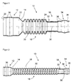
- FIG. 1 shows a sectional view of an embodiment of a corrugated hose according to the invention 10.
- the illustrated corrugated hose 10 is formed along its entire longitudinal extent tubular with a circular cross-section.
- the corrugated tube 10 has a left unwoven end portion 12, a transition portion 14, a middle corrugated portion 16 and a right non-corrugated end portion 18.
- the left end portion 12 has an interior volume 20 with a minimum cross sectional area 22 (shown schematically by line 22), which here is about 1.55 times a largest cross sectional area 24 (shown schematically by line 24) of the interior volume 26 of the corrugated portion 16 is.
- the ratio of the smallest inner diameter of the left end portion 12 to the largest inner diameter of the central corrugated portion 16 is about 1.245.
- the end section 18 has a first section 32 adjoining the central section 16 with an inner diameter and outer diameter substantially constant along the entire extension of the first section 32.
- a second partial section 34 adjoining the first partial section 32 comprises corrugated tube sections 36, which are tapered or conically widening in the direction of the right end of the corrugated tube 10.
- the left end portion 12 has corrugated tube portions 36 which are tapered conically or conically widening in the direction of the left end of the corrugated tube 10.
- FIG. 2 shows a schematic representation of another embodiment of the corrugated hose 10 according to the invention.
- the corrugated hose 10 shown here has a corrugated central portion 16 which has a cohesively formed recess 28 which is in the form of an elongated spiral whose longitudinal axis coincides with the longitudinal axis 30 of Corrugated tube 10 covers.
- the left end portion 12 has a relation to the other areas of the corrugated pipe 10 enlarged inner diameter.
Landscapes
- Engineering & Computer Science (AREA)
- General Engineering & Computer Science (AREA)
- Mechanical Engineering (AREA)
- Architecture (AREA)
- Civil Engineering (AREA)
- Structural Engineering (AREA)
- Chemical & Material Sciences (AREA)
- Combustion & Propulsion (AREA)
- Rigid Pipes And Flexible Pipes (AREA)
Applications Claiming Priority (1)
| Application Number | Priority Date | Filing Date | Title |
|---|---|---|---|
| DE200820003519 DE202008003519U1 (de) | 2008-03-12 | 2008-03-12 | Wellschlauch aus Kunststoffmaterial zur Ummantelung von wenigstens einem Abgassensor-Kabel |
Publications (2)
| Publication Number | Publication Date |
|---|---|
| EP2101095A2 true EP2101095A2 (fr) | 2009-09-16 |
| EP2101095A3 EP2101095A3 (fr) | 2013-07-17 |
Family
ID=40793064
Family Applications (1)
| Application Number | Title | Priority Date | Filing Date |
|---|---|---|---|
| EP09001804.5A Withdrawn EP2101095A3 (fr) | 2008-03-12 | 2009-02-10 | Tuyau ondulé en matière plastique destiné à gainer au moins un câble de capteur de gaz d'échappement |
Country Status (2)
| Country | Link |
|---|---|
| EP (1) | EP2101095A3 (fr) |
| DE (1) | DE202008003519U1 (fr) |
Cited By (3)
| Publication number | Priority date | Publication date | Assignee | Title |
|---|---|---|---|---|
| CN103084455A (zh) * | 2013-02-17 | 2013-05-08 | 扬中申扬换热设备有限公司 | 波纹管一次成型加工方法 |
| EP2940814A4 (fr) * | 2012-12-25 | 2016-08-24 | Yazaki Corp | Faisceau de câbles |
| CN114729716A (zh) * | 2019-11-14 | 2022-07-08 | 纽珀有限公司 | 软管装置和用于构成软管连接的方法 |
Families Citing this family (1)
| Publication number | Priority date | Publication date | Assignee | Title |
|---|---|---|---|---|
| DE102023130990A1 (de) * | 2023-11-08 | 2025-05-08 | Elringklinger Ag | Schlauch und Verfahren zum Herstellen eines Schlauchs |
Family Cites Families (8)
| Publication number | Priority date | Publication date | Assignee | Title |
|---|---|---|---|---|
| FR2533996A3 (fr) * | 1982-10-04 | 1984-04-06 | Caoutchouc Manuf Plastique | Tuyau souple de raccordement pour les circuits de fluides des vehicules |
| WO1995016873A1 (fr) * | 1993-12-16 | 1995-06-22 | Firma 2H-Kunststoffe | Raccord de tuyaux |
| DE29504100U1 (de) * | 1995-03-09 | 1995-08-24 | Siebe Automotive (Deutschland) GmbH, 89601 Schelklingen | Kunststoffrohr mit variierenden Schichtdicken |
| DE59903752D1 (de) * | 1998-04-29 | 2003-01-23 | Chemspeed Ltd | Kunststoffrohr |
| WO2001004531A1 (fr) * | 1999-07-09 | 2001-01-18 | Textiles Coated Incorporated | Conduit flexible et procede de fabrication correspondant |
| CN1226544C (zh) * | 2000-03-03 | 2005-11-09 | 丰田合成株式会社 | 燃料用树脂软管及其制造方法 |
| AU2001212066A1 (en) * | 2000-10-13 | 2002-04-29 | Oem/Miller Division Of Holm Industries | Dual wall co-extruded corrugated tubing |
| ATE371156T1 (de) * | 2000-11-23 | 2007-09-15 | Babcock Borsig Service Gmbh | Wärmetauscher für den indirekten wärmeaustausch |
-
2008
- 2008-03-12 DE DE200820003519 patent/DE202008003519U1/de not_active Expired - Lifetime
-
2009
- 2009-02-10 EP EP09001804.5A patent/EP2101095A3/fr not_active Withdrawn
Cited By (4)
| Publication number | Priority date | Publication date | Assignee | Title |
|---|---|---|---|---|
| EP2940814A4 (fr) * | 2012-12-25 | 2016-08-24 | Yazaki Corp | Faisceau de câbles |
| US10286857B2 (en) | 2012-12-25 | 2019-05-14 | Yazaki Corporation | Wire harness |
| CN103084455A (zh) * | 2013-02-17 | 2013-05-08 | 扬中申扬换热设备有限公司 | 波纹管一次成型加工方法 |
| CN114729716A (zh) * | 2019-11-14 | 2022-07-08 | 纽珀有限公司 | 软管装置和用于构成软管连接的方法 |
Also Published As
| Publication number | Publication date |
|---|---|
| EP2101095A3 (fr) | 2013-07-17 |
| DE202008003519U1 (de) | 2009-07-30 |
Similar Documents
| Publication | Publication Date | Title |
|---|---|---|
| EP2002162B1 (fr) | Conduite a fluide et tuyau flexible pour une conduite a fluide | |
| DE69514645T2 (de) | Prozess zur herstellung von gewellten mehrschicht-rohren | |
| DE4206096A1 (de) | Koaxialrohr | |
| DE60316979T2 (de) | Schlauchförmiges glied mit einem aus mehreren metalldrähten oder -röhren bestehenden umfang | |
| EP2101095A2 (fr) | Tuyau ondulé en matière plastique destiné à gainer au moins un câble de capteur de gaz d'échappement | |
| WO2017190823A1 (fr) | Procédé de fabrication d'un élément de raccordement tubulaire cintré | |
| EP1108941B1 (fr) | Raccord de tuyaux particulièrement pour conduites de carburant | |
| DD298542A5 (de) | Rohrkupplung | |
| DE2042031A1 (de) | Verfahren und Vorrichtung zur Herstellung von Wellrohren aus thermoplastischem Kunststoff | |
| DE69834935T2 (de) | Extruder zur herstellung eines ptfe-rohres | |
| EP2014439B1 (fr) | Procédé destiné à la fabrication d'un corps de soupape en plastique | |
| EP3124199B1 (fr) | Douille de calibrage reglable en continu pour tuyaux en matiere plastique extrudes | |
| EP1963761B1 (fr) | Conduite à fluide souple et son procédé de fabrication | |
| DE4224743C1 (de) | Kabelschutzrohr | |
| EP4146970B1 (fr) | Flexible, dispositif de flexible et procédé correspondant pour la fabrication d'un dispositif de flexible | |
| DE202008013047U1 (de) | Beheizbarer Schlauch | |
| DE2809266C3 (de) | Vorrichtung zur Herstellung einer Koaxialkabelseele | |
| EP2061638B1 (fr) | Procédé de fabrication de tuyaux composés en metal et plastique | |
| DE102009039972A1 (de) | Mehrkanalschlauch | |
| DE19516830A1 (de) | Preßwerkzeuge und Verfahren zum Verbinden von rohrförmigen Elementen | |
| CH703688B1 (de) | Verfahren zur Herstellung eines metallverstärkten Kunststoff-Verbundrohrs und metallverstärktes Kunststoff-Verbundrohr. | |
| EP1835216B1 (fr) | Tuyau électriquement conducteur en plastique pour véhicule | |
| EP0985867B1 (fr) | Tuyau ondulé en plastique et combinaison de ce tuyau avec un manchon | |
| DE19925097A1 (de) | Verbundrohr mit PVDC-Innenschicht | |
| DE102016119604A1 (de) | Kabelummantelung und Kabelbaum |
Legal Events
| Date | Code | Title | Description |
|---|---|---|---|
| PUAI | Public reference made under article 153(3) epc to a published international application that has entered the european phase |
Free format text: ORIGINAL CODE: 0009012 |
|
| AK | Designated contracting states |
Kind code of ref document: A2 Designated state(s): AT BE BG CH CY CZ DE DK EE ES FI FR GB GR HR HU IE IS IT LI LT LU LV MC MK MT NL NO PL PT RO SE SI SK TR |
|
| AX | Request for extension of the european patent |
Extension state: AL BA RS |
|
| PUAL | Search report despatched |
Free format text: ORIGINAL CODE: 0009013 |
|
| AK | Designated contracting states |
Kind code of ref document: A3 Designated state(s): AT BE BG CH CY CZ DE DK EE ES FI FR GB GR HR HU IE IS IT LI LT LU LV MC MK MT NL NO PL PT RO SE SI SK TR |
|
| AX | Request for extension of the european patent |
Extension state: AL BA RS |
|
| RIC1 | Information provided on ipc code assigned before grant |
Ipc: F16L 11/15 20060101ALI20130611BHEP Ipc: F16L 11/11 20060101AFI20130611BHEP |
|
| 17P | Request for examination filed |
Effective date: 20140109 |
|
| RBV | Designated contracting states (corrected) |
Designated state(s): AT BE BG CH CY CZ DE DK EE ES FI FR GB GR HR HU IE IS IT LI LT LU LV MC MK MT NL NO PL PT RO SE SI SK TR |
|
| AKX | Designation fees paid |
Designated state(s): AT BE BG CH CY CZ DE DK EE ES FI FR GB GR HR HU IE IS IT LI LT LU LV MC MK MT NL NO PL PT RO SE SI SK TR |
|
| 17Q | First examination report despatched |
Effective date: 20140319 |
|
| STAA | Information on the status of an ep patent application or granted ep patent |
Free format text: STATUS: THE APPLICATION IS DEEMED TO BE WITHDRAWN |
|
| 18D | Application deemed to be withdrawn |
Effective date: 20140730 |