EP2101135A2 - Wärmetauscher, insbesondere für Wärmegeneratoren - Google Patents
Wärmetauscher, insbesondere für Wärmegeneratoren Download PDFInfo
- Publication number
- EP2101135A2 EP2101135A2 EP09001122A EP09001122A EP2101135A2 EP 2101135 A2 EP2101135 A2 EP 2101135A2 EP 09001122 A EP09001122 A EP 09001122A EP 09001122 A EP09001122 A EP 09001122A EP 2101135 A2 EP2101135 A2 EP 2101135A2
- Authority
- EP
- European Patent Office
- Prior art keywords
- heat exchanger
- secondary fluid
- heat
- though
- exclusively
- Prior art date
- Legal status (The legal status is an assumption and is not a legal conclusion. Google has not performed a legal analysis and makes no representation as to the accuracy of the status listed.)
- Ceased
Links
Images


Classifications
-
- F—MECHANICAL ENGINEERING; LIGHTING; HEATING; WEAPONS; BLASTING
- F28—HEAT EXCHANGE IN GENERAL
- F28D—HEAT-EXCHANGE APPARATUS, NOT PROVIDED FOR IN ANOTHER SUBCLASS, IN WHICH THE HEAT-EXCHANGE MEDIA DO NOT COME INTO DIRECT CONTACT
- F28D7/00—Heat-exchange apparatus having stationary tubular conduit assemblies for both heat-exchange media, the media being in contact with different sides of a conduit wall
- F28D7/0058—Heat-exchange apparatus having stationary tubular conduit assemblies for both heat-exchange media, the media being in contact with different sides of a conduit wall the conduits for only one medium being tubes having different orientations to each other or crossing the conduit for the other heat exchange medium
-
- F—MECHANICAL ENGINEERING; LIGHTING; HEATING; WEAPONS; BLASTING
- F24—HEATING; RANGES; VENTILATING
- F24H—FLUID HEATERS, e.g. WATER OR AIR HEATERS, HAVING HEAT-GENERATING MEANS, e.g. HEAT PUMPS, IN GENERAL
- F24H1/00—Water heaters, e.g. boilers, continuous-flow heaters or water-storage heaters
- F24H1/22—Water heaters other than continuous-flow or water-storage heaters, e.g. water heaters for central heating
- F24H1/24—Water heaters other than continuous-flow or water-storage heaters, e.g. water heaters for central heating with water mantle surrounding the combustion chamber or chambers
- F24H1/26—Water heaters other than continuous-flow or water-storage heaters, e.g. water heaters for central heating with water mantle surrounding the combustion chamber or chambers the water mantle forming an integral body
- F24H1/28—Water heaters other than continuous-flow or water-storage heaters, e.g. water heaters for central heating with water mantle surrounding the combustion chamber or chambers the water mantle forming an integral body including one or more furnace or fire tubes
- F24H1/287—Water heaters other than continuous-flow or water-storage heaters, e.g. water heaters for central heating with water mantle surrounding the combustion chamber or chambers the water mantle forming an integral body including one or more furnace or fire tubes with the fire tubes arranged in line with the combustion chamber
-
- F—MECHANICAL ENGINEERING; LIGHTING; HEATING; WEAPONS; BLASTING
- F24—HEATING; RANGES; VENTILATING
- F24H—FLUID HEATERS, e.g. WATER OR AIR HEATERS, HAVING HEAT-GENERATING MEANS, e.g. HEAT PUMPS, IN GENERAL
- F24H8/00—Fluid heaters characterised by means for extracting latent heat from flue gases by means of condensation
-
- F—MECHANICAL ENGINEERING; LIGHTING; HEATING; WEAPONS; BLASTING
- F24—HEATING; RANGES; VENTILATING
- F24H—FLUID HEATERS, e.g. WATER OR AIR HEATERS, HAVING HEAT-GENERATING MEANS, e.g. HEAT PUMPS, IN GENERAL
- F24H9/00—Details
- F24H9/0005—Details for water heaters
- F24H9/001—Guiding means
- F24H9/0026—Guiding means in combustion gas channels
-
- F—MECHANICAL ENGINEERING; LIGHTING; HEATING; WEAPONS; BLASTING
- F24—HEATING; RANGES; VENTILATING
- F24H—FLUID HEATERS, e.g. WATER OR AIR HEATERS, HAVING HEAT-GENERATING MEANS, e.g. HEAT PUMPS, IN GENERAL
- F24H9/00—Details
- F24H9/16—Arrangements for water drainage
- F24H9/17—Means for retaining water leaked from heaters
-
- F—MECHANICAL ENGINEERING; LIGHTING; HEATING; WEAPONS; BLASTING
- F28—HEAT EXCHANGE IN GENERAL
- F28D—HEAT-EXCHANGE APPARATUS, NOT PROVIDED FOR IN ANOTHER SUBCLASS, IN WHICH THE HEAT-EXCHANGE MEDIA DO NOT COME INTO DIRECT CONTACT
- F28D7/00—Heat-exchange apparatus having stationary tubular conduit assemblies for both heat-exchange media, the media being in contact with different sides of a conduit wall
-
- F—MECHANICAL ENGINEERING; LIGHTING; HEATING; WEAPONS; BLASTING
- F28—HEAT EXCHANGE IN GENERAL
- F28D—HEAT-EXCHANGE APPARATUS, NOT PROVIDED FOR IN ANOTHER SUBCLASS, IN WHICH THE HEAT-EXCHANGE MEDIA DO NOT COME INTO DIRECT CONTACT
- F28D7/00—Heat-exchange apparatus having stationary tubular conduit assemblies for both heat-exchange media, the media being in contact with different sides of a conduit wall
- F28D7/16—Heat-exchange apparatus having stationary tubular conduit assemblies for both heat-exchange media, the media being in contact with different sides of a conduit wall the conduits being arranged in parallel spaced relation
- F28D7/1684—Heat-exchange apparatus having stationary tubular conduit assemblies for both heat-exchange media, the media being in contact with different sides of a conduit wall the conduits being arranged in parallel spaced relation the conduits having a non-circular cross-section
-
- F—MECHANICAL ENGINEERING; LIGHTING; HEATING; WEAPONS; BLASTING
- F28—HEAT EXCHANGE IN GENERAL
- F28F—DETAILS OF HEAT-EXCHANGE AND HEAT-TRANSFER APPARATUS, OF GENERAL APPLICATION
- F28F1/00—Tubular elements; Assemblies of tubular elements
- F28F1/02—Tubular elements of cross-section which is non-circular
-
- F—MECHANICAL ENGINEERING; LIGHTING; HEATING; WEAPONS; BLASTING
- F28—HEAT EXCHANGE IN GENERAL
- F28F—DETAILS OF HEAT-EXCHANGE AND HEAT-TRANSFER APPARATUS, OF GENERAL APPLICATION
- F28F1/00—Tubular elements; Assemblies of tubular elements
- F28F1/02—Tubular elements of cross-section which is non-circular
- F28F1/06—Tubular elements of cross-section which is non-circular crimped or corrugated in cross-section
-
- F—MECHANICAL ENGINEERING; LIGHTING; HEATING; WEAPONS; BLASTING
- F24—HEATING; RANGES; VENTILATING
- F24H—FLUID HEATERS, e.g. WATER OR AIR HEATERS, HAVING HEAT-GENERATING MEANS, e.g. HEAT PUMPS, IN GENERAL
- F24H1/00—Water heaters, e.g. boilers, continuous-flow heaters or water-storage heaters
- F24H1/18—Water-storage heaters
- F24H1/20—Water-storage heaters with immersed heating elements, e.g. electric elements or furnace tubes
- F24H1/205—Water-storage heaters with immersed heating elements, e.g. electric elements or furnace tubes with furnace tubes
-
- F—MECHANICAL ENGINEERING; LIGHTING; HEATING; WEAPONS; BLASTING
- F28—HEAT EXCHANGE IN GENERAL
- F28F—DETAILS OF HEAT-EXCHANGE AND HEAT-TRANSFER APPARATUS, OF GENERAL APPLICATION
- F28F2210/00—Heat exchange conduits
- F28F2210/06—Heat exchange conduits having walls comprising obliquely extending corrugations, e.g. in the form of threads
-
- Y—GENERAL TAGGING OF NEW TECHNOLOGICAL DEVELOPMENTS; GENERAL TAGGING OF CROSS-SECTIONAL TECHNOLOGIES SPANNING OVER SEVERAL SECTIONS OF THE IPC; TECHNICAL SUBJECTS COVERED BY FORMER USPC CROSS-REFERENCE ART COLLECTIONS [XRACs] AND DIGESTS
- Y02—TECHNOLOGIES OR APPLICATIONS FOR MITIGATION OR ADAPTATION AGAINST CLIMATE CHANGE
- Y02B—CLIMATE CHANGE MITIGATION TECHNOLOGIES RELATED TO BUILDINGS, e.g. HOUSING, HOUSE APPLIANCES OR RELATED END-USER APPLICATIONS
- Y02B30/00—Energy efficient heating, ventilation or air conditioning [HVAC]
Definitions
- the present invention relates to a heat exchanger, particularly for thermal generators.
- Tube sheet heat exchangers in which one of the fluid is caused to pass in the tubes, usually of a circular cross-section, whereas the other fluid is caused to pass outside of said tubes, in a specifically designed chamber, the so-called “mantle”, are already known.
- the aim of the present invention is to provide a high thermal exchange efficiency heat exchanger.
- a main object of the invention is to provide such a heat exchanger allowing to make very compact boiler bodies.
- a further object of the invention is to provide such a heat exchanger allowing to recover the vaporizing latent heat of combustion (condensing) fumes, in the most part of the installing and operating conditions.
- Yet another object of the present invention is to provide such a heat exchanger so constructed as to allow to directly build-in in said heat exchanger a burner, while cooling the combustion chamber by the secondary fluid, to greatly reduce the NOx emissions.
- Yet another object of the present invention is to provide such a heat exchanger having a small heat exchanger mass, thereby allowing to further reduce the overall thermal inertia, to provide a high response speed to thermal load variations and a great reduction of undesired thermal losses.
- Yet another object of the present invention is to provide such a heat exchanger allowing to greatly automatize the making process therefor, and this owing to its specifically designed mechanical construction.
- Yet another object of the present invention is to provide such a heat exchanger having a small load loss on the secondary fluid side, with a consequent great reduction of the electrical consume of the fluid driving elements (such as pumps and the like).
- Yet another object of the present invention is to provide such a heat exchanger which, owing to its specifically designed constructional features, is very reliable and safe in operation.
- a heat exchanger particular for thermal generators, characterized in that said heat exchanger comprises a plurality of heat exchanger tubes, each of said heat exchanger tubes having a multiple-lobe cross-section.
- the heat exchanger according to the present invention which has been generally indicated by the reference number 1, comprises a plurality of heat exchanger tubes having a multiple-lobe cross-section, indicated by the reference number 2, therethrough a primary fluid is caused to pass, and being associated with two perforated elements, that is a top perforated element 3 and a bottom perforated element 4.
- Said tubes are associated with said perforated elements, constituted by bottom and/or plate elements, by welding, or a like coupling process and/or by a mechanical type of coupling.
- each said heat exchanger tube 2 has a four-lobe or four-leaf cross-section.
- the tube sheet construction is so made as to arrange the heat exchanger tubes in a spoke-like configuration, so that said tube are preferably, though not necessarily, diverging from one another, as clearly shown in figures 1 and 2 .
- the thus made tube sheet is arranged in an envelope or shell 5, preferably though not exclusively of a metal material, having preferably, though not exclusively, a circular, oval or elliptic bottom, thereby it forms a single body and being provided with two or more openings, indicated by the reference numbers 6 and 7, respectively for an inlet and an outlet of a secondary fluid.
- said secondary fluid is caused to flow in said shell 5 and circulate through said inlets/outlets or outputs 6 and 7 preferably, though not exclusively, by outer mechanical means, thereby said secondary fluid is adapted to contact, from the bottom to the top, at a suitably designed flow rate, the outer part of the tube sheet, inside of which the primary fluid is caused to circulate.
- the comparatively large passage cross-section provided for the secondary fluid allows to achieve a low raising rate or speed of said secondary fluid, with an optimal thermal exchange on all the tubes 2 forming the inventive heat exchanger.
- said heat exchanger tubes 2 have a four-lobe or four-leaf cross-section, including four-lobes 21, either of a symmetrical or of an asymmetrical configuration, arranged as a crown about a central hollow body 22, and having preferably, though not exclusive, a circular cross-section.
- Figure 3 shows, in an exemplary and not limitative manner, a possible embodiment of the above mentioned cross-section, while, however, may have any desired conceptually similar pattern or configuration, but with different lobe patterns and size and with a different central body, depending on the thermal exchanger application and on the fluid thermal exchange requirements.
- the heat exchanger tubes 2 constituting the inventive heat exchanger are made by a simultaneous translation and rotation of the above mentioned four-lobe cross-section on its main axis.
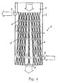
- the thus obtained tube geometry or configuration, shown in figure 4 can be considered as a four-lobe base coil, rectilinearly extending through the space.
- the specifically designed four-lobe configuration, and its coil pattern as above disclosed allows to achieve a large turbulence of the gaseous primary fluid circulating in the heat exchanger tubes as well as a high contact surface with the secondary fluid for unit length.
- the tube sheet construction is so made, moreover, that the heat exchanger tubes 2 are preferably, though not exclusively, diverging from one another, thereby allowing to provide, in a very construction-wise simple manner, the plate or top bottom 3 of the heat exchanger with a slight upward directed convexity, as is shown in figure 5 .
- Figure 5 schematically shows air bubbles 8 which are laterally ejected owing to the convexity of the bottom 3.
- the specifically designed pattern of the inventive heat exchanger allows to directly build-in in the top of the heat exchanger body one or more premixed, blown, catalytic burners for gaseous, solid and liquid fuels.
- the top portion of the heat exchanger operates as a combustion chamber with combustion chamber walls which are directly cooled by the secondary fluid.
- FIG. 6 schematically shows the arrangement of the burner, generally indicated by the reference number 9.
- the direct cooling of the combustion chamber walls can efficiently hinder a generation of thermal NOx, during the combustion process, thereby allowing to advantageously reduce the emission of polluting materials from the heat generator.
- FIG. 7 schematically shows a heat exchanger, generally indicated by the reference number 100, including the heat exchanger according to the present invention.
- the overall construction of the heat exchanger 1, coupled to a burner either of a premixed, blown or catalytic type 9, allows to make a condensation heat generator 100 which can be operated with very high temperature differences in the secondary fluid and/or different secondary fluid inlet temperatures.
- Such a mode of operation in addition to providing a very great advantage with respect to a system use flexibility, allows to easily recover fume vaporization latent heat (combustion fume condensation), with a consequent very high thermal yield efficiency, in the most part of the installing and operating condition.
- the above disclosed heat exchanger can be constructed starting from different construction materials, depending on its application but, preferably, though not exclusively, being made of stainless steel, other steel materials, copper, aluminium, plastic materials and so on.
- the inventive heat exchanger has been specifically, though not exclusively, be used in thermal generators for heating and/or generating sanitary use hot water.
- the possibility of achieving an efficient thermal exchange between a gaseous fluid and a liquid fluid, while providing a high turbulence of the first fluid, a large contact surface with the secondary fluid, and an efficient thermal exchange and a very good deaeration of the secondary fluid and the possibility of directly mounting at the top of the heat exchanger body a burner makes the inventive heat exchanger specifically suitable to be used in boilers, preferably, though not exclusively, designed for providing hot water for heating purposes, as well as for hygienic-sanitary uses.
- this heat exchanger allows it to be used in heat generators including either premixed, blown, or catalytic burners, operating on gaseous, solid and liquid fuels.
- inventive heat exchanger makes the latter suitable for use in different types of heat generators, such as conventional generators, condensation generators, and so on.
- the invention has provided a heat exchanger the constructional features of which provide a lot of advantages.
- the inventive heat exchanger has a very high thermal exchange efficiency, owing to the high turbulence of the gaseous fluid due to the fourth-lobe cross-section tubes and a very large fluid contact surface.
- the heat exchanger according to the present invention allows to use boiler bodies of a very compact size, also due to the large surface for length unit of the tube sheet.
- the heat exchanger according to the present invention allows to handle a secondary fluid very great volume, with a consequent low speed of said fluid through said exchanger and a very good thermal exchange of all the tubes forming the heat exchanger.
- inventive heat exchanger is adapted to operate with high temperature differences of the secondary fluid and/or different secondary fluid inlet temperatures.
- Yet another advantage is the possibility of recovering the vaporization latent heat of the combustion (condensation) fumes in the most part of the installing and operating conditions.
- Yet another advantage of the inventive heat exchanger is the possibility of directly associating with the heat exchanger a burner, while cooling the combustion chamber by the secondary fluid and greatly reducing the NOx emissions.
- the inventive heat exchanger has a reduced mass, allowing to consequently reduce the overall thermal inertia, while assuring a high response speed to thermal load variations and a great reduction of undesired thermal losses.
- Yet another advantage of the inventive heat exchanger is the possibility of highly automatizing its making process, owing to the particular mechanical construction of the heat exchanger.
- the inventive heat exchanger has a very small load loss on the secondary fluid side, with a consequent great reduction of the electrical consume of the fluid driving elements (such as pumps and the like).
- the used materials, as well as the contingent size and shapes can be any, depending on requirements.
Landscapes
- Engineering & Computer Science (AREA)
- Physics & Mathematics (AREA)
- Thermal Sciences (AREA)
- Mechanical Engineering (AREA)
- General Engineering & Computer Science (AREA)
- Chemical & Material Sciences (AREA)
- Combustion & Propulsion (AREA)
- Geometry (AREA)
- Heat-Exchange Devices With Radiators And Conduit Assemblies (AREA)
Applications Claiming Priority (1)
| Application Number | Priority Date | Filing Date | Title |
|---|---|---|---|
| IT000408A ITMI20080408A1 (it) | 2008-03-10 | 2008-03-10 | Scambiatore di calore, particolarmente per generatori termici. |
Publications (2)
| Publication Number | Publication Date |
|---|---|
| EP2101135A2 true EP2101135A2 (de) | 2009-09-16 |
| EP2101135A3 EP2101135A3 (de) | 2010-10-27 |
Family
ID=40292868
Family Applications (1)
| Application Number | Title | Priority Date | Filing Date |
|---|---|---|---|
| EP20090001122 Ceased EP2101135A3 (de) | 2008-03-10 | 2009-01-28 | Wärmetauscher, insbesondere für Wärmegeneratoren |
Country Status (5)
| Country | Link |
|---|---|
| US (1) | US8783334B2 (de) |
| EP (1) | EP2101135A3 (de) |
| CN (1) | CN101532791B (de) |
| IT (1) | ITMI20080408A1 (de) |
| RU (1) | RU2472087C2 (de) |
Cited By (5)
| Publication number | Priority date | Publication date | Assignee | Title |
|---|---|---|---|---|
| EP2806231A4 (de) * | 2012-01-19 | 2015-06-24 | Sung-Hwan Choi | Kondensierungskessel mit einem heisswasserspeichertank und einer mehrebenenstruktur |
| CN105466248A (zh) * | 2016-01-14 | 2016-04-06 | 佛山市金银河智能装备股份有限公司 | 一种管壳式冷却器 |
| EP3058303A1 (de) * | 2013-10-02 | 2016-08-24 | Intergas Heating Assets B.V. | Röhre für einen wärmetauscher mit zumindest teilweise variablem querschnitt und damit ausgestatteter wärmetauscher |
| WO2017007352A1 (en) * | 2015-07-05 | 2017-01-12 | Aic Społka Akcyjna | Tube heat exchanger casing |
| EP3136014A4 (de) * | 2014-04-22 | 2017-12-27 | Young-Hwan Choi | Wärmetauscher mit kreislaufführung |
Families Citing this family (12)
| Publication number | Priority date | Publication date | Assignee | Title |
|---|---|---|---|---|
| GB2484286B (en) * | 2010-10-04 | 2014-10-29 | Johnson & Starley Ltd | Heat exchanger |
| JP2013083371A (ja) * | 2011-10-06 | 2013-05-09 | Hitachi Industrial Equipment Systems Co Ltd | スクリュー圧縮機 |
| US20130091836A1 (en) * | 2011-10-14 | 2013-04-18 | Sustainx, Inc. | Dead-volume management in compressed-gas energy storage and recovery systems |
| KR101676271B1 (ko) * | 2013-06-27 | 2016-11-16 | 이래오토모티브시스템 주식회사 | 중공 구조 하우징을 포함하는 열교환기 |
| KR101938398B1 (ko) * | 2016-03-28 | 2019-01-15 | 주식회사 경동나비엔 | 관체형 열교환기 |
| US20180164047A1 (en) * | 2016-12-13 | 2018-06-14 | Hafez Raeisi Fard | Heat exchanger including twisted tubes |
| US20180372413A1 (en) * | 2017-06-22 | 2018-12-27 | Rheem Manufacturing Company | Heat Exchanger Tubes And Tube Assembly Configurations |
| KR102428535B1 (ko) * | 2017-12-29 | 2022-08-03 | 주식회사 경동나비엔 | 연관식 보일러 |
| KR102120117B1 (ko) * | 2018-11-23 | 2020-06-09 | 주식회사 귀뚜라미 | 경사형 화실을 가지는 저탕식 보일러 |
| KR102372925B1 (ko) * | 2019-05-03 | 2022-03-11 | 주식회사 경동나비엔 | 오일 보일러 |
| US20210356169A1 (en) * | 2020-05-13 | 2021-11-18 | Beckett Thermal Solutions | Heat exchanger for water heater |
| CN117404838A (zh) * | 2023-11-08 | 2024-01-16 | 浙江康盛科工贸有限公司 | 低温液化气冷量回收系统 |
Family Cites Families (25)
| Publication number | Priority date | Publication date | Assignee | Title |
|---|---|---|---|---|
| FR345722A (fr) * | 1904-08-02 | 1904-12-09 | Robert Charles Monteagle | Tube conducteur de la chaleur et du froid |
| US1352802A (en) * | 1919-07-25 | 1920-09-14 | Louis F Faust | Water-heater |
| US1550402A (en) * | 1924-04-23 | 1925-08-18 | Ingersoll Rand Co | Surface condenser |
| US2053590A (en) * | 1930-08-18 | 1936-09-08 | Frank A Whiteley | Furnace |
| US2153361A (en) * | 1938-11-23 | 1939-04-04 | Gen Electric | Surface condenser |
| US2470936A (en) * | 1944-04-13 | 1949-05-24 | Gerfo Salvatore Lo | Apparatus for chilling fluids |
| US2874683A (en) * | 1955-01-28 | 1959-02-24 | Kaiser Aluminium Chem Corp | Hot water tank flue construction |
| US2994307A (en) * | 1960-03-03 | 1961-08-01 | Yuba Cons Ind Inc | Vertical tube heater |
| US3578075A (en) * | 1969-10-29 | 1971-05-11 | Olin Corp | Corrugated tubing |
| US4207944A (en) * | 1978-02-15 | 1980-06-17 | Joseph Oat Corporation | Heat exchanger for withstanding cyclic changes in temperature |
| JPS59501171A (ja) * | 1982-06-29 | 1984-07-05 | アラーズ ヴェルクステッダー アーベー | チユ−ブ式熱交換器 |
| GB8428166D0 (en) * | 1984-11-07 | 1984-12-12 | British Gas Corp | Gas-fired water heaters |
| SU1283244A1 (ru) * | 1985-08-07 | 1987-01-15 | Центральное конструкторское бюро нефтеаппаратуры | Вертикальна цилиндрическа трубчата печь |
| US5067330A (en) * | 1990-02-09 | 1991-11-26 | Columbia Gas System Service Corporation | Heat transfer apparatus for heat pumps |
| US5181560A (en) * | 1990-10-17 | 1993-01-26 | Burn Mark N | Baffleless tube and shell heat exchanger having fluted tubes |
| US5251693A (en) * | 1992-10-19 | 1993-10-12 | Zifferer Lothar R | Tube-in-shell heat exchanger with linearly corrugated tubing |
| US5573062A (en) * | 1992-12-30 | 1996-11-12 | The Furukawa Electric Co., Ltd. | Heat transfer tube for absorption refrigerating machine |
| US5409057A (en) * | 1993-01-22 | 1995-04-25 | Packless Metal Hose, Inc. | Heat exchange element |
| RU2036377C1 (ru) * | 1993-12-07 | 1995-05-27 | Государственно-кооперативный институт "Мособлинжпроект" | Котельная установка для автономных систем теплоснабжения |
| EP0926439A3 (de) * | 1997-12-23 | 2000-07-12 | Renato Montini | Gasheizkessel |
| RU2137052C1 (ru) * | 1998-04-06 | 1999-09-10 | Мельниченко Владимир Акимович | Теплогенератор "рязань-3" |
| IT247800Y1 (it) * | 1999-12-02 | 2002-09-10 | R I Stampi Articoli Ind Di Zen | Componente per scambiatore di calore liquido/aeriforme |
| US6488079B2 (en) * | 2000-12-15 | 2002-12-03 | Packless Metal Hose, Inc. | Corrugated heat exchanger element having grooved inner and outer surfaces |
| US7213639B2 (en) * | 2005-03-16 | 2007-05-08 | Detroit Diesel Coporation | Heat exchanger exhaust gas recirculation cooler |
| US8162040B2 (en) * | 2006-03-10 | 2012-04-24 | Spinworks, LLC | Heat exchanging insert and method for fabricating same |
-
2008
- 2008-03-10 IT IT000408A patent/ITMI20080408A1/it unknown
-
2009
- 2009-01-28 EP EP20090001122 patent/EP2101135A3/de not_active Ceased
- 2009-02-11 US US12/378,117 patent/US8783334B2/en active Active
- 2009-03-02 RU RU2009108217/06A patent/RU2472087C2/ru active
- 2009-03-06 CN CN2009100045764A patent/CN101532791B/zh active Active
Cited By (5)
| Publication number | Priority date | Publication date | Assignee | Title |
|---|---|---|---|---|
| EP2806231A4 (de) * | 2012-01-19 | 2015-06-24 | Sung-Hwan Choi | Kondensierungskessel mit einem heisswasserspeichertank und einer mehrebenenstruktur |
| EP3058303A1 (de) * | 2013-10-02 | 2016-08-24 | Intergas Heating Assets B.V. | Röhre für einen wärmetauscher mit zumindest teilweise variablem querschnitt und damit ausgestatteter wärmetauscher |
| EP3136014A4 (de) * | 2014-04-22 | 2017-12-27 | Young-Hwan Choi | Wärmetauscher mit kreislaufführung |
| WO2017007352A1 (en) * | 2015-07-05 | 2017-01-12 | Aic Społka Akcyjna | Tube heat exchanger casing |
| CN105466248A (zh) * | 2016-01-14 | 2016-04-06 | 佛山市金银河智能装备股份有限公司 | 一种管壳式冷却器 |
Also Published As
| Publication number | Publication date |
|---|---|
| CN101532791B (zh) | 2012-07-11 |
| EP2101135A3 (de) | 2010-10-27 |
| ITMI20080408A1 (it) | 2009-09-11 |
| RU2009108217A (ru) | 2010-09-10 |
| US8783334B2 (en) | 2014-07-22 |
| US20090223655A1 (en) | 2009-09-10 |
| RU2472087C2 (ru) | 2013-01-10 |
| CN101532791A (zh) | 2009-09-16 |
Similar Documents
| Publication | Publication Date | Title |
|---|---|---|
| US8783334B2 (en) | Heat exchanger particularly for thermal generators | |
| KR20090063438A (ko) | 콘덴싱 보일러 | |
| JP2019510952A (ja) | チューブ型熱交換器 | |
| EP3021055B1 (de) | Wärmetauscher für heizkessel | |
| EP2724106B1 (de) | System von wärmetauscherröhren | |
| US9557075B2 (en) | Condensing heat exchanger and boiler/water heater including the same | |
| US11852377B2 (en) | High efficiency tankless water heater | |
| EP2943729B1 (de) | Beheizter wärmetauscher | |
| EP3287696A1 (de) | Ölbefeuerter kessel mit brenngaswegführung | |
| RU2194920C2 (ru) | Усовершенствованный конденсационный котел с предварительным смешением для систем коммунально-бытового водоснабжения и отопительных систем | |
| CN110926026A (zh) | 一种换热器及冷凝锅炉 | |
| WO2008078211A1 (en) | A heat exchanger | |
| KR200277473Y1 (ko) | 열교환기 | |
| RU2169316C1 (ru) | Отопительный котел | |
| KR100446883B1 (ko) | 가스보일러의 열교환기 | |
| KR102583907B1 (ko) | 열교환관 및 이를 포함하는 보일러 | |
| KR100515636B1 (ko) | 가스보일러의 열교환기 구조 | |
| KR100229311B1 (ko) | 2중 쉘 발생기 | |
| KR200330705Y1 (ko) | 온수보일러 | |
| GB2028985A (en) | Improvements in and relating to boilers | |
| JP3805897B2 (ja) | 多管式貫流ボイラ | |
| KR100460503B1 (ko) | 수관식 열교환기 | |
| JP2005321171A (ja) | 瞬間式加熱装置および給湯装置 | |
| KR200297429Y1 (ko) | 열풍 보일러 | |
| JPH03225164A (ja) | 直焚発生器 |
Legal Events
| Date | Code | Title | Description |
|---|---|---|---|
| PUAI | Public reference made under article 153(3) epc to a published international application that has entered the european phase |
Free format text: ORIGINAL CODE: 0009012 |
|
| AK | Designated contracting states |
Kind code of ref document: A2 Designated state(s): AT BE BG CH CY CZ DE DK EE ES FI FR GB GR HR HU IE IS IT LI LT LU LV MC MK MT NL NO PL PT RO SE SI SK TR |
|
| AX | Request for extension of the european patent |
Extension state: AL BA RS |
|
| PUAL | Search report despatched |
Free format text: ORIGINAL CODE: 0009013 |
|
| AK | Designated contracting states |
Kind code of ref document: A3 Designated state(s): AT BE BG CH CY CZ DE DK EE ES FI FR GB GR HR HU IE IS IT LI LT LU LV MC MK MT NL NO PL PT RO SE SI SK TR |
|
| AX | Request for extension of the european patent |
Extension state: AL BA RS |
|
| 17P | Request for examination filed |
Effective date: 20110325 |
|
| AKX | Designation fees paid |
Designated state(s): AT BE BG CH CY CZ DE DK EE ES FI FR GB GR HR HU IE IS IT LI LT LU LV MC MK MT NL NO PL PT RO SE SI SK TR |
|
| 17Q | First examination report despatched |
Effective date: 20150625 |
|
| STAA | Information on the status of an ep patent application or granted ep patent |
Free format text: STATUS: THE APPLICATION HAS BEEN REFUSED |
|
| 18R | Application refused |
Effective date: 20161029 |