EP2101330A1 - Dispositif à disque - Google Patents
Dispositif à disque Download PDFInfo
- Publication number
- EP2101330A1 EP2101330A1 EP09002685A EP09002685A EP2101330A1 EP 2101330 A1 EP2101330 A1 EP 2101330A1 EP 09002685 A EP09002685 A EP 09002685A EP 09002685 A EP09002685 A EP 09002685A EP 2101330 A1 EP2101330 A1 EP 2101330A1
- Authority
- EP
- European Patent Office
- Prior art keywords
- optical pickup
- inward
- bottom plate
- disk device
- respect
- Prior art date
- Legal status (The legal status is an assumption and is not a legal conclusion. Google has not performed a legal analysis and makes no representation as to the accuracy of the status listed.)
- Granted
Links
- 230000003287 optical effect Effects 0.000 claims abstract description 55
- 239000002390 adhesive tape Substances 0.000 claims description 4
- 238000003780 insertion Methods 0.000 description 6
- 230000037431 insertion Effects 0.000 description 6
- 238000005452 bending Methods 0.000 description 2
- 230000007423 decrease Effects 0.000 description 1
- 230000009977 dual effect Effects 0.000 description 1
- 238000005516 engineering process Methods 0.000 description 1
- 238000004519 manufacturing process Methods 0.000 description 1
- 238000012986 modification Methods 0.000 description 1
- 230000004048 modification Effects 0.000 description 1
Images


Classifications
-
- G—PHYSICS
- G11—INFORMATION STORAGE
- G11B—INFORMATION STORAGE BASED ON RELATIVE MOVEMENT BETWEEN RECORD CARRIER AND TRANSDUCER
- G11B17/00—Guiding record carriers not specifically of filamentary or web form, or of supports therefor
- G11B17/02—Details
- G11B17/04—Feeding or guiding single record carrier to or from transducer unit
- G11B17/05—Feeding or guiding single record carrier to or from transducer unit specially adapted for discs not contained within cartridges
- G11B17/053—Indirect insertion, i.e. with external loading means
- G11B17/056—Indirect insertion, i.e. with external loading means with sliding loading means
-
- G—PHYSICS
- G11—INFORMATION STORAGE
- G11B—INFORMATION STORAGE BASED ON RELATIVE MOVEMENT BETWEEN RECORD CARRIER AND TRANSDUCER
- G11B33/00—Constructional parts, details or accessories not provided for in the other groups of this subclass
- G11B33/12—Disposition of constructional parts in the apparatus, e.g. of power supply, of modules
- G11B33/121—Disposition of constructional parts in the apparatus, e.g. of power supply, of modules the apparatus comprising a single recording/reproducing device
- G11B33/122—Arrangements for providing electrical connections, e.g. connectors, cables, switches
-
- G—PHYSICS
- G11—INFORMATION STORAGE
- G11B—INFORMATION STORAGE BASED ON RELATIVE MOVEMENT BETWEEN RECORD CARRIER AND TRANSDUCER
- G11B7/00—Recording or reproducing by optical means, e.g. recording using a thermal beam of optical radiation by modifying optical properties or the physical structure, reproducing using an optical beam at lower power by sensing optical properties; Record carriers therefor
- G11B7/08—Disposition or mounting of heads or light sources relatively to record carriers
- G11B7/085—Disposition or mounting of heads or light sources relatively to record carriers with provision for moving the light beam into, or out of, its operative position or across tracks, otherwise than during the transducing operation, e.g. for adjustment or preliminary positioning or track change or selection
- G11B7/0857—Arrangements for mechanically moving the whole head
- G11B7/08582—Sled-type positioners
Definitions
- the present invention generally relates to a disk device. More specifically, the present invention relates to a disk device having a flexible flat cable connected to an optical pickup.
- a conventional disk device has an optical pickup and a flexible flat cable connected to the optical pickup via a connector.
- a durability test of the disk device includes a durability test of 200,000 full seek operations with the disk device. For example, a plurality of (such as four) disk devices having a 45-pin flexible flat cable are readied for test use. The optical pickup of each of the disk devices is moved back and forth 200,000 times between innermost and outermost peripheries of a disk. Then, the flexible flat cable is checked for discontinuity.
- Japanese Laid-Open Patent Application Publication No. H 11-242860 discusses related technology.
- the present invention is conceived in light of the above-mentioned problems.
- One object of the present invention is to provide a disk device in which durability of a flexible flat cable connected to an optical pickup is improved.
- a disk device in accordance with one aspect of the present invention, includes a loader chassis, a control board, an optical pickup, a flexible flat cable, and a guide member.
- the loader chassis has a bottom plate with a through hole.
- the control board is fixedly attached to a lower face of the bottom plate of the loader chassis.
- the optical pickup is movable between inner and outer positions with respect to the loadcr chassis in inward and outward movement directions that arc parallel to a radial direction of a disk disposed in the loader chassis.
- the flexible flat cable electrically connects the control board to the optical pickup and is partially disposed through the through hole of the loader chassis.
- the flexible flat cable includes a bent end portion that is connected to the optical pickup.
- the guide member is formed on an upper face of the bottom plate of the loader chassis and guides the bent end portion upward with respect to the bottom plate when the optical pickup is located at the outer position with respect to the loader chassis.
- the disk device of the present invention it is possible to provide a disk device in which durability of a flexible flat cable connected to an optical pickup is improved.
- FIG. 1 is a top plan view of a disk device in accordance with one embodiment of the present invention.
- FIG. 2 is a cross sectional view of the disk device taken along II-II line illustrated in FIG. 1 ;
- FIG. 3 is a detail cross sectional view of the disk device illustrated in FIG. 1 ;
- FIG. 4A is a perspective view of a guide member of the disk device illustrated in FIG. 1 ;
- FIG. 4B is a cross sectional view of the guide member taken along IVB-IVB line illustrated in FIG. 4A ;
- FIG. 4C is a top plan view of the guide member of the disk device illustrated in FIG. 1 ;
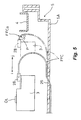
- FIG. 5 is a cross sectional view of a disk device without a guide member.
- a disk device includes a turntable 1, a spindle motor 2, an optical pickup 3, a traverse chassis 4, a loader chassis 5, an elevator 8, a cam slider 10, a cam mechanism 11, a tray 13, a clamper 19, a control board 23, and a flexible flat cable FFC.
- the disk device is an optical disk device, such as a DVD recorder, a DVD player, a BD recorder, a BD player, or the like.
- the turntable 1 is attached to the spindle motor 2.
- the optical pickup 3 includes an objective lens OL.
- the spindle motor 2 and the optical pickup 3 are mounted on the traverse chassis 4.
- the traverse chassis 4 is disposed within the loader chassis 5.
- a rear part of the traverse chassis 4 is linked via a rear elastic member 6 to the loader chassis 5 so as to be capable of up and down motion in directions along arrows a and b.
- a front part of the traverse chassis 4 is linked to the elevator 8 via a front elastic member 7.
- the rear and front elastic members 6 and 7 are made of rubber.
- the cam slider 10 has a substantially T-shaped lateral cross section.
- the cam slider 10 is disposed at a front part of the loader chassis 5 and slidable in directions along arrows c and d.
- the cam slider 10 and the elevator 8 are conjointly linked by the cam mechanism 11.
- the cam mechanism 11 includes a cam groove 11a and a cam pin 11b.
- the cam groove 11a is formed in a vertical part of the cam slider 10.
- the cam pin 11b protrudes integrally from a front face of the elevator 8 and is fitted into the cam groove 11a.
- a cam rack 10a is integrally formed at one end of the cam slider 10.
- the cam rack 10a is formed so as to mesh with a drive pinion 12.
- the drive pinion 12 rotates in directions along arrows e and f.
- the drive pinion 12 is disposed at the front part of the loader chassis 5.
- the tray 13 on which a disk D is placed is disposed at an upper part of the loader chassis 5 so as to move in directions along arrows g and h.
- a rack (not shown) is formed on a lower face of the tray 13. The rack is formed so as to mesh with the drive pinion 12.
- the optical pickup 3 When the optical pickup 3 is disposed in a center opening 4a of the traverse chassis 4, the optical pickup 3 is supported by a guide rod 1 so as to move back and forth in directions along arrows i and j.
- a toothed component 3a is provided to the optical pickup 3.
- the toothed component 3a is meshed with a lead screw 16.
- the optical pickup 3 is moved back and forth along the allows i and j in a radial direction of the disk D between innermost and outermost peripheries (e.g., between inner and outer positions) of the disk D by a feed motor 17 via the lead screw 16 and the toothed component 3a.
- the clamper 19 is disposed elevatably within a specific range in a center through-hole 20a in a transverse beam 20 spanning between side plates of the loader chassis 5.
- a plurality of legs 22 arc provided integrally protruding from a lower face of a bottom plate 5A of the loader chassis 5.
- the control board 23 is fastened by a screw 24 in each of the legs 22.
- the control board 23 includes a printed circuit board.
- a cable insertion hole 25 and a cable insertion hole (e.g., through hole) 26 are formed in a front side of the control board 23 and a center of the bottom plate 5A, respectively.
- the flexible flat cable FFC connects the control board 23 and the optical pickup 3.
- the flexible flat cable FFC is disposed through the cable insertion holes 25 and 26.
- One end of the flexible flat cable FFC is connected to the control board 23 via a connector 27, and the other end of the flexible flat cable FFC is bent back in an arc shape and connected to the optical pickup 3 via a connector 28.
- the disk D In play mode, as indicated by solid lines in FIGS. and 2, the disk D is clamped by the turntable 1 and the clamper 19. Then, the disk D is rotated at high speed by the spindle motor 2 with the turntable 1.
- the optical pickup 3 is moved back and forth in the radial direction of the disk D. Specifically, the optical pickup 3 is movable with respect to the loader chassis 5 in inward and outward movement directions parallel to the radial direction of the disk D.
- the optical pickup 3 is controlled via the flexible flat cable FFC, so that a laser beam illuminates on the disk D emitted from the objective lens OL of the optical pickup 3, and information recorded on the disk D is read based on the reflected laser beam.
- the drive pinion 12 and the cam rack 10a are unmeshed.
- the pin (not shown) of the cam slider 10 moves the tray 13 slightly in the direction of the arrow g.
- the rack (not shown) formed on the lower face of the tray 13 is meshed with the drive pinion 12.
- the tray 13 is pushed out in the direction of the arrow g as the drive pinion 12 rotates in the direction of the arrow f.
- the disk D on the tray 13 is replaced.
- the tray 13 is closed, the operation is performed in a reverse order of the above.
- a guide member 30 is integrally formed with the bottom plate 5A of the loader chassis 5 as a one-piece, unitary member.
- the guide member 30 guides an are-shaped bent-back portion (e.g., bent end portion) FFCa of the other end of the flexible flat cable FFC upward and increases a radius of curvature r2 of the bent-back portion FFCa of the other end.
- the guide member 30 includes a transverse guide plate (e.g., first guide plate) 31 and a pair of left and right longitudinal guide plates (e.g., second guide plates) 32.
- the transverse guide plate 31 is formed in a rectangular shape when viewed from a direction perpendicular to the transverse guide plate 31.
- the transverse guide plate 31 extends in a direction (e.g., transverse direction) that is perpendicular to the movement direction along the arrows i and j of the optical pickup 3.
- the left and right longitudinal guide plates 32 extend forward in the movement direction of the arrow i of the optical pickup 3 from both side edges (e.g., edge portions) of the transverse guide plate 31.
- the longitudinal guide plates 32 are substantially triangular when viewed from the side.
- the longitudinal guide plates 32 include cable-opposing faces (e.g., second upper slope faces) 32a.
- the cable-opposing faces 32a of the longitudinal guide plates 32 are tilted along an imaginary line S that extends upward from front ends of the longitudinal guide plates 32 toward the transverse guide plate 31 at a specific tilt angle ⁇ (such as 35°).
- the transverse guide plate 31 includes a tilted cable-opposing face (e.g., first upper slope face) 31 a.
- the tilted cable-opposing face 31a is formed at an upper end of the transverse guide plate 31 along the imaginary line S.
- the cable-opposing faces 31a and 32a slope downward in the movement direction of the arrow i of the optical pickup 3.
- the bent-back portion FFCa of the other end of the flexible flat cable FFC contacts with the cable-opposing faces 32a of the longitudinal guide plates 32. Then, the bent-back portion FFCa contacts with the cable-opposing face 31a of the transverse guide plate 31 as the optical pickup 3 is moved towards the outermost periphery of the disk D.
- the bent-back portion FFCa is guided and pushed upward by the cable-opposing faces 31a and 32a of the transverse and longitudinal guide plates 31 and 32.
- the radius of curvature r2 of the bent-back portion FFCa becomes larger than radius of curvature of a bent-back portion FFCa of a disk device without the guide member 30 illustrated in FIG. 5 .
- the bent-back portion FFCa of the other end of the flexible flat cable FFC is pulled downward.
- the bent-back portion FFCa is bent relatively sharply, and the radius of curvature r1 of the bent-back portion FFCa near the connector 28 is smaller.
- the radius of curvature r2 of the bent-back portion FFCa is larger than in the case of the disk device without the guide member 30.
- the bent-back portion FFCa is bent relatively gently. Accordingly, when the durability test of 200,000 full seek operations is conducted, the bending stress to which the flexible flat cable FFC is repeatedly subjected at a boundary portion P between the flexible flat cable FFC and the optical pickup 3 is less than in the case of the disk device without the guide member 30. Thus, no discontinuity occurs at the boundary portion P, and the durability of the flexible flat cable FFC can be increased.
- the bent-back portion FFCa of the other end of the flexible flat cable FFC is stably supported at three points by the cable-opposing faces 31 a and 32a of the transverse guide plate 31 and the two longitudinal guide plates 32.
- the cable-opposing faces 31a and 32a of the transverse guide plate 31 and the two longitudinal guide plates 32 are tilted along the imaginary line S extending diagonally upward at the specific tilt angle ⁇ .
- the bent-back portion FFCa of the other end of the flexible flat cable FFC can be pushed up smoothly.
- the transverse guide plate 3 extend in the direction perpendicular to the movement directions of the optical pickup 3.
- the lateral width h1 of the transverse guide plate 31 is set to be less than the lateral width h2 of the flexible flat cable FFC.
- transverse guide plate 31 and the longitudinal guide plates 32 are provided integrally protruding from the loader chassis 5. Therefore, there is no increase in the number of parts required, which lowers the manufacturing cost of the disk device.
- an outward portion of the bottom plate 5A of the loader chassis 5 located in the rear of the cable insertion hole 26 is set higher by a specific distance t (such as 4 mm) than a cable-opposing portion (e.g., inward portion) 5a of the bottom plate 5A.
- the cable-opposing portion 5a of the bottom plate 5A is located in front of the cable insertion hole 26.
- the cable-opposing portion 5a is tilted upward at a specific tilt angle ⁇ (such as 5°) toward the guide member 30. In other words, the cable-opposing portion 5a is tilted downward in the movement direction of the arrow i of the optical pickup 3 with respect to the outward portion of the bottom plate 5A.
- the flexible flat cable FFC is bonded with a double-sided adhesive tape 34 to the lower face of the tilted cable-opposing portion 5a.
- the flexible flat cable FFC can be easily routed along the tilt.
- the flexible flat cable FFC is bonded to the lower face of the tilted cable-opposing portion 5a via the double-sided adhesive tape 34, even if the flexible flat cable FFC should be subjected to excessive tensile force during assembly, for example, the ends of the flexible flat cable FFC will not be unintentionally pulled away from the connectors 27 and 28 (e.g., from the control board 23 and the optical pickup 3) by the tensile force. Accordingly, the control board 23 and the optical pickup 3 can be reliably maintained in a state of being connected by the flexible flat cable FFC.
Landscapes
- Moving Of The Head For Recording And Reproducing By Optical Means (AREA)
- Moving Of Heads (AREA)
Applications Claiming Priority (1)
| Application Number | Priority Date | Filing Date | Title |
|---|---|---|---|
| JP2008060691A JP4508250B2 (ja) | 2008-03-11 | 2008-03-11 | ディスク装置 |
Publications (2)
| Publication Number | Publication Date |
|---|---|
| EP2101330A1 true EP2101330A1 (fr) | 2009-09-16 |
| EP2101330B1 EP2101330B1 (fr) | 2011-07-20 |
Family
ID=40456297
Family Applications (1)
| Application Number | Title | Priority Date | Filing Date |
|---|---|---|---|
| EP09002685A Expired - Fee Related EP2101330B1 (fr) | 2008-03-11 | 2009-02-25 | Dispositif à disque |
Country Status (3)
| Country | Link |
|---|---|
| US (1) | US8151286B2 (fr) |
| EP (1) | EP2101330B1 (fr) |
| JP (1) | JP4508250B2 (fr) |
Cited By (1)
| Publication number | Priority date | Publication date | Assignee | Title |
|---|---|---|---|---|
| CN102959630A (zh) * | 2011-02-17 | 2013-03-06 | 松下电器产业株式会社 | 光盘驱动装置 |
Families Citing this family (6)
| Publication number | Priority date | Publication date | Assignee | Title |
|---|---|---|---|---|
| JP5624827B2 (ja) * | 2010-08-03 | 2014-11-12 | アルパイン株式会社 | ディスク装置 |
| WO2012111247A1 (fr) | 2011-02-17 | 2012-08-23 | パナソニック株式会社 | Dispositif de lecteur de disque optique et structure de câblage |
| JP5873996B2 (ja) * | 2011-02-18 | 2016-03-01 | パナソニックIpマネジメント株式会社 | 光ディスク駆動装置および配線構造 |
| JP2012230742A (ja) * | 2011-04-27 | 2012-11-22 | Funai Electric Co Ltd | 光ディスク装置 |
| CN102842315A (zh) * | 2011-06-24 | 2012-12-26 | 鸿富锦精密工业(深圳)有限公司 | 光盘播放装置 |
| JP2015125786A (ja) * | 2013-12-26 | 2015-07-06 | 船井電機株式会社 | 光ディスク装置 |
Citations (6)
| Publication number | Priority date | Publication date | Assignee | Title |
|---|---|---|---|---|
| JPH05258548A (ja) * | 1992-03-16 | 1993-10-08 | Olympus Optical Co Ltd | 光学式情報記録再生装置 |
| JPH10134412A (ja) * | 1996-10-30 | 1998-05-22 | Akai Electric Co Ltd | 記録または再生装置のピックアップ装置 |
| EP0869500A2 (fr) | 1997-04-03 | 1998-10-07 | Mitsumi Electric Company Ltd. | Mécanisme de positionnement d'une plaquette de circuit imprimé souple pour tête de lecture utilisée dans un entrainement de disques et unité de tête de lecture utilisée dans un entrainement pour disques |
| JPH1125666A (ja) * | 1997-06-27 | 1999-01-29 | Toshiba Corp | ディスク再生装置 |
| EP1607977A2 (fr) * | 2004-06-15 | 2005-12-21 | ORION ELECTRIC CO., Ltd. | Disposiif électronique avec appareil à disque intégré |
| US20070067789A1 (en) * | 2004-03-31 | 2007-03-22 | Sony Corporation | Disk drive device and base unit |
Family Cites Families (8)
| Publication number | Priority date | Publication date | Assignee | Title |
|---|---|---|---|---|
| JP2880869B2 (ja) * | 1993-02-15 | 1999-04-12 | シャープ株式会社 | 移動体の接続装置 |
| JPH10293932A (ja) * | 1997-04-17 | 1998-11-04 | Mitsumi Electric Co Ltd | 光ディスク駆動装置における光ピックアップのスキュー調整機構 |
| JP3092665B2 (ja) | 1998-12-16 | 2000-09-25 | 船井電機株式会社 | ディスクプレーヤ |
| CN1463439A (zh) * | 2001-04-10 | 2003-12-24 | 西铁成时计株式会社 | 光盘驱动装置 |
| JP3976526B2 (ja) * | 2001-07-19 | 2007-09-19 | 株式会社リコー | 光ディスクドライブ装置 |
| JP2003309381A (ja) * | 2002-04-15 | 2003-10-31 | Mitsumi Electric Co Ltd | 可撓性配線基板の配設構造 |
| JP4334544B2 (ja) * | 2006-01-27 | 2009-09-30 | 株式会社ケンウッド | ディスク装置の光ピックアップ送り機構 |
| JP4720710B2 (ja) * | 2006-10-14 | 2011-07-13 | 船井電機株式会社 | 光ピックアップ |
-
2008
- 2008-03-11 JP JP2008060691A patent/JP4508250B2/ja not_active Expired - Fee Related
-
2009
- 2009-02-19 US US12/388,615 patent/US8151286B2/en not_active Expired - Fee Related
- 2009-02-25 EP EP09002685A patent/EP2101330B1/fr not_active Expired - Fee Related
Patent Citations (6)
| Publication number | Priority date | Publication date | Assignee | Title |
|---|---|---|---|---|
| JPH05258548A (ja) * | 1992-03-16 | 1993-10-08 | Olympus Optical Co Ltd | 光学式情報記録再生装置 |
| JPH10134412A (ja) * | 1996-10-30 | 1998-05-22 | Akai Electric Co Ltd | 記録または再生装置のピックアップ装置 |
| EP0869500A2 (fr) | 1997-04-03 | 1998-10-07 | Mitsumi Electric Company Ltd. | Mécanisme de positionnement d'une plaquette de circuit imprimé souple pour tête de lecture utilisée dans un entrainement de disques et unité de tête de lecture utilisée dans un entrainement pour disques |
| JPH1125666A (ja) * | 1997-06-27 | 1999-01-29 | Toshiba Corp | ディスク再生装置 |
| US20070067789A1 (en) * | 2004-03-31 | 2007-03-22 | Sony Corporation | Disk drive device and base unit |
| EP1607977A2 (fr) * | 2004-06-15 | 2005-12-21 | ORION ELECTRIC CO., Ltd. | Disposiif électronique avec appareil à disque intégré |
Cited By (2)
| Publication number | Priority date | Publication date | Assignee | Title |
|---|---|---|---|---|
| CN102959630A (zh) * | 2011-02-17 | 2013-03-06 | 松下电器产业株式会社 | 光盘驱动装置 |
| CN102959630B (zh) * | 2011-02-17 | 2015-09-02 | 松下电器产业株式会社 | 光盘驱动装置 |
Also Published As
| Publication number | Publication date |
|---|---|
| JP2009217892A (ja) | 2009-09-24 |
| JP4508250B2 (ja) | 2010-07-21 |
| US20090235292A1 (en) | 2009-09-17 |
| EP2101330B1 (fr) | 2011-07-20 |
| US8151286B2 (en) | 2012-04-03 |
Similar Documents
| Publication | Publication Date | Title |
|---|---|---|
| US8151286B2 (en) | Disk device | |
| US6910218B2 (en) | Slim type optical disc drive | |
| US20030193787A1 (en) | Structure of mounting flexible wiring board | |
| US7093268B2 (en) | Flexible wiring plate and an electronic device for recording and/or playing back information using the flexible wiring plate | |
| CN1977335B (zh) | 光盘装置和其使用的可挠性电缆 | |
| US7287262B2 (en) | Disc drive apparatus, disc drive unit and optical pickup device | |
| EP0869500A2 (fr) | Mécanisme de positionnement d'une plaquette de circuit imprimé souple pour tête de lecture utilisée dans un entrainement de disques et unité de tête de lecture utilisée dans un entrainement pour disques | |
| CN101183547B (zh) | 光盘装置 | |
| US6385156B1 (en) | Positioning structure of a flexible printed circuit for a pick-up used in a disc drive and pick-up assembly used in a disc drive | |
| US7793314B2 (en) | Disk drive device with arm for disc conveyance | |
| KR101158482B1 (ko) | 디스크 드라이브 장치 및 베이스 유닛 | |
| CN101256823B (zh) | 盘装置 | |
| US7155731B2 (en) | Optical disc drive having a function of preventing an optical disc from being pushed down by turbulence in the air flow generated by the rotation of the optical disc | |
| US20040136311A1 (en) | Loading drive mechanism and disk unit provided with the loading drive mechanism | |
| JP2007323692A (ja) | 光ディスクドライブ装置 | |
| JP4924410B2 (ja) | 光ディスク装置 | |
| JP2011222099A (ja) | 光ピックアップ送り装置およびそれを備えた光ピックアップ支持装置 | |
| JP7068503B2 (ja) | 光ディスク装置 | |
| EP1793378A1 (fr) | Lecteur de disque | |
| US7421722B2 (en) | Optical disc apparatus | |
| JP4134178B2 (ja) | ディスク装置 | |
| JP5278463B2 (ja) | 光ディスク装置のドライブ装置 | |
| JP2009043351A (ja) | ディスク駆動装置 | |
| JPH1050045A (ja) | ディスク駆動装置の配線構造 | |
| JP2014022006A (ja) | ディスク装置 |
Legal Events
| Date | Code | Title | Description |
|---|---|---|---|
| PUAI | Public reference made under article 153(3) epc to a published international application that has entered the european phase |
Free format text: ORIGINAL CODE: 0009012 |
|
| AK | Designated contracting states |
Kind code of ref document: A1 Designated state(s): AT BE BG CH CY CZ DE DK EE ES FI FR GB GR HR HU IE IS IT LI LT LU LV MC MK MT NL NO PL PT RO SE SI SK TR |
|
| AX | Request for extension of the european patent |
Extension state: AL BA RS |
|
| 17P | Request for examination filed |
Effective date: 20091202 |
|
| GRAP | Despatch of communication of intention to grant a patent |
Free format text: ORIGINAL CODE: EPIDOSNIGR1 |
|
| AKX | Designation fees paid |
Designated state(s): DE FR GB |
|
| GRAS | Grant fee paid |
Free format text: ORIGINAL CODE: EPIDOSNIGR3 |
|
| 17Q | First examination report despatched |
Effective date: 20100902 |
|
| GRAA | (expected) grant |
Free format text: ORIGINAL CODE: 0009210 |
|
| AK | Designated contracting states |
Kind code of ref document: B1 Designated state(s): DE FR GB |
|
| REG | Reference to a national code |
Ref country code: GB Ref legal event code: FG4D |
|
| REG | Reference to a national code |
Ref country code: DE Ref legal event code: R096 Ref document number: 602009001819 Country of ref document: DE Effective date: 20110922 |
|
| PLBE | No opposition filed within time limit |
Free format text: ORIGINAL CODE: 0009261 |
|
| STAA | Information on the status of an ep patent application or granted ep patent |
Free format text: STATUS: NO OPPOSITION FILED WITHIN TIME LIMIT |
|
| 26N | No opposition filed |
Effective date: 20120423 |
|
| REG | Reference to a national code |
Ref country code: DE Ref legal event code: R097 Ref document number: 602009001819 Country of ref document: DE Effective date: 20120423 |
|
| REG | Reference to a national code |
Ref country code: FR Ref legal event code: PLFP Year of fee payment: 7 |
|
| PGFP | Annual fee paid to national office [announced via postgrant information from national office to epo] |
Ref country code: DE Payment date: 20150218 Year of fee payment: 7 |
|
| PGFP | Annual fee paid to national office [announced via postgrant information from national office to epo] |
Ref country code: FR Payment date: 20150210 Year of fee payment: 7 Ref country code: GB Payment date: 20150225 Year of fee payment: 7 |
|
| REG | Reference to a national code |
Ref country code: DE Ref legal event code: R119 Ref document number: 602009001819 Country of ref document: DE |
|
| GBPC | Gb: european patent ceased through non-payment of renewal fee |
Effective date: 20160225 |
|
| REG | Reference to a national code |
Ref country code: FR Ref legal event code: ST Effective date: 20161028 |
|
| PG25 | Lapsed in a contracting state [announced via postgrant information from national office to epo] |
Ref country code: GB Free format text: LAPSE BECAUSE OF NON-PAYMENT OF DUE FEES Effective date: 20160225 Ref country code: FR Free format text: LAPSE BECAUSE OF NON-PAYMENT OF DUE FEES Effective date: 20160229 Ref country code: DE Free format text: LAPSE BECAUSE OF NON-PAYMENT OF DUE FEES Effective date: 20160901 |