EP2101336B1 - Vorrichtung zur Speicherung elektrischer Energie und eine Zusammenschaltung solcher Vorrichtungen - Google Patents
Vorrichtung zur Speicherung elektrischer Energie und eine Zusammenschaltung solcher Vorrichtungen Download PDFInfo
- Publication number
- EP2101336B1 EP2101336B1 EP20090154748 EP09154748A EP2101336B1 EP 2101336 B1 EP2101336 B1 EP 2101336B1 EP 20090154748 EP20090154748 EP 20090154748 EP 09154748 A EP09154748 A EP 09154748A EP 2101336 B1 EP2101336 B1 EP 2101336B1
- Authority
- EP
- European Patent Office
- Prior art keywords
- storage element
- accumulator device
- conduit
- accumulator
- accumulators
- Prior art date
- Legal status (The legal status is an assumption and is not a legal conclusion. Google has not performed a legal analysis and makes no representation as to the accuracy of the status listed.)
- Active
Links
Images



Classifications
-
- H—ELECTRICITY
- H01—ELECTRIC ELEMENTS
- H01G—CAPACITORS; CAPACITORS, RECTIFIERS, DETECTORS, SWITCHING DEVICES, LIGHT-SENSITIVE OR TEMPERATURE-SENSITIVE DEVICES OF THE ELECTROLYTIC TYPE
- H01G2/00—Details of capacitors not covered by a single one of groups H01G4/00-H01G11/00
- H01G2/08—Cooling arrangements; Heating arrangements; Ventilating arrangements
-
- B—PERFORMING OPERATIONS; TRANSPORTING
- B60—VEHICLES IN GENERAL
- B60L—PROPULSION OF ELECTRICALLY-PROPELLED VEHICLES; SUPPLYING ELECTRIC POWER FOR AUXILIARY EQUIPMENT OF ELECTRICALLY-PROPELLED VEHICLES; ELECTRODYNAMIC BRAKE SYSTEMS FOR VEHICLES IN GENERAL; MAGNETIC SUSPENSION OR LEVITATION FOR VEHICLES; MONITORING OPERATING VARIABLES OF ELECTRICALLY-PROPELLED VEHICLES; ELECTRIC SAFETY DEVICES FOR ELECTRICALLY-PROPELLED VEHICLES
- B60L50/00—Electric propulsion with power supplied within the vehicle
- B60L50/40—Electric propulsion with power supplied within the vehicle using propulsion power supplied by capacitors
-
- B—PERFORMING OPERATIONS; TRANSPORTING
- B60—VEHICLES IN GENERAL
- B60L—PROPULSION OF ELECTRICALLY-PROPELLED VEHICLES; SUPPLYING ELECTRIC POWER FOR AUXILIARY EQUIPMENT OF ELECTRICALLY-PROPELLED VEHICLES; ELECTRODYNAMIC BRAKE SYSTEMS FOR VEHICLES IN GENERAL; MAGNETIC SUSPENSION OR LEVITATION FOR VEHICLES; MONITORING OPERATING VARIABLES OF ELECTRICALLY-PROPELLED VEHICLES; ELECTRIC SAFETY DEVICES FOR ELECTRICALLY-PROPELLED VEHICLES
- B60L50/00—Electric propulsion with power supplied within the vehicle
- B60L50/50—Electric propulsion with power supplied within the vehicle using propulsion power supplied by batteries or fuel cells
- B60L50/60—Electric propulsion with power supplied within the vehicle using propulsion power supplied by batteries or fuel cells using power supplied by batteries
- B60L50/64—Constructional details of batteries specially adapted for electric vehicles
-
- B—PERFORMING OPERATIONS; TRANSPORTING
- B60—VEHICLES IN GENERAL
- B60L—PROPULSION OF ELECTRICALLY-PROPELLED VEHICLES; SUPPLYING ELECTRIC POWER FOR AUXILIARY EQUIPMENT OF ELECTRICALLY-PROPELLED VEHICLES; ELECTRODYNAMIC BRAKE SYSTEMS FOR VEHICLES IN GENERAL; MAGNETIC SUSPENSION OR LEVITATION FOR VEHICLES; MONITORING OPERATING VARIABLES OF ELECTRICALLY-PROPELLED VEHICLES; ELECTRIC SAFETY DEVICES FOR ELECTRICALLY-PROPELLED VEHICLES
- B60L58/00—Methods or circuit arrangements for monitoring or controlling batteries or fuel cells, specially adapted for electric vehicles
- B60L58/10—Methods or circuit arrangements for monitoring or controlling batteries or fuel cells, specially adapted for electric vehicles for monitoring or controlling batteries
- B60L58/18—Methods or circuit arrangements for monitoring or controlling batteries or fuel cells, specially adapted for electric vehicles for monitoring or controlling batteries of two or more battery modules
- B60L58/21—Methods or circuit arrangements for monitoring or controlling batteries or fuel cells, specially adapted for electric vehicles for monitoring or controlling batteries of two or more battery modules having the same nominal voltage
-
- B—PERFORMING OPERATIONS; TRANSPORTING
- B60—VEHICLES IN GENERAL
- B60L—PROPULSION OF ELECTRICALLY-PROPELLED VEHICLES; SUPPLYING ELECTRIC POWER FOR AUXILIARY EQUIPMENT OF ELECTRICALLY-PROPELLED VEHICLES; ELECTRODYNAMIC BRAKE SYSTEMS FOR VEHICLES IN GENERAL; MAGNETIC SUSPENSION OR LEVITATION FOR VEHICLES; MONITORING OPERATING VARIABLES OF ELECTRICALLY-PROPELLED VEHICLES; ELECTRIC SAFETY DEVICES FOR ELECTRICALLY-PROPELLED VEHICLES
- B60L58/00—Methods or circuit arrangements for monitoring or controlling batteries or fuel cells, specially adapted for electric vehicles
- B60L58/10—Methods or circuit arrangements for monitoring or controlling batteries or fuel cells, specially adapted for electric vehicles for monitoring or controlling batteries
- B60L58/24—Methods or circuit arrangements for monitoring or controlling batteries or fuel cells, specially adapted for electric vehicles for monitoring or controlling batteries for controlling the temperature of batteries
- B60L58/26—Methods or circuit arrangements for monitoring or controlling batteries or fuel cells, specially adapted for electric vehicles for monitoring or controlling batteries for controlling the temperature of batteries by cooling
-
- H—ELECTRICITY
- H01—ELECTRIC ELEMENTS
- H01G—CAPACITORS; CAPACITORS, RECTIFIERS, DETECTORS, SWITCHING DEVICES, LIGHT-SENSITIVE OR TEMPERATURE-SENSITIVE DEVICES OF THE ELECTROLYTIC TYPE
- H01G11/00—Hybrid capacitors, i.e. capacitors having different positive and negative electrodes; Electric double-layer [EDL] capacitors; Processes for the manufacture thereof or of parts thereof
- H01G11/10—Multiple hybrid or EDL capacitors, e.g. arrays or modules
-
- H—ELECTRICITY
- H01—ELECTRIC ELEMENTS
- H01G—CAPACITORS; CAPACITORS, RECTIFIERS, DETECTORS, SWITCHING DEVICES, LIGHT-SENSITIVE OR TEMPERATURE-SENSITIVE DEVICES OF THE ELECTROLYTIC TYPE
- H01G11/00—Hybrid capacitors, i.e. capacitors having different positive and negative electrodes; Electric double-layer [EDL] capacitors; Processes for the manufacture thereof or of parts thereof
- H01G11/78—Cases; Housings; Encapsulations; Mountings
- H01G11/82—Fixing or assembling a capacitive element in a housing, e.g. mounting electrodes, current collectors or terminals in containers or encapsulations
-
- H—ELECTRICITY
- H01—ELECTRIC ELEMENTS
- H01M—PROCESSES OR MEANS, e.g. BATTERIES, FOR THE DIRECT CONVERSION OF CHEMICAL ENERGY INTO ELECTRICAL ENERGY
- H01M10/00—Secondary cells; Manufacture thereof
- H01M10/60—Heating or cooling; Temperature control
- H01M10/61—Types of temperature control
- H01M10/613—Cooling or keeping cold
-
- H—ELECTRICITY
- H01—ELECTRIC ELEMENTS
- H01M—PROCESSES OR MEANS, e.g. BATTERIES, FOR THE DIRECT CONVERSION OF CHEMICAL ENERGY INTO ELECTRICAL ENERGY
- H01M10/00—Secondary cells; Manufacture thereof
- H01M10/60—Heating or cooling; Temperature control
- H01M10/65—Means for temperature control structurally associated with the cells
- H01M10/655—Solid structures for heat exchange or heat conduction
- H01M10/6553—Terminals or leads
-
- H—ELECTRICITY
- H01—ELECTRIC ELEMENTS
- H01M—PROCESSES OR MEANS, e.g. BATTERIES, FOR THE DIRECT CONVERSION OF CHEMICAL ENERGY INTO ELECTRICAL ENERGY
- H01M10/00—Secondary cells; Manufacture thereof
- H01M10/60—Heating or cooling; Temperature control
- H01M10/65—Means for temperature control structurally associated with the cells
- H01M10/655—Solid structures for heat exchange or heat conduction
- H01M10/6556—Solid parts with flow channel passages or pipes for heat exchange
-
- H—ELECTRICITY
- H01—ELECTRIC ELEMENTS
- H01M—PROCESSES OR MEANS, e.g. BATTERIES, FOR THE DIRECT CONVERSION OF CHEMICAL ENERGY INTO ELECTRICAL ENERGY
- H01M10/00—Secondary cells; Manufacture thereof
- H01M10/60—Heating or cooling; Temperature control
- H01M10/65—Means for temperature control structurally associated with the cells
- H01M10/655—Solid structures for heat exchange or heat conduction
- H01M10/6556—Solid parts with flow channel passages or pipes for heat exchange
- H01M10/6557—Solid parts with flow channel passages or pipes for heat exchange arranged between the cells
-
- H—ELECTRICITY
- H01—ELECTRIC ELEMENTS
- H01M—PROCESSES OR MEANS, e.g. BATTERIES, FOR THE DIRECT CONVERSION OF CHEMICAL ENERGY INTO ELECTRICAL ENERGY
- H01M10/00—Secondary cells; Manufacture thereof
- H01M10/60—Heating or cooling; Temperature control
- H01M10/65—Means for temperature control structurally associated with the cells
- H01M10/656—Means for temperature control structurally associated with the cells characterised by the type of heat-exchange fluid
- H01M10/6561—Gases
-
- H—ELECTRICITY
- H01—ELECTRIC ELEMENTS
- H01M—PROCESSES OR MEANS, e.g. BATTERIES, FOR THE DIRECT CONVERSION OF CHEMICAL ENERGY INTO ELECTRICAL ENERGY
- H01M10/00—Secondary cells; Manufacture thereof
- H01M10/60—Heating or cooling; Temperature control
- H01M10/65—Means for temperature control structurally associated with the cells
- H01M10/656—Means for temperature control structurally associated with the cells characterised by the type of heat-exchange fluid
- H01M10/6567—Liquids
-
- B—PERFORMING OPERATIONS; TRANSPORTING
- B60—VEHICLES IN GENERAL
- B60L—PROPULSION OF ELECTRICALLY-PROPELLED VEHICLES; SUPPLYING ELECTRIC POWER FOR AUXILIARY EQUIPMENT OF ELECTRICALLY-PROPELLED VEHICLES; ELECTRODYNAMIC BRAKE SYSTEMS FOR VEHICLES IN GENERAL; MAGNETIC SUSPENSION OR LEVITATION FOR VEHICLES; MONITORING OPERATING VARIABLES OF ELECTRICALLY-PROPELLED VEHICLES; ELECTRIC SAFETY DEVICES FOR ELECTRICALLY-PROPELLED VEHICLES
- B60L2240/00—Control parameters of input or output; Target parameters
- B60L2240/40—Drive Train control parameters
- B60L2240/54—Drive Train control parameters related to batteries
- B60L2240/545—Temperature
-
- B—PERFORMING OPERATIONS; TRANSPORTING
- B60—VEHICLES IN GENERAL
- B60L—PROPULSION OF ELECTRICALLY-PROPELLED VEHICLES; SUPPLYING ELECTRIC POWER FOR AUXILIARY EQUIPMENT OF ELECTRICALLY-PROPELLED VEHICLES; ELECTRODYNAMIC BRAKE SYSTEMS FOR VEHICLES IN GENERAL; MAGNETIC SUSPENSION OR LEVITATION FOR VEHICLES; MONITORING OPERATING VARIABLES OF ELECTRICALLY-PROPELLED VEHICLES; ELECTRIC SAFETY DEVICES FOR ELECTRICALLY-PROPELLED VEHICLES
- B60L2240/00—Control parameters of input or output; Target parameters
- B60L2240/60—Navigation input
- B60L2240/66—Ambient conditions
- B60L2240/662—Temperature
-
- Y—GENERAL TAGGING OF NEW TECHNOLOGICAL DEVELOPMENTS; GENERAL TAGGING OF CROSS-SECTIONAL TECHNOLOGIES SPANNING OVER SEVERAL SECTIONS OF THE IPC; TECHNICAL SUBJECTS COVERED BY FORMER USPC CROSS-REFERENCE ART COLLECTIONS [XRACs] AND DIGESTS
- Y02—TECHNOLOGIES OR APPLICATIONS FOR MITIGATION OR ADAPTATION AGAINST CLIMATE CHANGE
- Y02E—REDUCTION OF GREENHOUSE GAS [GHG] EMISSIONS, RELATED TO ENERGY GENERATION, TRANSMISSION OR DISTRIBUTION
- Y02E60/00—Enabling technologies; Technologies with a potential or indirect contribution to GHG emissions mitigation
- Y02E60/10—Energy storage using batteries
-
- Y—GENERAL TAGGING OF NEW TECHNOLOGICAL DEVELOPMENTS; GENERAL TAGGING OF CROSS-SECTIONAL TECHNOLOGIES SPANNING OVER SEVERAL SECTIONS OF THE IPC; TECHNICAL SUBJECTS COVERED BY FORMER USPC CROSS-REFERENCE ART COLLECTIONS [XRACs] AND DIGESTS
- Y02—TECHNOLOGIES OR APPLICATIONS FOR MITIGATION OR ADAPTATION AGAINST CLIMATE CHANGE
- Y02E—REDUCTION OF GREENHOUSE GAS [GHG] EMISSIONS, RELATED TO ENERGY GENERATION, TRANSMISSION OR DISTRIBUTION
- Y02E60/00—Enabling technologies; Technologies with a potential or indirect contribution to GHG emissions mitigation
- Y02E60/13—Energy storage using capacitors
-
- Y—GENERAL TAGGING OF NEW TECHNOLOGICAL DEVELOPMENTS; GENERAL TAGGING OF CROSS-SECTIONAL TECHNOLOGIES SPANNING OVER SEVERAL SECTIONS OF THE IPC; TECHNICAL SUBJECTS COVERED BY FORMER USPC CROSS-REFERENCE ART COLLECTIONS [XRACs] AND DIGESTS
- Y02—TECHNOLOGIES OR APPLICATIONS FOR MITIGATION OR ADAPTATION AGAINST CLIMATE CHANGE
- Y02T—CLIMATE CHANGE MITIGATION TECHNOLOGIES RELATED TO TRANSPORTATION
- Y02T10/00—Road transport of goods or passengers
- Y02T10/60—Other road transportation technologies with climate change mitigation effect
- Y02T10/70—Energy storage systems for electromobility, e.g. batteries
-
- Y—GENERAL TAGGING OF NEW TECHNOLOGICAL DEVELOPMENTS; GENERAL TAGGING OF CROSS-SECTIONAL TECHNOLOGIES SPANNING OVER SEVERAL SECTIONS OF THE IPC; TECHNICAL SUBJECTS COVERED BY FORMER USPC CROSS-REFERENCE ART COLLECTIONS [XRACs] AND DIGESTS
- Y02—TECHNOLOGIES OR APPLICATIONS FOR MITIGATION OR ADAPTATION AGAINST CLIMATE CHANGE
- Y02T—CLIMATE CHANGE MITIGATION TECHNOLOGIES RELATED TO TRANSPORTATION
- Y02T10/00—Road transport of goods or passengers
- Y02T10/60—Other road transportation technologies with climate change mitigation effect
- Y02T10/72—Electric energy management in electromobility
-
- Y—GENERAL TAGGING OF NEW TECHNOLOGICAL DEVELOPMENTS; GENERAL TAGGING OF CROSS-SECTIONAL TECHNOLOGIES SPANNING OVER SEVERAL SECTIONS OF THE IPC; TECHNICAL SUBJECTS COVERED BY FORMER USPC CROSS-REFERENCE ART COLLECTIONS [XRACs] AND DIGESTS
- Y02—TECHNOLOGIES OR APPLICATIONS FOR MITIGATION OR ADAPTATION AGAINST CLIMATE CHANGE
- Y02T—CLIMATE CHANGE MITIGATION TECHNOLOGIES RELATED TO TRANSPORTATION
- Y02T90/00—Enabling technologies or technologies with a potential or indirect contribution to GHG emissions mitigation
- Y02T90/10—Technologies relating to charging of electric vehicles
- Y02T90/16—Information or communication technologies improving the operation of electric vehicles
Definitions
- the present invention relates to the field of electrical storage elements, in particular battery-type energy storage elements or supercapacitors-also known as super- or ultra-capacitors or UCAP- which are particularly intended for strong power.
- electrical storage elements in particular battery-type energy storage elements or supercapacitors-also known as super- or ultra-capacitors or UCAP- which are particularly intended for strong power.
- the present invention relates more particularly to the charging and discharging of such elements.
- the supercapacitors currently marketed typically consist of a cylindrical element formed by the winding on itself of a sheet consisting of an aluminum sheet forming an anode, a paper separator and another sheet of paper. aluminum forming a cathode.
- the sheets forming the anode and the cathode undergoing typically a surface treatment to promote the formation of a thin layer of alumina and especially the adhesion of an active layer, such as for example a carbon foam.
- the element thus formed is then impregnated with an electrolyte and the assembly is enclosed in a sealed housing in order to prevent evaporation of the electrolyte by providing, of course, means for connecting the anode and the cathode to an electric circuit.
- Ucap and balancing electronics leads to favoring means of containment so as to protect them from splashing water and moisture, especially when it comes to applications of the automotive type.
- the confinement is typically an insulating enclosure made of plastic or metal.
- the patent US 6430024 proposes to insert in the central part of the supercapacitor a thermally conductive tube having at least one end outside the housing enclosing the cylindrical element, and cooled for example by a fan or by other refrigeration means.
- This solution aggravates the risk of leaks (fluid and electrical).
- it does not make it possible to produce complex modules comprising stacks of supercapacitors.
- an electrical storage device (a capacity), traversed by a cooling fluid passage, said duct being longer than the storage element so that it extends beyond the conductors forming negative poles and positive of the store. But this device is not suitable for the realization of modules stacking capacities.
- each block comprising a series of supercapacitors connected in parallel by means of rigid bars formed in a good electrically conductive material and provided for example with fins to ensure good cooling.
- each supercapacitor is provided with two electrical connection terminals, analogous to more or less terminals of the type R electric batteries that equip many commercial devices, the terminals of all the supercapacitors of the same block being connected to the same rigid element and the minus terminals being connected to a second rigid element.
- This solution is, however, only partially satisfactory as regards cooling within the supercapacitors.
- the present invention therefore aims to propose a new conditioning of the electrical storage elements to control the temperature, and in particular to avoid heating of the supercapacitors, to increase their life.
- this packaging must make it possible to easily form complex modules, in particular modules comprising supercapacitors placed end to end, and this without losing the ability to control the temperature of the supercapacitors forming the module.
- an accumulator device comprising an electrical storage element traversed by a conduit for the passage of a thermal conditioning fluid, a first and second collector forming the positive and negative poles of the accumulator device, characterized in that the pipe is of a length greater than that of the electrical storage element and protrudes from it at each of these ends, and in that the poles are located on the opposite sides of the electrical storage element by means of which the pipe opens.
- the invention can be applied to different types of electrical storage elements, such as for example storage batteries, but is particularly advantageous in the case where this storage element is a supercapacitor, in particular a supercapacitor is constituted by the winding on itself a sheet comprising two sheets respectively forming an anode and a cathode separated by a separator impregnated with an electrolyte, the winding being made in such a way that the central part of the cylindrical element is essentially empty.
- this storage element is a supercapacitor
- a supercapacitor is constituted by the winding on itself a sheet comprising two sheets respectively forming an anode and a cathode separated by a separator impregnated with an electrolyte, the winding being made in such a way that the central part of the cylindrical element is essentially empty.
- the storage element is generally of cylindrical shape, and most often a right cylinder in the case of supercapacitors because of the technology usually used for their productions.
- the invention applies in particular to any storage element whose envelope corresponds to a cylindrical surface (in the mathematical sense of the term, which includes in particular the prismatic forms including cubes and rectangular parallelepipeds).
- the accumulator device according to the invention advantageously makes it possible to form accumulator device trains, mounted in series.
- the entire train of accumulator devices is electrically confined without it being necessary to provide a specific insulating enclosure.
- the assembly also makes it possible to prohibit any penetration of a liquid, in particular water towards the electrically active parts of the storage elements.
- the module may consist of "bare" elements without the active elements (electrical contacts and elements constituting the electrically active elements of the storage elements, such as electrolytes) being exposed.
- Such a configuration is particularly advantageous because it allows a better cooling of the accumulator devices not only from the inside through the inner through conduit but also from the outside which is no longer protected by multiple thicknesses of electrical insulation (but therefore also most often thermal).
- modules are particularly suitable for the power supply of motor vehicles or related vehicles, especially for so-called hybrid vehicles, for which it is difficult to guarantee the absence of exposure to splashing water (during the transition). watch, puddles or simply during a vehicle cleaning operation including with high pressure water projection means.
- the figure 1 is a diagram of a set of supercapacitors according to the prior art, as proposed for example in addition to a conventional battery, in particular for the power supply of an electric machine capable of driving the crankshaft of the engine for periods more or less prolonged and more or less frequent.
- Such an assembly can thus equip a vehicle called “full hybrid” or a vehicle equipped for example with a so-called “stop-and-start” function which controls the stopping of the engine as soon as the vehicle is stopped, or close to a stop, for example to respect a traffic light or during traffic congestion, and which causes the restarting the engine as soon as the driver shows his desire to restart, for example by pressing the accelerator pedal.
- the illustrated set figure 1 comprises 10 supercapacitors C 1 , C 2 , ..., C 10 , connected in series by means of 9 connection tabs.
- tabs are made in an electrically conductive body and are held in place by bolts B1, B2 ... to ensure electrical continuity. Such a connection is imposed by the high intensities of the electric current involved.
- the terminal supercapacitors are also provided with two power cables for connection to the network.
- this type of assembly also comprises a series of electronic modules, mounted as the legs in series, alternating therewith. At the paw P 1 - 2 corresponds therefore a module M 1 - 2 not visible, while the module connecting the supercapacitors C 2 and C 3 is visible.
- Each module is formed of an electronic circuit whose elements are for example glued on a ceramic plate or non-conductive plastic material. These modules make it possible to measure the voltages of the supercapacitors, and to control the balancing of these if too great deviations are noted. Electrical wires f here small diameters connect the electronic modules to each other.
- the multiplicity of the electrical conductor elements presented "in the open air” implies that in practice, the assembly is mounted in a closed enclosure to avoid short circuits and / or contact with for example a moist outside air ( or even just water if the whole equips a vehicle that may have to be watched or simply cleaned with a jet of high pressure water).
- the figure 1 illustrates another problem inherent in such an architecture, namely the relative complexity of mounting that should normally be performed by a qualified electrician practitioner, not a simple mechanic.
- the present invention proposes to modify the structure of the supercapacitor - or more generally of any accumulator device comprising an electrical storage element such as for example a storage battery, in such a way that the accumulator devices are connectable to the battery. pole while allowing internal cooling.
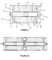
- a first embodiment variant is illustrated by means of Figures 2 and 2a in which there is shown two accumulator devices according to a first embodiment of the invention, interconnected.
- the accumulator device has a substantially cylindrical shape and comprises a storage element 10, enclosed in a confinement envelope 11. At both ends of the storage element 10 are arranged electrical collectors 12 and 13.
- Each collector is constituted by an electrically conductive part, with a flat face 14 welded to the storage element 10 and a convex face 15.
- a void space 16 is formed between the convex faces of two collectors placed end to end. This empty space contributes to the extraction of calories from the lateral faces.
- the male collector 12 may comprise a thread 17 which cooperates with a tapping 18 carried by one end of the female collector 13.
- the confinement envelope extends to the level of the collectors.
- the ends 20 and 21 may also be provided with latching means or even a thread, provided, however, that the chosen material is sufficiently flexible to allow a game when screwing the collectors.
- the seal may optionally be supplemented by the use of a seal or equivalent means.
- outlets 50 for the connection of external electronic modules may also be provided.
- the storage element is also traversed by a pipe 22, made of plastic or any non-electrically conductive material (or at least whose outer surface is not electrically conductive). To promote exchanges however, it is important that this tubular pipe does not constitute an excessive thermal barrier, so it will preferably relatively relatively, which also does not pose any problems because this pipe tube does not support mechanical stresses.
- the pipe 22 overflows the storage element and opens at the level of the convex faces 15.
- a non-conductive fluid such as for example air is used.
- a dielectric liquid could also be used.
- An equivalent to the accumulator devices of the figure 1 is the combination of carrier devices at both ends of male or female collectors, a train of collectors then being formed by associating "male” devices with “female” devices.
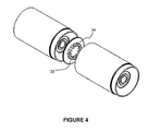
- the Figures 3 and 3A illustrate another embodiment of the invention, wherein the electrical connections are obtained by a plug / socket type system.
- the outer shell is formed of an electrical insulator, preferably a good thermal conductor.
- a storage element 10 surrounded by an insulating shell 11, with collectors 12 and 13, which, contrary to the variant illustrated above, are essentially identical, but may optionally have a surface state favoring heat exchange, which can be obtained for example by grooves 51.
- These grooves 51 thus constitute a means for guiding the flow of the thermal conditioning fluid. They can be created on the end faces or on the washer 40.
- Other means for guiding the flow of the thermal conditioning fluid can be envisaged, for example fins, preferably mounted on the bases of the heat sink element. storage.
- the central pipe passing through the storage element also serves as an electrical conductor and is constituted by two half-tubes 22 M and 22 F. These half-tubes are preferably made of a good thermal and electrical conductor material, which are fitted on one another by interposing a ring 23 formed of an electrically insulating material. The portion 24 of the half-tube 22M, and respectively the portion 25 of the half-tube 22F are electrically connected to the collectors 12 and 13 respectively. The function of the ring 23 is therefore to avoid a short circuit while allowing the use of 'a good material conductor to promote thermal and electrical exchanges with the storage element.
- half-tubes that meet about halfway along the storage element as in the illustrated case, but other arrangements can be made to avoid the short circuit, for example by replacing the half-tubes by a non-conductive composite material tube on which conductor poles could be fixed.
- the half-tubes are extended by ends 27 and 28 shaped to form one for a power supply plug (end 27) and the other a socket (end 28) in which a plug of another similar accumulator device can be introduced to connect two devices to each other.
- a plug is the positive pole of the device and the negative pole, but it goes without saying that the opposite is also possible.
- plugs and sockets can be threaded and tapped for a screw connection.
- the choice of complementary shapes formed for example by stamping is suitable.
- the shell 11 which also serves as confinement envelope can simply be fitted with or without complementary sealing means.
- the half-tubes comprises at least one lateral opening 29, 30 to allow the introduction of a cooling fluid on the side forming a plug as well as on the socket side when a plug is inserted in the plug, and thus allow to ensure the continuity of the flow of the thermal conditioning fluid when several accumulators are connected.
- Axial openings may possibly be envisaged.
- the shell 11 is extended at each of its ends by end caps 31 and 32 which extend beyond the storage element.
- end pieces are for example embossed, as in the case shown, for fitting by interlocking but it is also possible to provide other assembly methods such as for example a threading / tapping system to allow screwing the two accumulator devices l one to another. Sealing means may be provided to provide additional sealing at the end pieces.
- the accumulator device is thus adapted to forming trains of devices connected in series.
- a train having two devices has been realized.
- the end pieces make it possible to form a continuous sheath so that the cooling fluid follows through the train a path essentially represented by the arrows F, being introduced into the tube of the device on the left in the figure by an opening close to the plug, emerging at the other end by the opening near the socket to enter the intermediate chamber between two devices defined by the end caps and then entering the tube associated with the associated accumulator device.
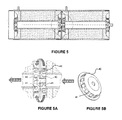
- FIG. 5A and 5B Another variant of the invention is shown schematically with the Figures 5, 5A and 5B .
- This variant can be interpreted as a hybrid variant of the previous two, with an electrical connection, the forcing system of the cooling fluid is provided by stamped cups 40, which have holes 41 to force the lateral passage of the cooling fluid.
- Accumulators according to the invention can easily form trains of four or more accumulators as illustrated in FIG. figure 6 , the end faces being used to connect the train to an electrical network, here materialized by electrical cables 44 and 45.
- the size of these connection elements may hinder the introduction of the refrigerant fluid, it is advantageous to provide end rings 46 and 47 to introduce the thermal conditioning fluid, these rings may also contain a system for forcing the flow of fluid, such as a fan, or the like to force the flow of refrigerant.
Landscapes
- Engineering & Computer Science (AREA)
- Power Engineering (AREA)
- General Chemical & Material Sciences (AREA)
- Manufacturing & Machinery (AREA)
- Chemical & Material Sciences (AREA)
- Chemical Kinetics & Catalysis (AREA)
- Electrochemistry (AREA)
- Transportation (AREA)
- Mechanical Engineering (AREA)
- Microelectronics & Electronic Packaging (AREA)
- Life Sciences & Earth Sciences (AREA)
- Sustainable Development (AREA)
- Sustainable Energy (AREA)
- Secondary Cells (AREA)
- Electric Double-Layer Capacitors Or The Like (AREA)
- Sealing Battery Cases Or Jackets (AREA)
- Supply And Distribution Of Alternating Current (AREA)
- Drilling And Exploitation, And Mining Machines And Methods (AREA)
- Vending Machines For Individual Products (AREA)
Claims (15)
- Speichervorrichtung, die ein elektrisches Speicherelement (10) aufweist, das von einer Durchgangsleitung (22) eines Kühlmittels durchquert wird, wobei ein erster (12) und ein zweiter (13) Sammler den positiven Pol und den negativen Pol der Speichervorrichtung bilden, dadurch gekennzeichnet, dass die Leitung (22) eine Länge hat, die größer ist als die des elektrischen Speicherelements und aus diesem an jedem seiner Enden vorsteht, und dass die Pole auf den gegenüberliegenden Seiten des elektrischen Speicherelements, durch die die Leitung mündet, liegen.
- Speichervorrichtung nach Anspruch 1, dadurch gekennzeichnet, dass die Leitung (22) an ihren zwei durchstoßenden Enden (22M, 22F) aus einem elektrischen Leiter besteht, wobei jedes Ende der Leitung mit einem Sammler verbunden ist und die zwei Enden elektrisch voneinander isoliert sind.
- Speichervorrichtung nach Anspruch 2, dadurch gekennzeichnet, dass eines der Enden der Leitung einen Stecker eines Netzteils (27) bildet, wobei das andere Ende eine Buchse (28) bildet, wobei das Ende, das eine Buchse (28) bildet und das Ende, das einen Stecker (27) bildet, ferner mit mindestens einer Öffnung (29, 30) versehen sind, um die Kontinuität des Fluidverlaufs zu gestatten, wenn zwei Speicher untereinander durch ihre entgegengesetzten Pole verbunden werden.
- Vorrichtung nach Anspruch 1, dadurch gekennzeichnet, dass die Sammler Außengewinde (17) oder Innengewinde (18) für das elektrische Verbinden von zwei Speichern tragen.
- Vorrichtung nach Anspruch 1, dadurch gekennzeichnet, dass sie eine Mutter (43) aufweist, die dazu bestimmt ist, mit einer Schraube (42) für das elektrische Verbinden von zwei Speichern untereinander zusammenzuwirken.
- Vorrichtung nach einem der vorhergehenden Ansprüche, dadurch gekennzeichnet, dass sie Mittel zum Führen des Fließens des Kühlmittels aufweist.
- Speichervorrichtung nach Anspruch 6, dadurch gekennzeichnet, dass die Führungsmittel von einer angebauten Unterlegscheibe (40) getragen werden.
- Speichervorrichtung nach einem der Ansprüche 1 bis 7, dadurch gekennzeichnet, dass sie Ansätze (31, 32) aufweist, die aus dem Speicherelement vorstehen.
- Speichervorrichtung nach Anspruch 8, dadurch gekennzeichnet, dass die Ansätze (31, 32) gestanzt werden, um unter Kraftanwendung eingeschachtelt zu werden.
- Speichervorrichtung nach Anspruch 8, dadurch gekennzeichnet, dass die Ansätze (31, 32) ein Außengewinde oder ein Innengewinde haben, um eine Schraubverbindung zu bilden.
- Speichervorrichtung nach einem der vorhergehenden Ansprüche, dadurch gekennzeichnet, dass das elektrische Speicherelement ein Superkondensator ist.
- Speichervorrichtung nach Anspruch 11, dadurch gekennzeichnet, dass der Superkondensator aus einer Wicklung auf sich selbst eines Bogens besteht, das zwei Blätter aufweist, die jeweils eine Anode und eine Kathode bilden, getrennt von einem Trenner, der mit Elektrolyt getränkt ist, wobei die Wicklung derart ausgeführt wird, dass der zentrale Teil des zylindrischen Elements im Wesentlichen leer ist und das Kühlrohr aufnehmen kann.
- Speichervorrichtung nach einem der Ansprüche 1 bis 12, dadurch gekennzeichnet, dass das elektrische Speicherelement eine Akkumulatorenbatterie ist.
- Zug, der aus mehreren Speichervorrichtungen nach einem der Ansprüche 1 bis 13 besteht, die in Serie verbunden sind.
- Zug nach Anspruch 14, dadurch gekennzeichnet, dass er Mittel (47) zum Verbinden des Zugs mit einer Quelle eines Kühlmittels aufweist.
Applications Claiming Priority (1)
| Application Number | Priority Date | Filing Date | Title |
|---|---|---|---|
| FR0851669A FR2928773A1 (fr) | 2008-03-14 | 2008-03-14 | Dispositif accumulateur d'energie electrique et train comportant une pluralite de tels dispositifs. |
Publications (2)
| Publication Number | Publication Date |
|---|---|
| EP2101336A1 EP2101336A1 (de) | 2009-09-16 |
| EP2101336B1 true EP2101336B1 (de) | 2011-01-12 |
Family
ID=39863008
Family Applications (1)
| Application Number | Title | Priority Date | Filing Date |
|---|---|---|---|
| EP20090154748 Active EP2101336B1 (de) | 2008-03-14 | 2009-03-10 | Vorrichtung zur Speicherung elektrischer Energie und eine Zusammenschaltung solcher Vorrichtungen |
Country Status (4)
| Country | Link |
|---|---|
| EP (1) | EP2101336B1 (de) |
| AT (1) | ATE495532T1 (de) |
| DE (1) | DE602009000548D1 (de) |
| FR (1) | FR2928773A1 (de) |
Families Citing this family (7)
| Publication number | Priority date | Publication date | Assignee | Title |
|---|---|---|---|---|
| DE102009053261A1 (de) | 2009-11-11 | 2011-05-12 | Jenoptik Automatisierungstechnik Gmbh | Vorrichtung zum Punktschweißen mit Laserstrahl |
| DE102010041538A1 (de) * | 2010-09-28 | 2012-03-29 | Siemens Aktiengesellschaft | Vorrichtung zur Energiespeicherung für ein elektrisches Triebfahrzeug |
| DE102012000996B4 (de) * | 2012-01-20 | 2022-01-27 | Sew-Eurodrive Gmbh & Co Kg | Anordnung mit einer Leiterplatte und Bauelementen |
| GB2532724B (en) * | 2014-11-24 | 2017-11-01 | Jaguar Land Rover Ltd | Rechargeable battery and cooling system therefor |
| FR3075477B1 (fr) * | 2017-12-14 | 2021-07-30 | Commissariat Energie Atomique | Traversee formant borne pour accumulateur electrochimique metal-ion, accumulateur associe |
| FR3076085B1 (fr) * | 2017-12-27 | 2022-03-04 | Accumulateurs Fixes | Couvercle d’element electrochimique a conduction thermique renforcee |
| DE102019106617A1 (de) * | 2019-03-15 | 2020-09-17 | Schaeffler Technologies AG & Co. KG | Elektrische Baueinheit mit elektrisch isoliertem Gehäuse; sowie Antriebsstrangeinheit |
Family Cites Families (4)
| Publication number | Priority date | Publication date | Assignee | Title |
|---|---|---|---|---|
| US3243672A (en) * | 1964-01-31 | 1966-03-29 | Sprague Electric Co | Fluid coolable capacitor |
| DE4105785A1 (de) * | 1991-02-23 | 1992-08-27 | Abb Patent Gmbh | Kuehlvorrichtung fuer einen kondensator |
| US6430024B1 (en) * | 2001-02-05 | 2002-08-06 | Thermal Corp. | Capacitor with heat pipe cooling |
| FR2863400B1 (fr) | 2003-12-03 | 2006-03-24 | Electricite De France | Systeme a supercondensateurs et procede d'assemblage d'un tel systeme |
-
2008
- 2008-03-14 FR FR0851669A patent/FR2928773A1/fr not_active Withdrawn
-
2009
- 2009-03-10 AT AT09154748T patent/ATE495532T1/de not_active IP Right Cessation
- 2009-03-10 DE DE200960000548 patent/DE602009000548D1/de active Active
- 2009-03-10 EP EP20090154748 patent/EP2101336B1/de active Active
Also Published As
| Publication number | Publication date |
|---|---|
| FR2928773A1 (fr) | 2009-09-18 |
| ATE495532T1 (de) | 2011-01-15 |
| DE602009000548D1 (de) | 2011-02-24 |
| EP2101336A1 (de) | 2009-09-16 |
Similar Documents
| Publication | Publication Date | Title |
|---|---|---|
| EP3360176B1 (de) | Verfahren zur herstellung eines moduls zur speicherung von elektrischer energie | |
| EP2101336A1 (de) | Vorrichtung zur Speicherung elektrischer Energie und eine Zusammenschaltung solcher Vorrichtungen | |
| US20230017407A1 (en) | Battery, battery module, battery pack and electric vehicle | |
| EP2630688B1 (de) | Batterie für einen elektromotor eines kraftfahrzeugs | |
| US10770693B2 (en) | Apparatus comprising battery cells and a method of assembling | |
| EP2599143A1 (de) | Batterie mit einfachem design und einfacher montage | |
| FR3007896A1 (fr) | Module de batterie pour vehicule electrique ou hybride integrant un echangeur de chaleur | |
| EP3314682B1 (de) | Elektrische energiespeichermodul | |
| EP3008772B1 (de) | Batteriepack für ein kraftfahrzeug | |
| WO2020165517A1 (fr) | Unité de batterie et véhicule automobile équipé d'au moins une telle unité | |
| EP2144775A2 (de) | Strombaugruppe für ein mikrohybrides system in einem automobil | |
| EP3809488A1 (de) | Dummy-batterie | |
| FR3062522A1 (fr) | Batterie refroidie et systeme comportant une telle batterie | |
| EP3667688B1 (de) | Elektrische einheit, die ein kapazitives element umfasst | |
| FR2973948A1 (fr) | Dispositif modulaire de cadre conducteur de puissance pour batterie de vehicule automobile, procede de montage de ce dispositif et batterie de vehicule automobile comprenant un tel dispositif | |
| EP2144322A2 (de) | Wiederaufladbares Akku-Set mit elektronischen Steuerschaltkreisen | |
| FR2863400A1 (fr) | Systeme a supercondensateurs et procede d'assemblage d'un tel systeme | |
| FR3104823A1 (fr) | Accumulateur électrochimique, notamment un accumulateur métal-ion, à emballage souple intégrant un ou plusieurs orifices de passage de fluide de refroidissement, module et procédé de fabrication associés. | |
| EP4602673B1 (de) | Kühlvorrichtung für eine pouchzelle einer elektrischen batterie | |
| FR3147431A1 (fr) | Module de batterie et procédé de fabrication associé | |
| FR3141810A1 (fr) | Ensemble pour batterie électrique | |
| FR3163497A1 (fr) | Bloc de batteries d’accumulateurs électriques. | |
| FR3141808A1 (fr) | Ensemble pour batterie électrique | |
| WO2024141293A1 (fr) | Module de batterie, notamment pour véhicule électrique et batterie comprenant un tel module ou une pluralité de tels modules | |
| WO2025088254A1 (fr) | Systeme de batterie de servitude |
Legal Events
| Date | Code | Title | Description |
|---|---|---|---|
| PUAI | Public reference made under article 153(3) epc to a published international application that has entered the european phase |
Free format text: ORIGINAL CODE: 0009012 |
|
| AK | Designated contracting states |
Kind code of ref document: A1 Designated state(s): AT BE BG CH CY CZ DE DK EE ES FI FR GB GR HR HU IE IS IT LI LT LU LV MC MK MT NL NO PL PT RO SE SI SK TR |
|
| AX | Request for extension of the european patent |
Extension state: AL BA RS |
|
| 17P | Request for examination filed |
Effective date: 20100208 |
|
| 17Q | First examination report despatched |
Effective date: 20100303 |
|
| AKX | Designation fees paid |
Designated state(s): AT BE BG CH CY CZ DE DK EE ES FI FR GB GR HR HU IE IS IT LI LT LU LV MC MK MT NL NO PL PT RO SE SI SK TR |
|
| GRAP | Despatch of communication of intention to grant a patent |
Free format text: ORIGINAL CODE: EPIDOSNIGR1 |
|
| GRAS | Grant fee paid |
Free format text: ORIGINAL CODE: EPIDOSNIGR3 |
|
| GRAA | (expected) grant |
Free format text: ORIGINAL CODE: 0009210 |
|
| AK | Designated contracting states |
Kind code of ref document: B1 Designated state(s): AT BE BG CH CY CZ DE DK EE ES FI FR GB GR HR HU IE IS IT LI LT LU LV MC MK MT NL NO PL PT RO SE SI SK TR |
|
| REG | Reference to a national code |
Ref country code: GB Ref legal event code: FG4D Free format text: NOT ENGLISH |
|
| REG | Reference to a national code |
Ref country code: CH Ref legal event code: EP |
|
| REG | Reference to a national code |
Ref country code: IE Ref legal event code: FG4D Free format text: LANGUAGE OF EP DOCUMENT: FRENCH |
|
| REF | Corresponds to: |
Ref document number: 602009000548 Country of ref document: DE Date of ref document: 20110224 Kind code of ref document: P |
|
| REG | Reference to a national code |
Ref country code: DE Ref legal event code: R096 Ref document number: 602009000548 Country of ref document: DE Effective date: 20110224 |
|
| REG | Reference to a national code |
Ref country code: NL Ref legal event code: VDEP Effective date: 20110112 |
|
| LTIE | Lt: invalidation of european patent or patent extension |
Effective date: 20110112 |
|
| PG25 | Lapsed in a contracting state [announced via postgrant information from national office to epo] |
Ref country code: LT Free format text: LAPSE BECAUSE OF FAILURE TO SUBMIT A TRANSLATION OF THE DESCRIPTION OR TO PAY THE FEE WITHIN THE PRESCRIBED TIME-LIMIT Effective date: 20110112 Ref country code: IS Free format text: LAPSE BECAUSE OF FAILURE TO SUBMIT A TRANSLATION OF THE DESCRIPTION OR TO PAY THE FEE WITHIN THE PRESCRIBED TIME-LIMIT Effective date: 20110512 Ref country code: SE Free format text: LAPSE BECAUSE OF FAILURE TO SUBMIT A TRANSLATION OF THE DESCRIPTION OR TO PAY THE FEE WITHIN THE PRESCRIBED TIME-LIMIT Effective date: 20110112 Ref country code: ES Free format text: LAPSE BECAUSE OF FAILURE TO SUBMIT A TRANSLATION OF THE DESCRIPTION OR TO PAY THE FEE WITHIN THE PRESCRIBED TIME-LIMIT Effective date: 20110423 Ref country code: LV Free format text: LAPSE BECAUSE OF FAILURE TO SUBMIT A TRANSLATION OF THE DESCRIPTION OR TO PAY THE FEE WITHIN THE PRESCRIBED TIME-LIMIT Effective date: 20110112 Ref country code: HR Free format text: LAPSE BECAUSE OF FAILURE TO SUBMIT A TRANSLATION OF THE DESCRIPTION OR TO PAY THE FEE WITHIN THE PRESCRIBED TIME-LIMIT Effective date: 20110112 Ref country code: NO Free format text: LAPSE BECAUSE OF FAILURE TO SUBMIT A TRANSLATION OF THE DESCRIPTION OR TO PAY THE FEE WITHIN THE PRESCRIBED TIME-LIMIT Effective date: 20110412 Ref country code: GR Free format text: LAPSE BECAUSE OF FAILURE TO SUBMIT A TRANSLATION OF THE DESCRIPTION OR TO PAY THE FEE WITHIN THE PRESCRIBED TIME-LIMIT Effective date: 20110413 Ref country code: PT Free format text: LAPSE BECAUSE OF FAILURE TO SUBMIT A TRANSLATION OF THE DESCRIPTION OR TO PAY THE FEE WITHIN THE PRESCRIBED TIME-LIMIT Effective date: 20110512 |
|
| REG | Reference to a national code |
Ref country code: IE Ref legal event code: FD4D |
|
| REG | Reference to a national code |
Ref country code: GB Ref legal event code: 746 Effective date: 20110801 |
|
| PG25 | Lapsed in a contracting state [announced via postgrant information from national office to epo] |
Ref country code: NL Free format text: LAPSE BECAUSE OF FAILURE TO SUBMIT A TRANSLATION OF THE DESCRIPTION OR TO PAY THE FEE WITHIN THE PRESCRIBED TIME-LIMIT Effective date: 20110112 Ref country code: AT Free format text: LAPSE BECAUSE OF FAILURE TO SUBMIT A TRANSLATION OF THE DESCRIPTION OR TO PAY THE FEE WITHIN THE PRESCRIBED TIME-LIMIT Effective date: 20110112 Ref country code: SI Free format text: LAPSE BECAUSE OF FAILURE TO SUBMIT A TRANSLATION OF THE DESCRIPTION OR TO PAY THE FEE WITHIN THE PRESCRIBED TIME-LIMIT Effective date: 20110112 Ref country code: CY Free format text: LAPSE BECAUSE OF FAILURE TO SUBMIT A TRANSLATION OF THE DESCRIPTION OR TO PAY THE FEE WITHIN THE PRESCRIBED TIME-LIMIT Effective date: 20110112 Ref country code: FI Free format text: LAPSE BECAUSE OF FAILURE TO SUBMIT A TRANSLATION OF THE DESCRIPTION OR TO PAY THE FEE WITHIN THE PRESCRIBED TIME-LIMIT Effective date: 20110112 Ref country code: PL Free format text: LAPSE BECAUSE OF FAILURE TO SUBMIT A TRANSLATION OF THE DESCRIPTION OR TO PAY THE FEE WITHIN THE PRESCRIBED TIME-LIMIT Effective date: 20110112 Ref country code: BG Free format text: LAPSE BECAUSE OF FAILURE TO SUBMIT A TRANSLATION OF THE DESCRIPTION OR TO PAY THE FEE WITHIN THE PRESCRIBED TIME-LIMIT Effective date: 20110412 |
|
| BERE | Be: lapsed |
Owner name: PEUGEOT CITROEN AUTOMOBILES S.A. Effective date: 20110331 |
|
| PG25 | Lapsed in a contracting state [announced via postgrant information from national office to epo] |
Ref country code: IE Free format text: LAPSE BECAUSE OF FAILURE TO SUBMIT A TRANSLATION OF THE DESCRIPTION OR TO PAY THE FEE WITHIN THE PRESCRIBED TIME-LIMIT Effective date: 20110112 Ref country code: MC Free format text: LAPSE BECAUSE OF NON-PAYMENT OF DUE FEES Effective date: 20110331 Ref country code: DK Free format text: LAPSE BECAUSE OF FAILURE TO SUBMIT A TRANSLATION OF THE DESCRIPTION OR TO PAY THE FEE WITHIN THE PRESCRIBED TIME-LIMIT Effective date: 20110112 Ref country code: EE Free format text: LAPSE BECAUSE OF FAILURE TO SUBMIT A TRANSLATION OF THE DESCRIPTION OR TO PAY THE FEE WITHIN THE PRESCRIBED TIME-LIMIT Effective date: 20110112 |
|
| REG | Reference to a national code |
Ref country code: DE Ref legal event code: R084 Ref document number: 602009000548 Country of ref document: DE Effective date: 20110725 |
|
| PLBE | No opposition filed within time limit |
Free format text: ORIGINAL CODE: 0009261 |
|
| STAA | Information on the status of an ep patent application or granted ep patent |
Free format text: STATUS: NO OPPOSITION FILED WITHIN TIME LIMIT |
|
| PG25 | Lapsed in a contracting state [announced via postgrant information from national office to epo] |
Ref country code: RO Free format text: LAPSE BECAUSE OF FAILURE TO SUBMIT A TRANSLATION OF THE DESCRIPTION OR TO PAY THE FEE WITHIN THE PRESCRIBED TIME-LIMIT Effective date: 20110112 Ref country code: SK Free format text: LAPSE BECAUSE OF FAILURE TO SUBMIT A TRANSLATION OF THE DESCRIPTION OR TO PAY THE FEE WITHIN THE PRESCRIBED TIME-LIMIT Effective date: 20110112 Ref country code: CZ Free format text: LAPSE BECAUSE OF FAILURE TO SUBMIT A TRANSLATION OF THE DESCRIPTION OR TO PAY THE FEE WITHIN THE PRESCRIBED TIME-LIMIT Effective date: 20110112 |
|
| 26N | No opposition filed |
Effective date: 20111013 |
|
| PG25 | Lapsed in a contracting state [announced via postgrant information from national office to epo] |
Ref country code: MT Free format text: LAPSE BECAUSE OF FAILURE TO SUBMIT A TRANSLATION OF THE DESCRIPTION OR TO PAY THE FEE WITHIN THE PRESCRIBED TIME-LIMIT Effective date: 20110112 Ref country code: IT Free format text: LAPSE BECAUSE OF FAILURE TO SUBMIT A TRANSLATION OF THE DESCRIPTION OR TO PAY THE FEE WITHIN THE PRESCRIBED TIME-LIMIT Effective date: 20110112 Ref country code: BE Free format text: LAPSE BECAUSE OF NON-PAYMENT OF DUE FEES Effective date: 20110331 |
|
| REG | Reference to a national code |
Ref country code: DE Ref legal event code: R097 Ref document number: 602009000548 Country of ref document: DE Effective date: 20111013 |
|
| PG25 | Lapsed in a contracting state [announced via postgrant information from national office to epo] |
Ref country code: MK Free format text: LAPSE BECAUSE OF FAILURE TO SUBMIT A TRANSLATION OF THE DESCRIPTION OR TO PAY THE FEE WITHIN THE PRESCRIBED TIME-LIMIT Effective date: 20110112 |
|
| PG25 | Lapsed in a contracting state [announced via postgrant information from national office to epo] |
Ref country code: LU Free format text: LAPSE BECAUSE OF NON-PAYMENT OF DUE FEES Effective date: 20110310 |
|
| PG25 | Lapsed in a contracting state [announced via postgrant information from national office to epo] |
Ref country code: TR Free format text: LAPSE BECAUSE OF FAILURE TO SUBMIT A TRANSLATION OF THE DESCRIPTION OR TO PAY THE FEE WITHIN THE PRESCRIBED TIME-LIMIT Effective date: 20110112 |
|
| PG25 | Lapsed in a contracting state [announced via postgrant information from national office to epo] |
Ref country code: HU Free format text: LAPSE BECAUSE OF FAILURE TO SUBMIT A TRANSLATION OF THE DESCRIPTION OR TO PAY THE FEE WITHIN THE PRESCRIBED TIME-LIMIT Effective date: 20110112 |
|
| REG | Reference to a national code |
Ref country code: CH Ref legal event code: PL |
|
| PG25 | Lapsed in a contracting state [announced via postgrant information from national office to epo] |
Ref country code: CH Free format text: LAPSE BECAUSE OF NON-PAYMENT OF DUE FEES Effective date: 20130331 Ref country code: LI Free format text: LAPSE BECAUSE OF NON-PAYMENT OF DUE FEES Effective date: 20130331 |
|
| PGFP | Annual fee paid to national office [announced via postgrant information from national office to epo] |
Ref country code: GB Payment date: 20140226 Year of fee payment: 6 |
|
| GBPC | Gb: european patent ceased through non-payment of renewal fee |
Effective date: 20150310 |
|
| PG25 | Lapsed in a contracting state [announced via postgrant information from national office to epo] |
Ref country code: GB Free format text: LAPSE BECAUSE OF NON-PAYMENT OF DUE FEES Effective date: 20150310 |
|
| REG | Reference to a national code |
Ref country code: FR Ref legal event code: PLFP Year of fee payment: 8 |
|
| REG | Reference to a national code |
Ref country code: FR Ref legal event code: PLFP Year of fee payment: 9 |
|
| REG | Reference to a national code |
Ref country code: FR Ref legal event code: PLFP Year of fee payment: 10 |
|
| REG | Reference to a national code |
Ref country code: FR Ref legal event code: CA Effective date: 20180312 Ref country code: FR Ref legal event code: CD Owner name: PEUGEOT CITROEN AUTOMOBILES SA, FR Effective date: 20180312 |
|
| PGFP | Annual fee paid to national office [announced via postgrant information from national office to epo] |
Ref country code: DE Payment date: 20260219 Year of fee payment: 18 |
|
| PGFP | Annual fee paid to national office [announced via postgrant information from national office to epo] |
Ref country code: FR Payment date: 20260219 Year of fee payment: 18 |