EP2101385A2 - Boîte de connexion au sol - Google Patents
Boîte de connexion au sol Download PDFInfo
- Publication number
- EP2101385A2 EP2101385A2 EP08021348A EP08021348A EP2101385A2 EP 2101385 A2 EP2101385 A2 EP 2101385A2 EP 08021348 A EP08021348 A EP 08021348A EP 08021348 A EP08021348 A EP 08021348A EP 2101385 A2 EP2101385 A2 EP 2101385A2
- Authority
- EP
- European Patent Office
- Prior art keywords
- handle
- cover
- lid
- web
- flap
- Prior art date
- Legal status (The legal status is an assumption and is not a legal conclusion. Google has not performed a legal analysis and makes no representation as to the accuracy of the status listed.)
- Granted
Links
Images



Classifications
-
- H—ELECTRICITY
- H02—GENERATION; CONVERSION OR DISTRIBUTION OF ELECTRIC POWER
- H02G—INSTALLATION OF ELECTRIC CABLES OR LINES, OR OF COMBINED OPTICAL AND ELECTRIC CABLES OR LINES
- H02G3/00—Installations of electric cables or lines or protective tubing therefor in or on buildings, equivalent structures or vehicles
- H02G3/02—Details
- H02G3/08—Distribution boxes; Connection or junction boxes
- H02G3/18—Distribution boxes; Connection or junction boxes providing line outlets
- H02G3/185—Floor outlets and access cups
Definitions
- the invention relates to a junction box with a can body, which has a top-side can body opening, and with a can body closing the can lid, wherein the can lid has an open to an edge of the can lid cable gland, wherein the can lid an upwardly facing and around the edges of the can lid and the cable passage opening encircling cover web, wherein in the cover web in the cable passage opening a cover flap is arranged, which between a closed position and an open position lying on the inside of the cable entry opening, parallel to the outer edge of the can lid extending and in lateral portions of the cover web, based on the cable feedthrough opening , mounted pivot axis is pivotable, wherein the top of the cover closes with an upper edge of the cover web, wherein the cover at least a n the sides, but not at the outer edge, has a downwardly facing flap web, wherein the cover flap is mounted on the pivot axis additionally outwardly displaceable, and wherein the outer ends of the flap web each having a recess, which on a cover
- junction boxes are, for example, in various variants from the literature DE 7511354 U .
- a handle is known from a completely different technological field, namely the motor vehicle door locks, whose outer surface is substantially flush with the outer door skin and is mounted about a spaced from a first end of the handle and extending parallel to the door outer skin pivot axis.
- the first end of the handle is pressed, the second end of the handle protrudes beyond the outer door skin and can then be pulled, ultimately actuating the motor vehicle door latch.
- the vehicle Mercedes 300 SL from the period around 1960.
- a junction box of the aforementioned construction is known.
- the problem arises that for maintenance or assembly or disassembly purposes, the can lid must be lifted out of the lid frame so that an operator gets access to the interior of the junction box. This is particularly difficult in the case of a closed cover flap, because there is no secure point of attack, because the can lid is completely closed and embedded in the lid frame.
- This problem is solved in the extent known from practice can lid in that a part of the cover web offset inwards and in the resulting space between cover web and lid frame a handle is arranged. This handle is pivotable about a horizontal handle pivot axis, wherein the handle pivot axis is spaced from a first end of the handle.
- an operator can operate the handle with the first end resting against the lid frame and lifting the can lid out of the lid frame.
- the problem with this embodiment is that in the normal position of the handle whose upper edge terminates with the upper edge of the cover web or the cover frame. An operator must first try in the area of the first end with a finger of a first hand to press down the handle slightly and then grab the outgoing second end of the handle with the second hand. This is cumbersome and also consuming in the production.
- the invention is therefore based on the technical problem of specifying a junction box, the can lid is easier to use and at the same time less expensive to manufacture.
- the invention teaches that between the inside of the cable gland opening extending cover web and the inside edge of the cover, a handle is disposed, wherein the handle in the region of a first end of the handle, but spaced from the first end of the handle, an orthogonal to the adjacent cover web extending and the Cover web and the handle cross-grip axis, wherein the top of the handle with the upper edge of the cover web and the top of the cover substantially closes, either the handle in the area between the handle pivot axis and the first end of the handle over the cover and the cover web has outstanding actuating projection, or the cover web and / or the cover flap next to the region between the handle pivot axis and the first end of the handle has an upwardly open Betrelifactsaus Principleung.
- the handle can be operated easily and only with one hand. While pressed with a finger of one hand on the handle in the region of the actuating projection or the actuating recess, the second end can be grasped with the thumb of the same hand and the can lid can be lifted therefrom out of the lid frame.
- production is easy, because no complex course of the cover web and / or a lid base must be established to allow a support of the handle against the lid frame. A support is rather not required, which is also associated with lower operating forces.
- the initiated by actuation of the handle lifting force runs approximately through the center of gravity of the can lid or in the essentially parallel to a can lid orthogonal and extending through the center of gravity of the can lid Axle is located, which when tilting the can lid this tilted not laterally and possibly tilted in the lid frame.
- the operation is so simplified and safer.
- the can lid in plan view will have a substantially square or rectangular shape. However, it is also possible to provide a round shape, in which case the cover web will be straight on the inside of the cable bushing opening.
- the can body is substantially box-shaped and closed at the bottom and sides.
- the handle in the region of a second end on a downwardly open actuating recess.
- This ensures that even a very flat actuating projection or a very flat Betsch Trentsaus Principleung sufficient to grasp the second end of the handle.
- the height of the actuating projection or the depth of the actuating recess in the range of 0.1 to 5 mm, preferably in the range of 0.5 to 2 mm, move.
- the distance between the actuating projection and the actuating recess of the handle pivot axis is advantageously in the range of 1 to 50 mm, preferably 5 to 20 mm.
- the distance of the handle pivot axis from the first end of the handle is preferably 5 to 50 mm, in particular 15 to 40 mm.
- the total length of the handle is suitably to allow one-handed operation, in the range of 50 to 250 mm, in particular from 100 to 200 mm.
- the top of the handle possibly with the exception of the actuating projection, the cover flap and the cover web, if necessary, with the exception of the Betreli Trentsaus principleung, form a flat and substantially closed surface with inwardly displaced and in the closed position cover. This ensures that a person walking over the junction box can not trip. Also in this respect, it is advantageous in the context of the invention that the actuating projection or the actuating recess can be very flat. To avoid pitfalls, it will also be useful in general, if the upper edge of the lid frame terminates with the upper edge of the lid web.
- connection between the handle, handle pivot axis and cover web can be arbitrary.
- it is a flying storage.
- the handle pivot axis may be rotationally fixed or rotatable.
- the handle pivot axis is formed by an axle element, preferably a screw, which freely rotatably passes through the lid web and is rotatably mounted in the handle.
- the lid frame and the can body may be formed as separable components, for example, characterized in that that the lid frame can be inserted into a Deckelrahmenaus supraung the can body.
- connection box In principle, all customary materials are suitable for a connection box according to the invention and its components. It is preferred if at least the lid frame and the can lid, with all its components, made of stainless steel is formed.
- the lid bottom extends at least partially into the cable feedthrough opening, namely to the extent that it supports the flap webs in the closed position of the cover flap and the handle in the rest position.
- the former is achieved by extending the lid bottom to at least a portion of the flap webs, preferably to below the entire flap webs.
- This also a particularly high load capacity of the cover is achieved in the closed position.
- the latter is achieved by extending the lid bottom in the cable feedthrough opening under at least a portion of the second end, preferably to below the second end of the handle as a whole.
- the lid bottom extends below the handle over its entire length, wherein the handle has at its lower side of the first end a chamfer which limits the angle of rotation of the handle from a rest position to an actuating position.
- the angle of rotation of the handle from the Rest position in the operating position can be established by appropriate training of the length of the first end of the handle (measured from the handle pivot axis) in conjunction with the height and the formation of the bevel between 10 ° and 80 °, preferably between 20 ° and 45 °. This also ensures that the handle after releasing always falls back to its rest position and can not stand up outstanding, which could form a trip hazard.
- junction boxes and associated can ends are generally well known to those skilled in the art and therefore need not to be shown. Therefore, only detailed views and functional views of a can lid used according to the invention are shown and explained below.
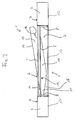
- the can lid 1 has an open to an edge of the can lid 1 cable feedthrough opening 2.
- the can lid 1 is formed by a lid bottom 17 and an upwardly facing and around the edges of the can bottom 17 and the cable bushing opening 2 encircling lid web 3.
- a cover 4 is arranged, which lies between a closed position and an open position lying on the inside of the cable feed opening 2, parallel to the outer edge of the can lid 1 extending and in lateral portions of the cover web 3, based on the cable passage opening 2, mounted pivot axis 5 is pivotable.
- the top 6 of the cover 4 closes in the closed position ( FIGS. 1 to 4 ) with an upper edge 7 of the cover web 3 from.
- the cover flap 4 has on the sides, but not on the outer edge, a downwardly facing flap web 8.
- the cover flap 4 is additionally slidably mounted on the pivot axis 5 to the outside, and the outer ends of the flap web 8 each have a latching recess 9, which latch on a cover frame of the can body with open and outwardly displaced cover 4.
- FIG. 5 the cover flap 4 has on the sides, but not on the outer edge, a downwardly facing flap web 8.
- the cover flap 4 is additionally slidably mounted on the pivot axis 5 to the outside, and the outer ends of the flap web 8 each have a latching recess 9, which latch on a cover frame of the can body with open and outwardly displaced cover 4.
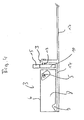
- a handle 10 is arranged, wherein the handle 10 in the region of a first end 11 of the handle 10, but spaced from the first end 11 of the handle 10, an orthogonal to adjacent cover web 3 extending and the cover web 3 and the handle 10 by cross handle pivot axis 12 has.
- the upper side 13 of the handle 10 closes in the rest position ( FIGS. 1 to 3 and 5 ) with the upper edge 7 of the cover web 3 and the top 6 of the cover 4 substantially.
- the handle 10 has an actuating projection 14 protruding beyond the cover flap 4 and the cover web 3.
- the cover web 3 and / or the cover 4 may have next to the region between the handle pivot axis 12 and the first end 11 of the handle 10 has an upwardly open actuating recess.
- FIGS. 1 to 5 A comparative consideration of the FIGS. 1 to 5 If one assumes that the lid bottom 17 extends at least partially into the cable feed-through opening 2, and to the extent that he the flap webs 8 in the closed position ( FIGS. 1 to 4 ) and the handle 10 in the rest position ( FIGS. 1 . 3 and 5 ). In this context, it is also advantageous if the lid bottom 17 extends below the handle 10 over its entire length, wherein the handle 10 at its lower side of the first end 11 has a chamfer 18 which limits the angle of rotation of the handle 10 from a rest position into the operating position. As a result, the lifting force is introduced into the lid bottom 17 and over-rotation of the handle 10 is prevented.
- the angle of rotation of the handle 10 from the rest position to the actuation position can be established by appropriate design of the length of the first end 11 of the handle 10 (measured from the handle pivot axis) in conjunction with its height and the formation of the chamfer 18.
- FIGS. 1 and 2 can be removed that the handle 10 in the region of a second end 15 has a downwardly open actuating recess 16, in which a finger can engage.
- FIG. 1 is removable, that with inwardly displaced and located in the closed position cover 3, the top of the handle 10, possibly with the exception of the actuating projection 14, the cover 3 and the cover web 3, optionally with the exception of Betreli Trentsaus Principleung, a flat and substantially closed Form surface.
- This is only interrupted by gaps exaggerated in the figures for the sake of clarity, which allow the movement of the various components relative to one another.
- FIGS. 3 to 5 can be seen that the Griffschwenkachse 12 is formed by an axis element, in the example a screw, which passes freely through the cover web 3 and is rotatably mounted in the handle 10.
Landscapes
- Engineering & Computer Science (AREA)
- Architecture (AREA)
- Civil Engineering (AREA)
- Structural Engineering (AREA)
- Closures For Containers (AREA)
- Connection Or Junction Boxes (AREA)
Priority Applications (1)
| Application Number | Priority Date | Filing Date | Title |
|---|---|---|---|
| PL08021348T PL2101385T3 (pl) | 2008-03-10 | 2008-12-09 | Podłogowa puszka połączeniowa |
Applications Claiming Priority (1)
| Application Number | Priority Date | Filing Date | Title |
|---|---|---|---|
| DE200820003432 DE202008003432U1 (de) | 2008-03-10 | 2008-03-10 | Anschlussbodendose |
Publications (3)
| Publication Number | Publication Date |
|---|---|
| EP2101385A2 true EP2101385A2 (fr) | 2009-09-16 |
| EP2101385A3 EP2101385A3 (fr) | 2016-02-24 |
| EP2101385B1 EP2101385B1 (fr) | 2017-10-18 |
Family
ID=39363747
Family Applications (1)
| Application Number | Title | Priority Date | Filing Date |
|---|---|---|---|
| EP08021348.1A Active EP2101385B1 (fr) | 2008-03-10 | 2008-12-09 | Boîte de connexion au sol |
Country Status (3)
| Country | Link |
|---|---|
| EP (1) | EP2101385B1 (fr) |
| DE (1) | DE202008003432U1 (fr) |
| PL (1) | PL2101385T3 (fr) |
Cited By (2)
| Publication number | Priority date | Publication date | Assignee | Title |
|---|---|---|---|---|
| EP3840155A1 (fr) | 2019-12-16 | 2021-06-23 | PUK Group GmbH & Co. KG | Boîte d'encastrement au sol pour les connexions électriques |
| GB2574175B (en) * | 2017-12-27 | 2022-06-15 | Cableduct Ltd | Outlet box and lid |
Citations (6)
| Publication number | Priority date | Publication date | Assignee | Title |
|---|---|---|---|---|
| DE7511354U (de) | 1975-04-11 | 1975-07-31 | Ackermann A | SchnurauslaB für Unterflurgerätedosen |
| DE2528951A1 (de) | 1975-06-28 | 1976-12-30 | Guenter W Stahl Kg | Verschlussdeckel fuer den dosenkasten einer unterflurgeraetedose |
| DE2037268C3 (de) | 1970-07-28 | 1980-01-17 | Fa. Albert Ackermann, 5270 Gummersbach | Gerätedose für elektrische Installationsgeräte zum Einbau in Stahlzellendecken |
| WO1998034310A1 (fr) | 1997-02-04 | 1998-08-06 | Albert Ackermann Gmbh + Co. Kg | Sortie de cable pour connecteur d'appareil encastre |
| DE20314597U1 (de) | 2003-05-07 | 2003-12-18 | Patz, Hermann | Versenkbare Abdeckung für einen Kabelauslass |
| DE102005006144A1 (de) | 2004-02-12 | 2005-09-01 | Thorsman & Co. Ab | Anschlussbodendose mit Kabelauslass |
Family Cites Families (3)
| Publication number | Priority date | Publication date | Assignee | Title |
|---|---|---|---|---|
| DE9402761U1 (de) * | 1994-02-19 | 1995-06-14 | Hager Electro GmbH, 66131 Saarbrücken | Tür- bzw. Deckelgriff eines Schrankes oder Kastens der Elektroinstallation |
| US6610927B2 (en) * | 2001-03-15 | 2003-08-26 | Thomas & Betts International, Inc. | Water resistant electrical box |
| DE20209189U1 (de) * | 2002-06-13 | 2002-08-14 | OBO Bettermann GmbH & Co. KG, 58710 Menden | Unterfluranschlussdose |
-
2008
- 2008-03-10 DE DE200820003432 patent/DE202008003432U1/de not_active Expired - Lifetime
- 2008-12-09 EP EP08021348.1A patent/EP2101385B1/fr active Active
- 2008-12-09 PL PL08021348T patent/PL2101385T3/pl unknown
Patent Citations (6)
| Publication number | Priority date | Publication date | Assignee | Title |
|---|---|---|---|---|
| DE2037268C3 (de) | 1970-07-28 | 1980-01-17 | Fa. Albert Ackermann, 5270 Gummersbach | Gerätedose für elektrische Installationsgeräte zum Einbau in Stahlzellendecken |
| DE7511354U (de) | 1975-04-11 | 1975-07-31 | Ackermann A | SchnurauslaB für Unterflurgerätedosen |
| DE2528951A1 (de) | 1975-06-28 | 1976-12-30 | Guenter W Stahl Kg | Verschlussdeckel fuer den dosenkasten einer unterflurgeraetedose |
| WO1998034310A1 (fr) | 1997-02-04 | 1998-08-06 | Albert Ackermann Gmbh + Co. Kg | Sortie de cable pour connecteur d'appareil encastre |
| DE20314597U1 (de) | 2003-05-07 | 2003-12-18 | Patz, Hermann | Versenkbare Abdeckung für einen Kabelauslass |
| DE102005006144A1 (de) | 2004-02-12 | 2005-09-01 | Thorsman & Co. Ab | Anschlussbodendose mit Kabelauslass |
Cited By (2)
| Publication number | Priority date | Publication date | Assignee | Title |
|---|---|---|---|---|
| GB2574175B (en) * | 2017-12-27 | 2022-06-15 | Cableduct Ltd | Outlet box and lid |
| EP3840155A1 (fr) | 2019-12-16 | 2021-06-23 | PUK Group GmbH & Co. KG | Boîte d'encastrement au sol pour les connexions électriques |
Also Published As
| Publication number | Publication date |
|---|---|
| EP2101385B1 (fr) | 2017-10-18 |
| DE202008003432U1 (de) | 2008-05-08 |
| PL2101385T3 (pl) | 2018-05-30 |
| EP2101385A3 (fr) | 2016-02-24 |
Similar Documents
| Publication | Publication Date | Title |
|---|---|---|
| DE202014103695U1 (de) | Stapelbarer Behälter | |
| DE102007038677A1 (de) | Abstreifeinrichtung, sowie Baumaschine | |
| EP2189381A1 (fr) | Récipient de transport ou de stockage portatif | |
| EP0422678B1 (fr) | Coffre à bagages | |
| DE202015009207U1 (de) | Ein zusammenbaubarer und zerlegbarer Behälter | |
| DE19652577A1 (de) | Verschlußvorrichtung für eine Wandöffnung | |
| EP2101385B1 (fr) | Boîte de connexion au sol | |
| EP1561405A1 (fr) | Couvercle de recipient et pot | |
| EP0668415A1 (fr) | Dispositif d'inspection pour les murs de bâtiment en particulier pour murs ignifuges | |
| DE102012111095B4 (de) | Schwenkhebelverschluss mit geringer Einbautiefe | |
| DE10257673A1 (de) | Verschlussvorrichtung einer in der Karosserie eines Fahrzeuges vorgesehenen Öffnung, und entsprechendes Fahrzeug | |
| AT12151U1 (de) | Führung für glasschiebetüre | |
| DE102014111337A1 (de) | Stapelbarer Behälter | |
| DE202008004791U1 (de) | Anschlussbodendose | |
| DE69311351T2 (de) | Verriegelungsvorrichtung für lösbare teile | |
| CH702820B1 (de) | Aushängbares Gelenk sowie Schachtabdeckung mit mindestens einem solchen Gelenk. | |
| EP3997004A1 (fr) | Récipient avec couvercle verrouillable | |
| EP2546159B1 (fr) | Récipient refermable | |
| EP2302751A1 (fr) | Unité de connexion destinée à l'utilisation dans un évidement dans une plaque | |
| DE10046409C2 (de) | Mülltonnengehäuse mit geführtem Haubendeckel | |
| DE3705202C1 (en) | Container | |
| EP2820729A2 (fr) | Porte d'armoire de commande | |
| EP3825504A1 (fr) | Dispositif de fermeture d'une ouverture d'espace | |
| DE202011004569U1 (de) | Kranbare Klappbehälter | |
| DE202016003861U1 (de) | Behälter zur Aufnahme von Gegenständen |
Legal Events
| Date | Code | Title | Description |
|---|---|---|---|
| PUAI | Public reference made under article 153(3) epc to a published international application that has entered the european phase |
Free format text: ORIGINAL CODE: 0009012 |
|
| AK | Designated contracting states |
Kind code of ref document: A2 Designated state(s): AT BE BG CH CY CZ DE DK EE ES FI FR GB GR HR HU IE IS IT LI LT LU LV MC MT NL NO PL PT RO SE SI SK TR |
|
| AX | Request for extension of the european patent |
Extension state: AL BA MK RS |
|
| PUAL | Search report despatched |
Free format text: ORIGINAL CODE: 0009013 |
|
| AK | Designated contracting states |
Kind code of ref document: A3 Designated state(s): AT BE BG CH CY CZ DE DK EE ES FI FR GB GR HR HU IE IS IT LI LT LU LV MC MT NL NO PL PT RO SE SI SK TR |
|
| AX | Request for extension of the european patent |
Extension state: AL BA MK RS |
|
| RIC1 | Information provided on ipc code assigned before grant |
Ipc: H02G 3/18 20060101ALI20160121BHEP Ipc: H02G 3/22 20060101AFI20160121BHEP |
|
| 17P | Request for examination filed |
Effective date: 20160307 |
|
| RBV | Designated contracting states (corrected) |
Designated state(s): AT BE BG CH CY CZ DE DK EE ES FI FR GB GR HR HU IE IS IT LI LT LU LV MC MT NL NO PL PT RO SE SI SK TR |
|
| AKX | Designation fees paid |
Designated state(s): AT BE BG CH CY CZ DE DK EE ES FI FR GB GR HR HU IE IS IT LI LT LU LV MC MT NL NO PL PT RO SE SI SK TR |
|
| AXX | Extension fees paid |
Extension state: MK Extension state: RS Extension state: BA Extension state: AL |
|
| GRAP | Despatch of communication of intention to grant a patent |
Free format text: ORIGINAL CODE: EPIDOSNIGR1 |
|
| STAA | Information on the status of an ep patent application or granted ep patent |
Free format text: STATUS: GRANT OF PATENT IS INTENDED |
|
| INTG | Intention to grant announced |
Effective date: 20170711 |
|
| GRAS | Grant fee paid |
Free format text: ORIGINAL CODE: EPIDOSNIGR3 |
|
| GRAA | (expected) grant |
Free format text: ORIGINAL CODE: 0009210 |
|
| STAA | Information on the status of an ep patent application or granted ep patent |
Free format text: STATUS: THE PATENT HAS BEEN GRANTED |
|
| AK | Designated contracting states |
Kind code of ref document: B1 Designated state(s): AT BE BG CH CY CZ DE DK EE ES FI FR GB GR HR HU IE IS IT LI LT LU LV MC MT NL NO PL PT RO SE SI SK TR |
|
| REG | Reference to a national code |
Ref country code: GB Ref legal event code: FG4D Free format text: NOT ENGLISH |
|
| REG | Reference to a national code |
Ref country code: CH Ref legal event code: EP |
|
| REG | Reference to a national code |
Ref country code: CH Ref legal event code: NV Representative=s name: BOVARD AG PATENT- UND MARKENANWAELTE, CH Ref country code: AT Ref legal event code: REF Ref document number: 938728 Country of ref document: AT Kind code of ref document: T Effective date: 20171115 Ref country code: IE Ref legal event code: FG4D Free format text: LANGUAGE OF EP DOCUMENT: GERMAN |
|
| REG | Reference to a national code |
Ref country code: DE Ref legal event code: R096 Ref document number: 502008015675 Country of ref document: DE |
|
| REG | Reference to a national code |
Ref country code: SE Ref legal event code: TRGR |
|
| REG | Reference to a national code |
Ref country code: NL Ref legal event code: FP |
|
| REG | Reference to a national code |
Ref country code: LT Ref legal event code: MG4D |
|
| PG25 | Lapsed in a contracting state [announced via postgrant information from national office to epo] |
Ref country code: NO Free format text: LAPSE BECAUSE OF FAILURE TO SUBMIT A TRANSLATION OF THE DESCRIPTION OR TO PAY THE FEE WITHIN THE PRESCRIBED TIME-LIMIT Effective date: 20180118 Ref country code: ES Free format text: LAPSE BECAUSE OF FAILURE TO SUBMIT A TRANSLATION OF THE DESCRIPTION OR TO PAY THE FEE WITHIN THE PRESCRIBED TIME-LIMIT Effective date: 20171018 Ref country code: LT Free format text: LAPSE BECAUSE OF FAILURE TO SUBMIT A TRANSLATION OF THE DESCRIPTION OR TO PAY THE FEE WITHIN THE PRESCRIBED TIME-LIMIT Effective date: 20171018 Ref country code: FI Free format text: LAPSE BECAUSE OF FAILURE TO SUBMIT A TRANSLATION OF THE DESCRIPTION OR TO PAY THE FEE WITHIN THE PRESCRIBED TIME-LIMIT Effective date: 20171018 |
|
| PG25 | Lapsed in a contracting state [announced via postgrant information from national office to epo] |
Ref country code: BG Free format text: LAPSE BECAUSE OF FAILURE TO SUBMIT A TRANSLATION OF THE DESCRIPTION OR TO PAY THE FEE WITHIN THE PRESCRIBED TIME-LIMIT Effective date: 20180118 Ref country code: HR Free format text: LAPSE BECAUSE OF FAILURE TO SUBMIT A TRANSLATION OF THE DESCRIPTION OR TO PAY THE FEE WITHIN THE PRESCRIBED TIME-LIMIT Effective date: 20171018 Ref country code: IS Free format text: LAPSE BECAUSE OF FAILURE TO SUBMIT A TRANSLATION OF THE DESCRIPTION OR TO PAY THE FEE WITHIN THE PRESCRIBED TIME-LIMIT Effective date: 20180218 Ref country code: GR Free format text: LAPSE BECAUSE OF FAILURE TO SUBMIT A TRANSLATION OF THE DESCRIPTION OR TO PAY THE FEE WITHIN THE PRESCRIBED TIME-LIMIT Effective date: 20180119 Ref country code: LV Free format text: LAPSE BECAUSE OF FAILURE TO SUBMIT A TRANSLATION OF THE DESCRIPTION OR TO PAY THE FEE WITHIN THE PRESCRIBED TIME-LIMIT Effective date: 20171018 |
|
| REG | Reference to a national code |
Ref country code: DE Ref legal event code: R097 Ref document number: 502008015675 Country of ref document: DE |
|
| PG25 | Lapsed in a contracting state [announced via postgrant information from national office to epo] |
Ref country code: SK Free format text: LAPSE BECAUSE OF FAILURE TO SUBMIT A TRANSLATION OF THE DESCRIPTION OR TO PAY THE FEE WITHIN THE PRESCRIBED TIME-LIMIT Effective date: 20171018 Ref country code: DK Free format text: LAPSE BECAUSE OF FAILURE TO SUBMIT A TRANSLATION OF THE DESCRIPTION OR TO PAY THE FEE WITHIN THE PRESCRIBED TIME-LIMIT Effective date: 20171018 Ref country code: EE Free format text: LAPSE BECAUSE OF FAILURE TO SUBMIT A TRANSLATION OF THE DESCRIPTION OR TO PAY THE FEE WITHIN THE PRESCRIBED TIME-LIMIT Effective date: 20171018 |
|
| PLBE | No opposition filed within time limit |
Free format text: ORIGINAL CODE: 0009261 |
|
| STAA | Information on the status of an ep patent application or granted ep patent |
Free format text: STATUS: NO OPPOSITION FILED WITHIN TIME LIMIT |
|
| PG25 | Lapsed in a contracting state [announced via postgrant information from national office to epo] |
Ref country code: RO Free format text: LAPSE BECAUSE OF FAILURE TO SUBMIT A TRANSLATION OF THE DESCRIPTION OR TO PAY THE FEE WITHIN THE PRESCRIBED TIME-LIMIT Effective date: 20171018 Ref country code: SE Free format text: LAPSE BECAUSE OF NON-PAYMENT OF DUE FEES Effective date: 20171210 Ref country code: IT Free format text: LAPSE BECAUSE OF FAILURE TO SUBMIT A TRANSLATION OF THE DESCRIPTION OR TO PAY THE FEE WITHIN THE PRESCRIBED TIME-LIMIT Effective date: 20171018 |
|
| REG | Reference to a national code |
Ref country code: IE Ref legal event code: MM4A |
|
| 26N | No opposition filed |
Effective date: 20180719 |
|
| GBPC | Gb: european patent ceased through non-payment of renewal fee |
Effective date: 20180118 |
|
| PG25 | Lapsed in a contracting state [announced via postgrant information from national office to epo] |
Ref country code: MT Free format text: LAPSE BECAUSE OF FAILURE TO SUBMIT A TRANSLATION OF THE DESCRIPTION OR TO PAY THE FEE WITHIN THE PRESCRIBED TIME-LIMIT Effective date: 20171018 Ref country code: LU Free format text: LAPSE BECAUSE OF NON-PAYMENT OF DUE FEES Effective date: 20171209 |
|
| REG | Reference to a national code |
Ref country code: FR Ref legal event code: ST Effective date: 20180831 |
|
| PG25 | Lapsed in a contracting state [announced via postgrant information from national office to epo] |
Ref country code: IE Free format text: LAPSE BECAUSE OF NON-PAYMENT OF DUE FEES Effective date: 20171209 Ref country code: FR Free format text: LAPSE BECAUSE OF NON-PAYMENT OF DUE FEES Effective date: 20180102 |
|
| PG25 | Lapsed in a contracting state [announced via postgrant information from national office to epo] |
Ref country code: GB Free format text: LAPSE BECAUSE OF NON-PAYMENT OF DUE FEES Effective date: 20180118 Ref country code: SI Free format text: LAPSE BECAUSE OF FAILURE TO SUBMIT A TRANSLATION OF THE DESCRIPTION OR TO PAY THE FEE WITHIN THE PRESCRIBED TIME-LIMIT Effective date: 20171018 |
|
| PGFP | Annual fee paid to national office [announced via postgrant information from national office to epo] |
Ref country code: CZ Payment date: 20181231 Year of fee payment: 11 |
|
| PG25 | Lapsed in a contracting state [announced via postgrant information from national office to epo] |
Ref country code: MC Free format text: LAPSE BECAUSE OF FAILURE TO SUBMIT A TRANSLATION OF THE DESCRIPTION OR TO PAY THE FEE WITHIN THE PRESCRIBED TIME-LIMIT Effective date: 20171018 Ref country code: HU Free format text: LAPSE BECAUSE OF FAILURE TO SUBMIT A TRANSLATION OF THE DESCRIPTION OR TO PAY THE FEE WITHIN THE PRESCRIBED TIME-LIMIT; INVALID AB INITIO Effective date: 20081209 |
|
| PG25 | Lapsed in a contracting state [announced via postgrant information from national office to epo] |
Ref country code: CY Free format text: LAPSE BECAUSE OF NON-PAYMENT OF DUE FEES Effective date: 20171018 |
|
| PG25 | Lapsed in a contracting state [announced via postgrant information from national office to epo] |
Ref country code: TR Free format text: LAPSE BECAUSE OF FAILURE TO SUBMIT A TRANSLATION OF THE DESCRIPTION OR TO PAY THE FEE WITHIN THE PRESCRIBED TIME-LIMIT Effective date: 20171018 |
|
| PG25 | Lapsed in a contracting state [announced via postgrant information from national office to epo] |
Ref country code: PT Free format text: LAPSE BECAUSE OF FAILURE TO SUBMIT A TRANSLATION OF THE DESCRIPTION OR TO PAY THE FEE WITHIN THE PRESCRIBED TIME-LIMIT Effective date: 20171018 |
|
| PG25 | Lapsed in a contracting state [announced via postgrant information from national office to epo] |
Ref country code: CZ Free format text: LAPSE BECAUSE OF NON-PAYMENT OF DUE FEES Effective date: 20191209 |
|
| PGFP | Annual fee paid to national office [announced via postgrant information from national office to epo] |
Ref country code: PL Payment date: 20211108 Year of fee payment: 14 |
|
| PGFP | Annual fee paid to national office [announced via postgrant information from national office to epo] |
Ref country code: NL Payment date: 20231228 Year of fee payment: 16 Ref country code: AT Payment date: 20231227 Year of fee payment: 16 |
|
| PGFP | Annual fee paid to national office [announced via postgrant information from national office to epo] |
Ref country code: BE Payment date: 20231228 Year of fee payment: 16 |
|
| REG | Reference to a national code |
Ref country code: DE Ref legal event code: R082 Ref document number: 502008015675 Country of ref document: DE Representative=s name: GULDE & PARTNER PATENT- UND RECHTSANWALTSKANZL, DE |
|
| PGFP | Annual fee paid to national office [announced via postgrant information from national office to epo] |
Ref country code: DE Payment date: 20231219 Year of fee payment: 16 Ref country code: CH Payment date: 20240102 Year of fee payment: 16 |
|
| PG25 | Lapsed in a contracting state [announced via postgrant information from national office to epo] |
Ref country code: PL Free format text: LAPSE BECAUSE OF NON-PAYMENT OF DUE FEES Effective date: 20221209 |
|
| REG | Reference to a national code |
Ref country code: DE Ref legal event code: R119 Ref document number: 502008015675 Country of ref document: DE |
|
| REG | Reference to a national code |
Ref country code: CH Ref legal event code: PL |
|
| REG | Reference to a national code |
Ref country code: NL Ref legal event code: MM Effective date: 20250101 |
|
| REG | Reference to a national code |
Ref country code: AT Ref legal event code: MM01 Ref document number: 938728 Country of ref document: AT Kind code of ref document: T Effective date: 20241209 |
|
| PG25 | Lapsed in a contracting state [announced via postgrant information from national office to epo] |
Ref country code: NL Free format text: LAPSE BECAUSE OF NON-PAYMENT OF DUE FEES Effective date: 20250101 |
|
| REG | Reference to a national code |
Ref country code: BE Ref legal event code: MM Effective date: 20241231 |
|
| PG25 | Lapsed in a contracting state [announced via postgrant information from national office to epo] |
Ref country code: DE Free format text: LAPSE BECAUSE OF NON-PAYMENT OF DUE FEES Effective date: 20250701 |
|
| PG25 | Lapsed in a contracting state [announced via postgrant information from national office to epo] |
Ref country code: BE Free format text: LAPSE BECAUSE OF NON-PAYMENT OF DUE FEES Effective date: 20241231 |
|
| PG25 | Lapsed in a contracting state [announced via postgrant information from national office to epo] |
Ref country code: AT Free format text: LAPSE BECAUSE OF NON-PAYMENT OF DUE FEES Effective date: 20241209 |
|
| PG25 | Lapsed in a contracting state [announced via postgrant information from national office to epo] |
Ref country code: CH Free format text: LAPSE BECAUSE OF NON-PAYMENT OF DUE FEES Effective date: 20241231 |