EP2101426B1 - Procédé de contrôle d'amplificateur optique à fibre dopée à l'erbium (EDFA) et agencement d'amplificateur - Google Patents
Procédé de contrôle d'amplificateur optique à fibre dopée à l'erbium (EDFA) et agencement d'amplificateur Download PDFInfo
- Publication number
- EP2101426B1 EP2101426B1 EP08004729A EP08004729A EP2101426B1 EP 2101426 B1 EP2101426 B1 EP 2101426B1 EP 08004729 A EP08004729 A EP 08004729A EP 08004729 A EP08004729 A EP 08004729A EP 2101426 B1 EP2101426 B1 EP 2101426B1
- Authority
- EP
- European Patent Office
- Prior art keywords
- pump
- power
- amplifier
- signal
- primary
- Prior art date
- Legal status (The legal status is an assumption and is not a legal conclusion. Google has not performed a legal analysis and makes no representation as to the accuracy of the status listed.)
- Active
Links
Images



Classifications
-
- H—ELECTRICITY
- H04—ELECTRIC COMMUNICATION TECHNIQUE
- H04B—TRANSMISSION
- H04B10/00—Transmission systems employing electromagnetic waves other than radio-waves, e.g. infrared, visible or ultraviolet light, or employing corpuscular radiation, e.g. quantum communication
- H04B10/29—Repeaters
- H04B10/291—Repeaters in which processing or amplification is carried out without conversion of the main signal from optical form
- H04B10/293—Signal power control
- H04B10/2931—Signal power control using AGC
-
- H—ELECTRICITY
- H01—ELECTRIC ELEMENTS
- H01S—DEVICES USING THE PROCESS OF LIGHT AMPLIFICATION BY STIMULATED EMISSION OF RADIATION [LASER] TO AMPLIFY OR GENERATE LIGHT; DEVICES USING STIMULATED EMISSION OF ELECTROMAGNETIC RADIATION IN WAVE RANGES OTHER THAN OPTICAL
- H01S3/00—Lasers, i.e. devices using stimulated emission of electromagnetic radiation in the infrared, visible or ultraviolet wave range
- H01S3/05—Construction or shape of optical resonators; Accommodation of active medium therein; Shape of active medium
- H01S3/06—Construction or shape of active medium
- H01S3/063—Waveguide lasers, i.e. whereby the dimensions of the waveguide are of the order of the light wavelength
- H01S3/067—Fibre lasers
- H01S3/06754—Fibre amplifiers
- H01S3/06758—Tandem amplifiers
-
- H—ELECTRICITY
- H01—ELECTRIC ELEMENTS
- H01S—DEVICES USING THE PROCESS OF LIGHT AMPLIFICATION BY STIMULATED EMISSION OF RADIATION [LASER] TO AMPLIFY OR GENERATE LIGHT; DEVICES USING STIMULATED EMISSION OF ELECTROMAGNETIC RADIATION IN WAVE RANGES OTHER THAN OPTICAL
- H01S3/00—Lasers, i.e. devices using stimulated emission of electromagnetic radiation in the infrared, visible or ultraviolet wave range
- H01S3/10—Controlling the intensity, frequency, phase, polarisation or direction of the emitted radiation, e.g. switching, gating, modulating or demodulating
- H01S3/13—Stabilisation of laser output parameters, e.g. frequency or amplitude
- H01S3/1301—Stabilisation of laser output parameters, e.g. frequency or amplitude in optical amplifiers
- H01S3/13013—Stabilisation of laser output parameters, e.g. frequency or amplitude in optical amplifiers by controlling the optical pumping
-
- H—ELECTRICITY
- H01—ELECTRIC ELEMENTS
- H01S—DEVICES USING THE PROCESS OF LIGHT AMPLIFICATION BY STIMULATED EMISSION OF RADIATION [LASER] TO AMPLIFY OR GENERATE LIGHT; DEVICES USING STIMULATED EMISSION OF ELECTROMAGNETIC RADIATION IN WAVE RANGES OTHER THAN OPTICAL
- H01S2301/00—Functional characteristics
- H01S2301/02—ASE (amplified spontaneous emission), noise; Reduction thereof
-
- H—ELECTRICITY
- H01—ELECTRIC ELEMENTS
- H01S—DEVICES USING THE PROCESS OF LIGHT AMPLIFICATION BY STIMULATED EMISSION OF RADIATION [LASER] TO AMPLIFY OR GENERATE LIGHT; DEVICES USING STIMULATED EMISSION OF ELECTROMAGNETIC RADIATION IN WAVE RANGES OTHER THAN OPTICAL
- H01S3/00—Lasers, i.e. devices using stimulated emission of electromagnetic radiation in the infrared, visible or ultraviolet wave range
- H01S3/09—Processes or apparatus for excitation, e.g. pumping
- H01S3/091—Processes or apparatus for excitation, e.g. pumping using optical pumping
- H01S3/094—Processes or apparatus for excitation, e.g. pumping using optical pumping by coherent light
- H01S3/094061—Shared pump, i.e. pump light of a single pump source is used to pump plural gain media in parallel
-
- H—ELECTRICITY
- H01—ELECTRIC ELEMENTS
- H01S—DEVICES USING THE PROCESS OF LIGHT AMPLIFICATION BY STIMULATED EMISSION OF RADIATION [LASER] TO AMPLIFY OR GENERATE LIGHT; DEVICES USING STIMULATED EMISSION OF ELECTROMAGNETIC RADIATION IN WAVE RANGES OTHER THAN OPTICAL
- H01S3/00—Lasers, i.e. devices using stimulated emission of electromagnetic radiation in the infrared, visible or ultraviolet wave range
- H01S3/10—Controlling the intensity, frequency, phase, polarisation or direction of the emitted radiation, e.g. switching, gating, modulating or demodulating
- H01S3/10007—Controlling the intensity, frequency, phase, polarisation or direction of the emitted radiation, e.g. switching, gating, modulating or demodulating in optical amplifiers
- H01S3/10015—Controlling the intensity, frequency, phase, polarisation or direction of the emitted radiation, e.g. switching, gating, modulating or demodulating in optical amplifiers by monitoring or controlling, e.g. attenuating, the input signal
-
- H—ELECTRICITY
- H01—ELECTRIC ELEMENTS
- H01S—DEVICES USING THE PROCESS OF LIGHT AMPLIFICATION BY STIMULATED EMISSION OF RADIATION [LASER] TO AMPLIFY OR GENERATE LIGHT; DEVICES USING STIMULATED EMISSION OF ELECTROMAGNETIC RADIATION IN WAVE RANGES OTHER THAN OPTICAL
- H01S3/00—Lasers, i.e. devices using stimulated emission of electromagnetic radiation in the infrared, visible or ultraviolet wave range
- H01S3/10—Controlling the intensity, frequency, phase, polarisation or direction of the emitted radiation, e.g. switching, gating, modulating or demodulating
- H01S3/13—Stabilisation of laser output parameters, e.g. frequency or amplitude
- H01S3/1305—Feedback control systems
Definitions
- the invention refers to a Method for controlling an erbium doped fibre amplifier and an amplifier arrangement.
- Erbium Doped Fibre Amplifiers are widely deployed in optical D ense W avelength D ivision M ultiplexing (DWDM) transmission systems due to their capability to amplify all DWDM signal simultaneously in an almost satisfying manner. Furthermore, EDFAs represent key components for the integration of point-to-point links in optical networks. This trend results in an increased number of amplifiers used in an optical network due to the additional losses introduced by switches, multiplexers etc. Furthermore, optical networking technology has become attractive for regional and metropolitan networks with stringent cost requirements.
- the core of the amplifier is given by the gain medium, i.e. the "Erbium Doped Fibre", that provides the amplification, and by the laser pumps, that provide the power to allow that a sufficient part of the dopant ions in the Erbium Doped Fibre (EDF) leave the ground state to reach the desired excited state level.
- the gain medium i.e. the "Erbium Doped Fibre”
- the laser pumps that provide the power to allow that a sufficient part of the dopant ions in the Erbium Doped Fibre (EDF) leave the ground state to reach the desired excited state level.
- Practical implementations of EDFAs deploy additional passive components such as tap couplers/splitters, signal monitors, WDM couplers to couple the pump radiation and the signal light into the EDF, isolators, etc, too.
- pump lasers represent the driving element. As a consequence, the number of pumps must be kept as low as possible to significantly reduce EDFA costs.
- the noise figure of setups based on pump slitting that are operated at constant gain is significantly larger at small input power, i.e. small channel count.
- the maximum number of spans is limited by the noise performance at small channel count.
- high values of the splitting ratio can be considered.
- lower values of the splitting ratio are required (i.e. high pump power in the second EDF coil).
- high values of the splitting ratio are related to lower output power levels, i.e. the maximum gain provided by the amplifier is reduced.
- the choice of a fixed splitting ratio is based on a trade-off between these two constraints.
- Splitting factors between 1 and 0 have been considered. It is shown for a pump power splitting setup that an optimized low noise figure for low input power is obtained in a two stage optical amplifier for a splitting ratio of 1. At higher input power levels the splitting factor is reduced for optimized noise performance. The output power increases monotonously when decreasing the splitting factor. Maximum output power is achieved if a major of the pump power is provided to the second amplifier fiber.
- Drake at al. disclose in the patent US 6 377 394 a gain controlled amplifier with three different pump sources which are controlled in dependence of the input and the output power according to a mapping device in order to maintain constant gain. This is an very expensive solution which is not acceptable in most applications.
- a way to improve the signal quality is achieved by a method according to claim 1.
- the insertion loss of the tuneable splitter as a bulk element is slightly higher than for the fixed splitter.
- the implementation of the proposed setup by means of discrete components will be affected by this drawback. However, this is avoided as soon as the proposed configuration is implemented as an entity with a Planar Lightwave Circuit (PLC) apis proach.
- PLC Planar Lightwave Circuit
- the tuneable splitter can be integrated on a chip without causing additional losses with respect to the architecture based on the fixed splitting ratio.
- the PLC approach is attractive because of the reduced mechanical dimensions and reduced manufacturing effort, and the proposed architecture will allow for building compact amplifiers with very good noise performances.
- the gain medium could be any kind of material or réelle providing light amplification (meaning that only the passive components are integrated on the chip), but a fully integrated approach based on Erbium Doped Waveguides (EDW) represents an alternative choice.
- EDW Erbium Doped Waveguides
- the advantage of the proposed approach is the fact that the pump power level and the splitting ratio can be set independently, so that at small channel count or at output power levels below the maximum the noise performances are improved by means of a high splitting ratio ⁇ (i.e. a large portion of the pump light coupled into the first EDF coil), whereas at high channel count the output power can be increased by setting a lower value for the splitting ratio.
- the presence of two degrees of freedom affects the control strategy. Since the splitting ratio of the tuneable element and the pump power level can be set independently, these quantities can be regarded as the actuating (control) variables for the proposed solution. As a consequence, the control strategy is different. Focusing the attention on the new setup, the control of the amplifier must act on the two variables properly to guarantee best performances. Generally, a certain output gain level can be achieved with different couples of pump power and splitting ratio. However, optimum performance is only obtained with a properly chosen combination of the two parameters.
- actuating (control) variables from two to one is desirable to speed-up the control, so that only one variable is to be adjusted as a function of the output power. This is achievable by defining the pump power entering the second EDF stage as the unique actuating variable.
- the control circuits uses a feed-forward part that causes a variation in the (pump power) actuating variable as a consequence of a variation in the input power.
- a common application of this approach is the operation at constant gain of EDFAs.
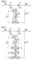
- FIG 1 shows an illustrative arrangement of an optical amplifier embodying the principles of the invention.
- the optical amplifier has two amplifier stages A1 and A2 comprising erbium doped fibres 4 and 6, labelled EDF1, EDF2.
- the first amplifier stage A1 contains a first coupler 3 for inserting a first pump signal S1 into the fibre4 and the second amplifier stage A2 contains a second coupler 5 for inserting a second pump signal S2 into the fibre6.
- An input signal S IN is received at an input 1 of the amplifier and passed through a first splitter 2, a first isolator I1, the first amplifier stage A1, a second isolator I2, the second amplifier stage A2, a third isolator I3, and a second coupler 7 before it is output as an amplified output signal S OUT at the output 13.
- the serial connection may also comprise filters, attenuators and other additional elements.
- the output power P OUT or the amplifier gain is controlled by a control unit 12 receiving monitoring signals representing input power P IN and output power P OUT from a first optical-electrical converter 8 and a second optical-electrical converter 9, which are connected to the first and second splitters 2 and 7 respectively.
- the control unit 12 outputs control signals pc and ⁇ c determining the total pump power P PUMP of the primary pump signal S PUMP and the splitting factor ⁇ ( FIG 4 , FIG 5 ).
- the splitter 10 is dividing the primary pump signal Pp UMP into the first and the second pump signal S1, S2 according to said splitting factor. The inventive control method will be explained later.
- FIG 2 shows a simplified block diagram of this amplifier arrangement. Monitoring of the input power is not required in most operational modes, e.g. for operation at constant output power.
- This simplified setup is used for the following explanation of the invention.
- the control unit compares the output power P OUT with an internal or external reference value P TAR (TAR - TARGET, FIG 7 ).
- FIG 3 shows more details of the control unit.
- the control unit 12 is split into three functional parts referred to as first control unit 121, second control unit 122 and third control unit 123.
- the output power P OUT is a function of the second pump power P2 ( FIG 5 ) launched into the second EDF coil 6.
- a single corresponding "primary actuating variable" p2 (control variable) is calculated by the first control unit 121, which has the function of a conventional controller and can be realized as analogue or digital circuit (CONTROL S2 indicates, that the first actuating variable p2 is derived to control the second pump signal S2).
- the second control unit 122 two secondary actuating variables: The splitting factor ⁇ and a corresponding variable p determining the total pump power P PUMP of the primary pump signal S PUMP .
- Both "secondary actuating variables" p and ⁇ ( ⁇ is used for the variable and for the splitting factor) determine the powers of the first and the second pump signal S1, S2 and are fed to the third control unit 123.
- the third control unit 123 converts the secondary actuating variables p, ⁇ into the physical control signals pc and ⁇ c.
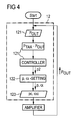
- a flow diagram shown in FIG 4 may illustrate how the control units work.
- the output power P OUT is measured (in another not shown embodiment the gain or/and the input power is measured).
- the fourth step is to optimize the splitting factor ⁇ - if not already done - and the total pump power.
- the secondary actuating (control) variables p, ⁇ are calculated determining the total pump power P PUMP ( FIG 5, FIG 6 ) and the splitting factor ⁇ .
- the next step is to convert these variables into physical control signals pc and ⁇ c adjusting the total pump power P PUMP of the pump light source 11 and the splitting factor ⁇ of the tuneable splitter 10. This control method is the key part of the invention.
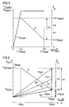
- a solid line in this diagram shows the relation between the second pump power P2 of the second pump signal S2 and the total pump power P PUMP . Both values are standardised.
- a dashed line shows the relation between the second pump power P2 and the variable splitting factor ⁇ .
- the power of the first pump signal P1, injected into the first amplifier stage AS1 can be calculated from the power of the total pump signal P PUMP or the second pump signal S2 and the splitting factor ⁇ .
- the splitting factor has to be reduced.
- the splitting factor can go down to a minimum value ⁇ MIN , in this example 0,2.
- the maximum total pump power remains constant - horizontal solid line - while the second pump power P2 is increased according (1 - ⁇ ).
- a maximum total pump power P PUMP should be chosen, which is lesser than the possible maximum total pump power. Then a fast pump power control could be combined with a slower splitting factor optimisation.
- FIG 6 shows the relation between the total pump power P PUMP respectively the splitting factor ⁇ and the output power P OUT of the amplifier.
- a dash-dotted line shows the relation between the output power P OUT and the splitting factor ⁇ marked on the x-axis.
- the vertical characteristic line f( ⁇ ) shows the output power P OUT as a function of the splitting factor ⁇ while the total pump power P PMAX remains constant.
- the splitting factor is additional marked on the vertical axis on the right side of the diagram.
- the output power P OUT is approximately proportional to the second pump power P2 of the second pump signal S2 and increases according to P PMAX (1 - ⁇ ) up to P OUTMAX , when the splitting factor reaches its minimum value ⁇ MIN and the second pump power P2 also reaches its maximum value P2 MAX .
- the solid lines are used for operating the amplifier.
- the dashed lines show only the relations for other fixed splitting parameters ⁇ 1 , ⁇ 2 , ⁇ MIN .
- FIG 7 shows the method steps in a more detailed way for normal operation. Beside this flow diagram other flow diagrams lead to the same result.
- the output power P OUT is measured in a first step after START or derived from other signals and in a second step compared with a reference value P TAR .
- the result ⁇ p is fed to a controller. In a basic configuration, it is added to a former actuating variable and results in a new actuating variable p2 determining the second pump power P2. Then it is checked if the total pump power equals the maximum total available pump power P PMAX . According to the result the pump signal or the splitting factor is adjusted.
- a more enhanced embodiment of the invention uses a superior method for calculating the actuating variable p2 and also calculated values to determine the secondary variables.
- a total pump power reference value p PMAX is compared with a calculated pump power value p2/(1- ⁇ MAX ) (corresponds to comparing P PMAX with P2/(1- ⁇ MAX ), which will be used in the following description).
- the splitting factor ⁇ is adjusted while the total pump power P PMAX remains at its maximum value. Only one pair of the secondary actuating variables p, ⁇ MAX or p MAX , ⁇ is fed to the conversion "unit", converted into control signals pc, ⁇ c and fed to amplifier.
- the enhanced embodiment adjusts the total pump power P PUMP of the primary pump signal S PUMP according to the first actuating variable p2 while maintaining a maximum splitting factor ⁇ MAX if the available maximum total pump power P PMAX of the primary pump signal S PUMP is sufficient to set a targeted operating point on the characteristic line f(P2), and adjusts the splitting factor ⁇ of the tuneable splitter 10 according to said first actuating variable p2 if the available maximum total pump power P PMAX of the primary pump signal S PUMP is not sufficient to set the targeted operating point on the characteristic line f(P2). In this case the targeted operating point lies on the characteristic line f ( ⁇ ).
- FIG 8 shows the typical noise figure NF of the setup according to the invention compared with prior art amplifiers.
- each configuration can be designed to achieve the same optimum noise performance for a certain gain value. But in this case, the performance of prior art setups will degrade more severely for other operating points.
- the whole operating range of the amplifier has to be considered with respect to the achievable noise figure.
- the Noise Figure reduction can be higher than 0.5 dB depending on the value of output power and decreases by increasing the gain.
- the improvement is of about 0.2 dB for gain levels exceeding 20 dB.
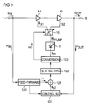
- FIG 9 shows a further embodiment of the invention with an additional feed-forward component to face transient events at the amplifier input.
- ff is derived by a feed-forward unit 124, fed to an adder 125 (or multiplier) and combined with the ongoing actuating variable p2.
Landscapes
- Physics & Mathematics (AREA)
- Electromagnetism (AREA)
- Engineering & Computer Science (AREA)
- Plasma & Fusion (AREA)
- Optics & Photonics (AREA)
- Computer Networks & Wireless Communication (AREA)
- Signal Processing (AREA)
- Lasers (AREA)
Claims (12)
- Procédé de commande d'un amplificateur à fibre optique avec un premier étage d'amplificateur (A1) et un deuxième étage d'amplificateur (A2), pompés par une source unique de lumière de pompe (11) générant un signal de pompe primaire (SPUMP), qui est séparé conformément à un facteur de séparation (α) en un premier signal de pompe (S1) pompant le premier étage d'amplificateur (A1) et un deuxième signal de pompe (S2) restant pompant le deuxième étage d'amplificateur (A2),
comprenant les étapes de
détermination d'une variable primaire d'actionnement (p2) pour commander la deuxième puissance de pompe (P2) du deuxième signal de pompe (S2) et donc la puissance de sortie (POUT) de l'amplificateur lorsque le deuxième étage d'amplificateur est opéré à un régime saturé,
ajustement de la puissance totale de pompe (PPUMP) du signal de pompe primaire (SPUMP) conformément à ladite variable primaire d'actionnement (p2) déterminée tout en maintenant un facteur de séparation maximum (αMAX) si la puissance totale de pompe (PPUMP) du signal de pompe primaire (SPUMP) est strictement inférieure à la puissance totale de pompe maximum disponible (PPMAX) du signal de pompe primaire (SPUMP), et
ajustement du facteur de séparation (α) du séparateur accordable (10) conformément à ladite variable primaire d'actionnement (p2) déterminée si la puissance totale de pompe (PPUMP) est égale à la puissance totale de pompe maximum disponible (PPMAX) du signal de pompe primaire (SPUMP). - Procédé selon la revendication 1,
comprenant les étapes de
calcul de variables secondaires d'actionnement (p, α) conformément à ladite variable primaire d'actionnement (p2) déterminant la puissance de pompe (PPUMP) du signal de pompe primaire (SPUMP) et au facteur de séparation (α),
conversion de ces variables secondaires d'actionnement (p, α) en signaux de commande (pc, αc) électriques, et
ajustement de la puissance totale de pompe (PPUMP) de la source de lumière de pompe (11) et du facteur de séparation (α) du séparateur accordable (10) conformément auxdits signaux de commande (pc, αc). - Procédé selon la revendication 1 ou 2,
comprenant les étapes de
détermination de la puissance de sortie (POUT) du signal de sortie (SOUT) d'amplificateur,
comparaison d'une valeur de référence (PTAR) avec la puissance de sortie (POUT),
génération de la variable primaire d'actionnement (p2) conformément à une différence (Δp = PTAR - POUT) de la valeur de référence (PTAR) et de la puissance de sortie (POUT). - Procédé selon la revendication 1, 2 ou 3,
comprenant les étapes de
comparaison de la puissance maximum de pompe (PPMAX) avec la puissance de pompe actuelle (PPUMP) ou
comparaison d'une valeur de référence de puissance totale de pompe (PPMAX) avec une valeur de puissance totale de pompe calculée (p2/ (1 - a)), et
génération des variables secondaires d'actionnement (pc, αc) conformément à un résultat de comparaison de la valeur de référence de puissance de pompe (PMAX) et de la valeur de référence de puissance de pompe calculée (p2/(1 - α)). - Procédé selon la revendication 4,
comprenant l'étape de
combinaison d'un composant de commande de correction aval (ff), obtenu à partir d'un signal d'entrée (SIN), avec la variable primaire d'actionnement (p2) déterminant la puissance de sortie (POUT) du signal de sortie (SOUT). - Procédé selon l'une des revendications 1 à 5,
comprenant les étapes de
contrôle si la puissance totale de pompe (PPUMP) est inférieure à la puissance maximum de pompe (PPMAX) et si le facteur de séparation (α) est inférieur au facteur de séparation maximum (αMAX) et
augmentation de la puissance totale de pompe (PPUMP) et du facteur de séparation (α) jusqu'à ce qu'une ligne de commande caractéristique (f(P), f(α)) soit obtenue si les deux conditions sont remplies. - Amplificateur optique avec au moins deux étages d'amplificateur (AS1, AS2), contenant une source unique de lumière de pompe (11) générant un signal de pompe primaire (SPUMP), un séparateur (10) divisant ledit signal de pompe primaire (SPUMP) conformément à un facteur de séparation (α) en un premier signal de pompe (S1) alimenté dans un premier étage d'amplificateur (AS1) et un deuxième signal de pompe (S2) restant alimenté dans un deuxième étage d'amplificateur (AS2), et une unité de commande surveillant la puissance de sortie (POUT) de l'amplificateur et commandant le signal de pompe primaire (SPUMP),
caractérisé par
un séparateur accordable (10) ayant un facteur de séparation (α) variable et
un circuit de commande (12) conçu pour
déterminer une variable primaire d'actionnement (p2) pour commander la deuxième puissance de pompe (P2) du deuxième signal de pompe (S2) et donc la puissance de sortie (POUT) de l'amplificateur lorsque le deuxième étage d'amplificateur est opéré à un régime saturé,
ajuster la puissance totale de pompe (PPUMP) du signal de pompe primaire (SPUMP) conformément à ladite variable primaire d'actionnement (p2) déterminée tout en maintenant un facteur de séparation maximum (αMAX) si la puissance totale de pompe (PPUMP) du signal de pompe primaire (SPUMP) est strictement inférieure à une puissance totale de pompe maximum (PPMAX) du signal de pompe primaire (SPUMP), et
ajuster le facteur de séparation (α) du séparateur accordable (10) conformément à ladite variable primaire d'actionnement (p2) déterminée si la puissance totale de pompe (PPUMP) est égale à la puissance totale de pompe maximum (PPMAX) du signal de pompe primaire (SPUMP). - Amplificateur optique selon la revendication 7,
caractérisé par
l'unité de commande (12) modifiée conçue pour
calculer des variables secondaires d'actionnement (p, α) conformément à ladite variable primaire d'actionnement (p2) déterminant la puissance de pompe (PPUMP) du signal de pompe primaire (SPUMP) et au facteur de séparation (α),
convertir ces variables secondaires d'actionnement (p, α) en signaux de commande (pc, αc) électriques, et
ajuster la puissance totale de pompe (PPUMP) de la source de lumière de pompe (11) et le facteur de séparation (α) du séparateur accordable (10) conformément auxdits signaux de commande (pc, αc). - Amplificateur optique selon la revendication 7 ou 8, caractérisé par l'unité de commande (12) modifiée conçue pour
déterminer la puissance de sortie (POUT) de l'amplificateur,
comparer une valeur de référence (PTAR) avec la puissance de sortie (POUT), et
générer la variable primaire d'actionnement (p2) conformément à une différence (Δp = PTAR - POUT) de la valeur de référence (PTAR) et de la puissance de sortie (POUT). - Amplificateur optique selon la revendication 7, 8 ou 9, caractérisé par
l'unité de commande (12) modifiée conçue pour
comparer la puissance maximum de pompe (PPUMPMAX) avec la puissance de pompe (PPUMP) ou
comparer une valeur de référence de puissance totale de pompe (PPMAX) avec une valeur de puissance totale de pompe calculée (p2/ (1 - a)), et
générer les variables secondaires d'actionnement (pc, αc) conformément à un résultat de comparaison. - Amplificateur optique selon l'une des revendications 7 à 10,
caractérisé par
une unité de correction aval (124) connectée à l'entrée (1) d'amplificateur par l'intermédiaire d'un premier séparateur (2) et d'un premier convertisseur optique-électrique (8) surveillant un signal d'entrée (SIN) et générant un composant de commande de correction aval (ff) à partir d'une variation de puissance d'un signal d'entrée (SIN) et alimentant le composant de commande de correction aval (ff) dans l'unité de commande (12). - Amplificateur optique selon l'une des revendications 7 à 11,
dans lequel
des parties passives de l'amplificateur sont intégrées sur une puce à circuits optiques planaires.
Priority Applications (5)
| Application Number | Priority Date | Filing Date | Title |
|---|---|---|---|
| AT08004729T ATE509439T1 (de) | 2008-03-13 | 2008-03-13 | Verfahren zur steuerung eines edfa-verstärkers (erbium doped fibre amplifier) und verstärkeranordnung |
| EP08004729A EP2101426B1 (fr) | 2008-03-13 | 2008-03-13 | Procédé de contrôle d'amplificateur optique à fibre dopée à l'erbium (EDFA) et agencement d'amplificateur |
| US12/922,198 US8493652B2 (en) | 2008-03-13 | 2009-03-11 | Method for controlling an erbium doped fiber amplifier (EDFA) and amplifier arrangement |
| PCT/EP2009/052822 WO2009112504A1 (fr) | 2008-03-13 | 2009-03-11 | Procédé de commande d'amplificateur à fibre dopée à l'erbium (edfa) et agencement d'amplificateur |
| CN200980108742.3A CN101971531B (zh) | 2008-03-13 | 2009-03-11 | 用于控制掺铒光纤放大器(edfa)以及放大器装置的方法 |
Applications Claiming Priority (1)
| Application Number | Priority Date | Filing Date | Title |
|---|---|---|---|
| EP08004729A EP2101426B1 (fr) | 2008-03-13 | 2008-03-13 | Procédé de contrôle d'amplificateur optique à fibre dopée à l'erbium (EDFA) et agencement d'amplificateur |
Publications (2)
| Publication Number | Publication Date |
|---|---|
| EP2101426A1 EP2101426A1 (fr) | 2009-09-16 |
| EP2101426B1 true EP2101426B1 (fr) | 2011-05-11 |
Family
ID=39643918
Family Applications (1)
| Application Number | Title | Priority Date | Filing Date |
|---|---|---|---|
| EP08004729A Active EP2101426B1 (fr) | 2008-03-13 | 2008-03-13 | Procédé de contrôle d'amplificateur optique à fibre dopée à l'erbium (EDFA) et agencement d'amplificateur |
Country Status (5)
| Country | Link |
|---|---|
| US (1) | US8493652B2 (fr) |
| EP (1) | EP2101426B1 (fr) |
| CN (1) | CN101971531B (fr) |
| AT (1) | ATE509439T1 (fr) |
| WO (1) | WO2009112504A1 (fr) |
Families Citing this family (12)
| Publication number | Priority date | Publication date | Assignee | Title |
|---|---|---|---|---|
| GB201008003D0 (en) * | 2010-05-13 | 2010-06-30 | Oclaro Technology Plc | Optical Amplifiers |
| US9083142B2 (en) * | 2010-10-22 | 2015-07-14 | Nec Corporation | Excitation light distribution device, excitation light distribution method, optical amplification system and node device |
| US8941911B2 (en) * | 2012-11-16 | 2015-01-27 | Viscore Technologies Inc. | Methods and devices for efficient optical fiber amplifiers |
| CN105068355B (zh) * | 2015-08-26 | 2018-12-14 | 武汉光迅科技股份有限公司 | 一种单级多泵光纤放大器的控制系统和控制方法 |
| CN105471508A (zh) * | 2015-12-30 | 2016-04-06 | 桂林创研科技有限公司 | 一种光放大系统 |
| US20180084320A1 (en) * | 2016-09-21 | 2018-03-22 | Lumentum Operations Llc | Programmable multicast switch |
| US20180351317A1 (en) * | 2017-04-27 | 2018-12-06 | Analog Photonics LLC | On-chip optical gain circuits |
| US11362477B2 (en) * | 2017-09-29 | 2022-06-14 | Fujikura Ltd. | Fiber laser system and control method therefor |
| US11870208B2 (en) | 2018-03-09 | 2024-01-09 | Nec Corporation | Optical fiber amplifier, optical fiber amplifier control method, and transmission system |
| CN109543314B (zh) * | 2018-11-27 | 2022-04-15 | 苏州大学 | 一种光纤升级后弹性光网络的光放大器重排列方法 |
| US11309678B2 (en) * | 2019-10-09 | 2022-04-19 | Molex, Llc | Spectrum and power tunable ASE light source |
| WO2023183078A2 (fr) | 2022-03-17 | 2023-09-28 | Exciting Technology LLC | Système, procédé et appareil de formation d'image de vibration holographique numérique avec correction de phase de système intégrée |
Family Cites Families (10)
| Publication number | Priority date | Publication date | Assignee | Title |
|---|---|---|---|---|
| US5253104A (en) | 1992-09-15 | 1993-10-12 | At&T Bell Laboratories | Balanced optical amplifier |
| JP2546484B2 (ja) | 1993-04-13 | 1996-10-23 | 日本電気株式会社 | 光ファイバアンプ装置 |
| SE509968C2 (sv) * | 1997-02-14 | 1999-03-29 | Ericsson Telefon Ab L M | Optisk förstärkare med variabel förstärkning |
| US6335823B2 (en) * | 1997-10-17 | 2002-01-01 | Fujitsu Limited | Optical amplifier for use in optical communications equipment |
| US5991069A (en) | 1998-01-22 | 1999-11-23 | Tyco Submarine Systems, Ltd. | Split-pumped dual stage optical fiber amplifier |
| JP2001196671A (ja) * | 2000-01-06 | 2001-07-19 | Nec Corp | 波長多重伝送用光ファイバ増幅器 |
| US6377394B1 (en) | 2000-03-30 | 2002-04-23 | Nortel Networks Limited | Optical amplifier gain control |
| DE102005031897B4 (de) | 2005-07-07 | 2007-10-25 | Siemens Ag | Mehrstufiger Faserverstärker |
| ATE434846T1 (de) | 2005-07-07 | 2009-07-15 | Nokia Siemens Networks Gmbh | Mehrstufiger faserverstärker und verfahren zur anpassung einer pumpleistung eines mehrstufigen faserverstärkers |
| US8233214B2 (en) * | 2008-02-13 | 2012-07-31 | Maxim Bolshtyansky | Optical fiber amplifier and a control method therefor |
-
2008
- 2008-03-13 AT AT08004729T patent/ATE509439T1/de not_active IP Right Cessation
- 2008-03-13 EP EP08004729A patent/EP2101426B1/fr active Active
-
2009
- 2009-03-11 US US12/922,198 patent/US8493652B2/en active Active
- 2009-03-11 WO PCT/EP2009/052822 patent/WO2009112504A1/fr not_active Ceased
- 2009-03-11 CN CN200980108742.3A patent/CN101971531B/zh active Active
Also Published As
| Publication number | Publication date |
|---|---|
| WO2009112504A1 (fr) | 2009-09-17 |
| CN101971531A (zh) | 2011-02-09 |
| EP2101426A1 (fr) | 2009-09-16 |
| CN101971531B (zh) | 2014-08-27 |
| ATE509439T1 (de) | 2011-05-15 |
| US20110085230A1 (en) | 2011-04-14 |
| US8493652B2 (en) | 2013-07-23 |
Similar Documents
| Publication | Publication Date | Title |
|---|---|---|
| EP2101426B1 (fr) | Procédé de contrôle d'amplificateur optique à fibre dopée à l'erbium (EDFA) et agencement d'amplificateur | |
| CN1917307B (zh) | 放大多波长光的光放大器 | |
| US7085043B2 (en) | Optical amplifier | |
| KR100462029B1 (ko) | 광섬유 증폭기 및 이의 제어 방법 | |
| US6611641B2 (en) | Method and apparatus for a highly efficient, high performance optical amplifier | |
| US6043930A (en) | Optical amplifier and optical fiber applicable to optical amplifier | |
| EP0570941B1 (fr) | Amplificateur à fibre optique | |
| US20020008902A1 (en) | Wavelength division multiplexing optical fiber amplifier | |
| US8164826B2 (en) | Multi-stage optical amplifier and method of controlling the same | |
| KR20000024997A (ko) | 채널당 출력파워가 일정한 파장분할다중화광섬유증폭기b | |
| EP1493211B1 (fr) | Amplificateurs optiques | |
| US6980357B2 (en) | Optical amplifier apparatus and method | |
| Feng et al. | A simple control algorithm for wide-band channel-power clamped EDFA | |
| Rapp | Transient behavior of EDFA stages using pump power splitting or pump bypass technique | |
| KR100581058B1 (ko) | 광섬유 증폭기 | |
| US20020186458A1 (en) | Dynamically controlled optical amplifier module | |
| Qela et al. | Multi-channel dynamically gain controlled optical amplifier | |
| HK1121301A (en) | Multi-stage optical amplifier and method of controlling the same | |
| JP2001196673A (ja) | 光ファイバ増幅器 | |
| HK1036891B (en) | Optical fibre amplifier having a controlled gain |
Legal Events
| Date | Code | Title | Description |
|---|---|---|---|
| PUAI | Public reference made under article 153(3) epc to a published international application that has entered the european phase |
Free format text: ORIGINAL CODE: 0009012 |
|
| AK | Designated contracting states |
Kind code of ref document: A1 Designated state(s): AT BE BG CH CY CZ DE DK EE ES FI FR GB GR HR HU IE IS IT LI LT LU LV MC MT NL NO PL PT RO SE SI SK TR |
|
| AX | Request for extension of the european patent |
Extension state: AL BA MK RS |
|
| 17P | Request for examination filed |
Effective date: 20100316 |
|
| 17Q | First examination report despatched |
Effective date: 20100408 |
|
| AKX | Designation fees paid |
Designated state(s): AT BE BG CH CY CZ DE DK EE ES FI FR GB GR HR HU IE IS IT LI LT LU LV MC MT NL NO PL PT RO SE SI SK TR |
|
| GRAP | Despatch of communication of intention to grant a patent |
Free format text: ORIGINAL CODE: EPIDOSNIGR1 |
|
| GRAS | Grant fee paid |
Free format text: ORIGINAL CODE: EPIDOSNIGR3 |
|
| GRAA | (expected) grant |
Free format text: ORIGINAL CODE: 0009210 |
|
| AK | Designated contracting states |
Kind code of ref document: B1 Designated state(s): AT BE BG CH CY CZ DE DK EE ES FI FR GB GR HR HU IE IS IT LI LT LU LV MC MT NL NO PL PT RO SE SI SK TR |
|
| REG | Reference to a national code |
Ref country code: GB Ref legal event code: FG4D |
|
| REG | Reference to a national code |
Ref country code: CH Ref legal event code: EP |
|
| REG | Reference to a national code |
Ref country code: IE Ref legal event code: FG4D |
|
| REG | Reference to a national code |
Ref country code: DE Ref legal event code: R096 Ref document number: 602008006845 Country of ref document: DE Effective date: 20110622 |
|
| REG | Reference to a national code |
Ref country code: SE Ref legal event code: TRGR |
|
| REG | Reference to a national code |
Ref country code: NL Ref legal event code: VDEP Effective date: 20110511 |
|
| PG25 | Lapsed in a contracting state [announced via postgrant information from national office to epo] |
Ref country code: PT Free format text: LAPSE BECAUSE OF FAILURE TO SUBMIT A TRANSLATION OF THE DESCRIPTION OR TO PAY THE FEE WITHIN THE PRESCRIBED TIME-LIMIT Effective date: 20110912 Ref country code: NO Free format text: LAPSE BECAUSE OF FAILURE TO SUBMIT A TRANSLATION OF THE DESCRIPTION OR TO PAY THE FEE WITHIN THE PRESCRIBED TIME-LIMIT Effective date: 20110811 Ref country code: LT Free format text: LAPSE BECAUSE OF FAILURE TO SUBMIT A TRANSLATION OF THE DESCRIPTION OR TO PAY THE FEE WITHIN THE PRESCRIBED TIME-LIMIT Effective date: 20110511 |
|
| PG25 | Lapsed in a contracting state [announced via postgrant information from national office to epo] |
Ref country code: BE Free format text: LAPSE BECAUSE OF FAILURE TO SUBMIT A TRANSLATION OF THE DESCRIPTION OR TO PAY THE FEE WITHIN THE PRESCRIBED TIME-LIMIT Effective date: 20110511 Ref country code: IS Free format text: LAPSE BECAUSE OF FAILURE TO SUBMIT A TRANSLATION OF THE DESCRIPTION OR TO PAY THE FEE WITHIN THE PRESCRIBED TIME-LIMIT Effective date: 20110911 Ref country code: GR Free format text: LAPSE BECAUSE OF FAILURE TO SUBMIT A TRANSLATION OF THE DESCRIPTION OR TO PAY THE FEE WITHIN THE PRESCRIBED TIME-LIMIT Effective date: 20110812 Ref country code: SI Free format text: LAPSE BECAUSE OF FAILURE TO SUBMIT A TRANSLATION OF THE DESCRIPTION OR TO PAY THE FEE WITHIN THE PRESCRIBED TIME-LIMIT Effective date: 20110511 Ref country code: ES Free format text: LAPSE BECAUSE OF FAILURE TO SUBMIT A TRANSLATION OF THE DESCRIPTION OR TO PAY THE FEE WITHIN THE PRESCRIBED TIME-LIMIT Effective date: 20110822 Ref country code: LV Free format text: LAPSE BECAUSE OF FAILURE TO SUBMIT A TRANSLATION OF THE DESCRIPTION OR TO PAY THE FEE WITHIN THE PRESCRIBED TIME-LIMIT Effective date: 20110511 Ref country code: FI Free format text: LAPSE BECAUSE OF FAILURE TO SUBMIT A TRANSLATION OF THE DESCRIPTION OR TO PAY THE FEE WITHIN THE PRESCRIBED TIME-LIMIT Effective date: 20110511 Ref country code: CY Free format text: LAPSE BECAUSE OF FAILURE TO SUBMIT A TRANSLATION OF THE DESCRIPTION OR TO PAY THE FEE WITHIN THE PRESCRIBED TIME-LIMIT Effective date: 20110511 Ref country code: AT Free format text: LAPSE BECAUSE OF FAILURE TO SUBMIT A TRANSLATION OF THE DESCRIPTION OR TO PAY THE FEE WITHIN THE PRESCRIBED TIME-LIMIT Effective date: 20110511 |
|
| PG25 | Lapsed in a contracting state [announced via postgrant information from national office to epo] |
Ref country code: NL Free format text: LAPSE BECAUSE OF FAILURE TO SUBMIT A TRANSLATION OF THE DESCRIPTION OR TO PAY THE FEE WITHIN THE PRESCRIBED TIME-LIMIT Effective date: 20110511 |
|
| PG25 | Lapsed in a contracting state [announced via postgrant information from national office to epo] |
Ref country code: EE Free format text: LAPSE BECAUSE OF FAILURE TO SUBMIT A TRANSLATION OF THE DESCRIPTION OR TO PAY THE FEE WITHIN THE PRESCRIBED TIME-LIMIT Effective date: 20110511 Ref country code: CZ Free format text: LAPSE BECAUSE OF FAILURE TO SUBMIT A TRANSLATION OF THE DESCRIPTION OR TO PAY THE FEE WITHIN THE PRESCRIBED TIME-LIMIT Effective date: 20110511 |
|
| PG25 | Lapsed in a contracting state [announced via postgrant information from national office to epo] |
Ref country code: PL Free format text: LAPSE BECAUSE OF FAILURE TO SUBMIT A TRANSLATION OF THE DESCRIPTION OR TO PAY THE FEE WITHIN THE PRESCRIBED TIME-LIMIT Effective date: 20110511 Ref country code: DK Free format text: LAPSE BECAUSE OF FAILURE TO SUBMIT A TRANSLATION OF THE DESCRIPTION OR TO PAY THE FEE WITHIN THE PRESCRIBED TIME-LIMIT Effective date: 20110511 Ref country code: SK Free format text: LAPSE BECAUSE OF FAILURE TO SUBMIT A TRANSLATION OF THE DESCRIPTION OR TO PAY THE FEE WITHIN THE PRESCRIBED TIME-LIMIT Effective date: 20110511 Ref country code: RO Free format text: LAPSE BECAUSE OF FAILURE TO SUBMIT A TRANSLATION OF THE DESCRIPTION OR TO PAY THE FEE WITHIN THE PRESCRIBED TIME-LIMIT Effective date: 20110511 |
|
| PLBE | No opposition filed within time limit |
Free format text: ORIGINAL CODE: 0009261 |
|
| STAA | Information on the status of an ep patent application or granted ep patent |
Free format text: STATUS: NO OPPOSITION FILED WITHIN TIME LIMIT |
|
| 26N | No opposition filed |
Effective date: 20120214 |
|
| PG25 | Lapsed in a contracting state [announced via postgrant information from national office to epo] |
Ref country code: HR Free format text: LAPSE BECAUSE OF FAILURE TO SUBMIT A TRANSLATION OF THE DESCRIPTION OR TO PAY THE FEE WITHIN THE PRESCRIBED TIME-LIMIT Effective date: 20111123 Ref country code: IT Free format text: LAPSE BECAUSE OF FAILURE TO SUBMIT A TRANSLATION OF THE DESCRIPTION OR TO PAY THE FEE WITHIN THE PRESCRIBED TIME-LIMIT Effective date: 20110511 |
|
| REG | Reference to a national code |
Ref country code: DE Ref legal event code: R097 Ref document number: 602008006845 Country of ref document: DE Effective date: 20120214 |
|
| PG25 | Lapsed in a contracting state [announced via postgrant information from national office to epo] |
Ref country code: MC Free format text: LAPSE BECAUSE OF NON-PAYMENT OF DUE FEES Effective date: 20120331 |
|
| REG | Reference to a national code |
Ref country code: CH Ref legal event code: PL |
|
| REG | Reference to a national code |
Ref country code: IE Ref legal event code: MM4A |
|
| PG25 | Lapsed in a contracting state [announced via postgrant information from national office to epo] |
Ref country code: CH Free format text: LAPSE BECAUSE OF NON-PAYMENT OF DUE FEES Effective date: 20120331 Ref country code: IE Free format text: LAPSE BECAUSE OF NON-PAYMENT OF DUE FEES Effective date: 20120313 Ref country code: LI Free format text: LAPSE BECAUSE OF NON-PAYMENT OF DUE FEES Effective date: 20120331 |
|
| PG25 | Lapsed in a contracting state [announced via postgrant information from national office to epo] |
Ref country code: BG Free format text: LAPSE BECAUSE OF FAILURE TO SUBMIT A TRANSLATION OF THE DESCRIPTION OR TO PAY THE FEE WITHIN THE PRESCRIBED TIME-LIMIT Effective date: 20110811 |
|
| PG25 | Lapsed in a contracting state [announced via postgrant information from national office to epo] |
Ref country code: MT Free format text: LAPSE BECAUSE OF FAILURE TO SUBMIT A TRANSLATION OF THE DESCRIPTION OR TO PAY THE FEE WITHIN THE PRESCRIBED TIME-LIMIT Effective date: 20110511 |
|
| REG | Reference to a national code |
Ref country code: DE Ref legal event code: R082 Ref document number: 602008006845 Country of ref document: DE Representative=s name: BOEHMERT & BOEHMERT, DE |
|
| PG25 | Lapsed in a contracting state [announced via postgrant information from national office to epo] |
Ref country code: HR Free format text: LAPSE BECAUSE OF FAILURE TO SUBMIT A TRANSLATION OF THE DESCRIPTION OR TO PAY THE FEE WITHIN THE PRESCRIBED TIME-LIMIT Effective date: 20110511 |
|
| REG | Reference to a national code |
Ref country code: DE Ref legal event code: R082 Ref document number: 602008006845 Country of ref document: DE Representative=s name: BOEHMERT & BOEHMERT, DE Effective date: 20131112 Ref country code: DE Ref legal event code: R081 Ref document number: 602008006845 Country of ref document: DE Owner name: XIEON NETWORKS S.A.R.L., LU Free format text: FORMER OWNER: NOKIA SIEMENS NETWORKS OY, ESPOO, FI Effective date: 20131112 Ref country code: DE Ref legal event code: R082 Ref document number: 602008006845 Country of ref document: DE Representative=s name: BOEHMERT & BOEHMERT ANWALTSPARTNERSCHAFT MBB -, DE Effective date: 20131112 |
|
| REG | Reference to a national code |
Ref country code: GB Ref legal event code: 732E Free format text: REGISTERED BETWEEN 20131212 AND 20131218 |
|
| REG | Reference to a national code |
Ref country code: GB Ref legal event code: 732E Free format text: REGISTERED BETWEEN 20140130 AND 20140205 |
|
| PG25 | Lapsed in a contracting state [announced via postgrant information from national office to epo] |
Ref country code: TR Free format text: LAPSE BECAUSE OF FAILURE TO SUBMIT A TRANSLATION OF THE DESCRIPTION OR TO PAY THE FEE WITHIN THE PRESCRIBED TIME-LIMIT Effective date: 20110511 |
|
| REG | Reference to a national code |
Ref country code: FR Ref legal event code: GC Effective date: 20140408 Ref country code: FR Ref legal event code: TP Owner name: XIEON NETWORKS S.A.R.L., LU Effective date: 20140408 |
|
| PG25 | Lapsed in a contracting state [announced via postgrant information from national office to epo] |
Ref country code: LU Free format text: LAPSE BECAUSE OF NON-PAYMENT OF DUE FEES Effective date: 20120313 |
|
| PG25 | Lapsed in a contracting state [announced via postgrant information from national office to epo] |
Ref country code: HU Free format text: LAPSE BECAUSE OF FAILURE TO SUBMIT A TRANSLATION OF THE DESCRIPTION OR TO PAY THE FEE WITHIN THE PRESCRIBED TIME-LIMIT Effective date: 20080313 |
|
| REG | Reference to a national code |
Ref country code: DE Ref legal event code: R079 Ref document number: 602008006845 Country of ref document: DE Free format text: PREVIOUS MAIN CLASS: H04B0010170000 Ipc: H04B0010291000 |
|
| REG | Reference to a national code |
Ref country code: DE Ref legal event code: R079 Ref document number: 602008006845 Country of ref document: DE Free format text: PREVIOUS MAIN CLASS: H04B0010170000 Ipc: H04B0010291000 Effective date: 20141124 |
|
| REG | Reference to a national code |
Ref country code: FR Ref legal event code: GC Effective date: 20150922 |
|
| REG | Reference to a national code |
Ref country code: FR Ref legal event code: PLFP Year of fee payment: 9 |
|
| PGFP | Annual fee paid to national office [announced via postgrant information from national office to epo] |
Ref country code: SE Payment date: 20160321 Year of fee payment: 9 |
|
| REG | Reference to a national code |
Ref country code: FR Ref legal event code: PLFP Year of fee payment: 10 |
|
| REG | Reference to a national code |
Ref country code: SE Ref legal event code: EUG |
|
| PG25 | Lapsed in a contracting state [announced via postgrant information from national office to epo] |
Ref country code: SE Free format text: LAPSE BECAUSE OF NON-PAYMENT OF DUE FEES Effective date: 20170314 |
|
| REG | Reference to a national code |
Ref country code: FR Ref legal event code: PLFP Year of fee payment: 11 |
|
| P01 | Opt-out of the competence of the unified patent court (upc) registered |
Effective date: 20230526 |
|
| PGFP | Annual fee paid to national office [announced via postgrant information from national office to epo] |
Ref country code: GB Payment date: 20260202 Year of fee payment: 19 |
|
| PGFP | Annual fee paid to national office [announced via postgrant information from national office to epo] |
Ref country code: DE Payment date: 20260204 Year of fee payment: 19 |
|
| PGFP | Annual fee paid to national office [announced via postgrant information from national office to epo] |
Ref country code: FR Payment date: 20260209 Year of fee payment: 19 |