EP2101705B1 - Chariot de transfert - Google Patents
Chariot de transfert Download PDFInfo
- Publication number
- EP2101705B1 EP2101705B1 EP07848486A EP07848486A EP2101705B1 EP 2101705 B1 EP2101705 B1 EP 2101705B1 EP 07848486 A EP07848486 A EP 07848486A EP 07848486 A EP07848486 A EP 07848486A EP 2101705 B1 EP2101705 B1 EP 2101705B1
- Authority
- EP
- European Patent Office
- Prior art keywords
- sheath
- support member
- transfer trolley
- lifting
- tongues
- Prior art date
- Legal status (The legal status is an assumption and is not a legal conclusion. Google has not performed a legal analysis and makes no representation as to the accuracy of the status listed.)
- Not-in-force
Links
- 238000000034 method Methods 0.000 claims description 30
- 239000012530 fluid Substances 0.000 claims description 14
- 210000002105 tongue Anatomy 0.000 description 123
- 239000000463 material Substances 0.000 description 14
- 230000007246 mechanism Effects 0.000 description 12
- 230000006378 damage Effects 0.000 description 4
- 229920001971 elastomer Polymers 0.000 description 4
- 239000005060 rubber Substances 0.000 description 4
- 238000007789 sealing Methods 0.000 description 3
- 206010052428 Wound Diseases 0.000 description 2
- 208000027418 Wounds and injury Diseases 0.000 description 2
- 238000002788 crimping Methods 0.000 description 2
- 230000000694 effects Effects 0.000 description 2
- 239000007788 liquid Substances 0.000 description 2
- TVEXGJYMHHTVKP-UHFFFAOYSA-N 6-oxabicyclo[3.2.1]oct-3-en-7-one Chemical compound C1C2C(=O)OC1C=CC2 TVEXGJYMHHTVKP-UHFFFAOYSA-N 0.000 description 1
- 208000025940 Back injury Diseases 0.000 description 1
- 239000004677 Nylon Substances 0.000 description 1
- 238000004026 adhesive bonding Methods 0.000 description 1
- 239000000919 ceramic Substances 0.000 description 1
- 238000004891 communication Methods 0.000 description 1
- 230000003247 decreasing effect Effects 0.000 description 1
- 239000003814 drug Substances 0.000 description 1
- 239000002360 explosive Substances 0.000 description 1
- 208000015181 infectious disease Diseases 0.000 description 1
- 208000014674 injury Diseases 0.000 description 1
- 229920001778 nylon Polymers 0.000 description 1
- 239000004033 plastic Substances 0.000 description 1
- 229920003023 plastic Polymers 0.000 description 1
- 229920002635 polyurethane Polymers 0.000 description 1
- 239000004814 polyurethane Substances 0.000 description 1
- 230000036544 posture Effects 0.000 description 1
- 230000001681 protective effect Effects 0.000 description 1
- 230000001007 puffing effect Effects 0.000 description 1
- 238000005086 pumping Methods 0.000 description 1
- 239000012857 radioactive material Substances 0.000 description 1
- 238000005096 rolling process Methods 0.000 description 1
- 229920003051 synthetic elastomer Polymers 0.000 description 1
- 239000005061 synthetic rubber Substances 0.000 description 1
Images


Classifications
-
- A—HUMAN NECESSITIES
- A61—MEDICAL OR VETERINARY SCIENCE; HYGIENE
- A61G—TRANSPORT, PERSONAL CONVEYANCES, OR ACCOMMODATION SPECIALLY ADAPTED FOR PATIENTS OR DISABLED PERSONS; OPERATING TABLES OR CHAIRS; CHAIRS FOR DENTISTRY; FUNERAL DEVICES
- A61G7/00—Beds specially adapted for nursing; Devices for lifting patients or disabled persons
- A61G7/10—Devices for lifting patients or disabled persons, e.g. special adaptations of hoists thereto
- A61G7/1049—Attachment, suspending or supporting means for patients
- A61G7/1057—Supported platforms, frames or sheets for patient in lying position
-
- A—HUMAN NECESSITIES
- A61—MEDICAL OR VETERINARY SCIENCE; HYGIENE
- A61G—TRANSPORT, PERSONAL CONVEYANCES, OR ACCOMMODATION SPECIALLY ADAPTED FOR PATIENTS OR DISABLED PERSONS; OPERATING TABLES OR CHAIRS; CHAIRS FOR DENTISTRY; FUNERAL DEVICES
- A61G2200/00—Information related to the kind of patient or his position
- A61G2200/10—Type of patient
- A61G2200/16—Type of patient bariatric, e.g. heavy or obese
-
- A—HUMAN NECESSITIES
- A61—MEDICAL OR VETERINARY SCIENCE; HYGIENE
- A61G—TRANSPORT, PERSONAL CONVEYANCES, OR ACCOMMODATION SPECIALLY ADAPTED FOR PATIENTS OR DISABLED PERSONS; OPERATING TABLES OR CHAIRS; CHAIRS FOR DENTISTRY; FUNERAL DEVICES
- A61G7/00—Beds specially adapted for nursing; Devices for lifting patients or disabled persons
- A61G7/10—Devices for lifting patients or disabled persons, e.g. special adaptations of hoists thereto
- A61G7/1013—Lifting of patients by
- A61G7/1019—Vertical extending columns or mechanisms
-
- A—HUMAN NECESSITIES
- A61—MEDICAL OR VETERINARY SCIENCE; HYGIENE
- A61G—TRANSPORT, PERSONAL CONVEYANCES, OR ACCOMMODATION SPECIALLY ADAPTED FOR PATIENTS OR DISABLED PERSONS; OPERATING TABLES OR CHAIRS; CHAIRS FOR DENTISTRY; FUNERAL DEVICES
- A61G7/00—Beds specially adapted for nursing; Devices for lifting patients or disabled persons
- A61G7/10—Devices for lifting patients or disabled persons, e.g. special adaptations of hoists thereto
- A61G7/1013—Lifting of patients by
- A61G7/1021—Inflatable cushions
-
- A—HUMAN NECESSITIES
- A61—MEDICAL OR VETERINARY SCIENCE; HYGIENE
- A61G—TRANSPORT, PERSONAL CONVEYANCES, OR ACCOMMODATION SPECIALLY ADAPTED FOR PATIENTS OR DISABLED PERSONS; OPERATING TABLES OR CHAIRS; CHAIRS FOR DENTISTRY; FUNERAL DEVICES
- A61G7/00—Beds specially adapted for nursing; Devices for lifting patients or disabled persons
- A61G7/10—Devices for lifting patients or disabled persons, e.g. special adaptations of hoists thereto
- A61G7/1025—Lateral movement of patients, e.g. horizontal transfer
- A61G7/1026—Sliding sheets or mats
Definitions
- the present invention relates to a transfer trolley and, more particularly, aspects of the invention relate to a transfer trolley that can be used to lift a load and transfer it to a new location.
- transfer trolleys according to embodiments of the present invention can be used to lift medical patients from a bed or table for transfer to another location.
- embodiments of the invention will be described below in relation to the transfer of medical patients, it would be appreciated that embodiments of the invention can be utilised to transport and transfer other loads, such as delicate items, comprising china, ceramics, explosives, aerospace components or radioactive material.
- a trolley in accordance with aspects of the present invention can also be used to move motor vehicles, such as illegally parked vehicles.
- a transfer trolley according to this document comprises an arm from which a number of rigid tongues extend.
- the rigid tongues generally form a bed-like surface and are capable of supporting a patient.
- the tongues are hollow and could be described as flatted tube-like structures; a hole is located at the free end of each tongue (i.e. the end not connected to the arm).
- Each of the tongues is covered in a resilient sleeve or sheath and contains a plunger within the hollow cavity.
- the sheath is longer than the tongue which it surrounds and the excess material is inserted into the hollow cavity of the tube (where there is a connection between the sheath and the plunger) and also accommodated by a concertina arrangement of part of the sheath on the outside of the tongue.
- a wedge shaped block separates the concertina arrangement on the top surface of the tongue from the rest of the sheath.
- the transfer trolley When it is decided that a patient is to be transferred from a bed, the transfer trolley according to WO91/07158 is manoeuvred into a position next to and parallel with the patient's bed. Compressed air is introduced into the sheaths and this action drives the portion of the sheath contained within the hollow cavity of the tongue outwards through the hole in the free end of the tongue.
- a cylinder of sheath inflates and unfurls in a direction away from the trolley and underneath the patient.
- the trolley is moved towards the patient's bed; thus the wedge shaped section (which remains stationary relative to the patient) is now closer to the arm and this has the effect of puffing the sheaths, with the patient supported thereon, towards the arm so that the portions of the sheaths that support the patient slide over the respective tongues, The weight of the patient is now supported by the tongues and not by the inflated sheath.
- NL9101806 discloses a preinflated lifting element comprising a support member and a tubular inflated cushion.
- the support member may be pushed through the cushion in order to move the lifting element beneath a load.
- US4084275 discloses a protective cover for a lifting device which may be rolled into a position under an object to affect lifting thereof and the method of utilising cover.
- the present invention seeks to ameliorate at least some of the problems associated with the prior art.
- an aspect to the present invention provides a lifting element, as claimed, for use with a transfer trolley, the element comprising: a support member having a support surface, a hollow cavity extending along a length of the support member (3), and a sheath attached to the support member such that, in an initial configuration, a first portion of the support surface is covered by the sheath and a second portion thereof is uncovered, wherein the hollow cavity is configured to receive an excess portion of the sheath, the sheath is operable to be inflated so as to cause the sheath to extend and evert, insinuating itself under a load in order to support the load, and, after inflation, the support member and the sheath may be moved with respect to each other so that the support member extends further into the sheath, a portion of the sheath is moved out of the hollow cavity, the second portion of the support surface is covered by the sheath and the support surface at least partially supports the load.
- the sheath is fixedly attached to a main body section of the support member.
- the sheath is attached to a main body section of the support member by a sliding seal attachment arrangement.
- the support member has a distal end and a proximal end; the sheath is attached to the support member at a securing location which is separated from the proximal end of the member; and, after inflation, the support member and sleeve may be moved with respect to each other so that a portion of the sleeve covers at least a part of the region of the support surface between the securing location and the proximal end of the support member.
- the support member has a distal end and a proximal end; the sheath is attached to the support member by the sliding seal attachment arrangement which is provided between the proximal and distal ends thereof and operable to slide along at least a part of the length of the support member; and, after inflation, the sliding seal attachment arrangement is operable to slide towards the proximal end of the member to allow the load to be at least partially supported by the support member.
- the lifting element further comprises a fluid channel to inflate the sheath.
- the fluid channel is provided within the support member.
- the lifting element further comprises a drawstring attached to the sheath and operable to control an aspect of the inflation or deflation of the sheath.
- Another aspect of the present invention provides a transfer trolley including one or more lifting elements.
- the lifting elements are provided in spaced apart relation to provide an array on which a patient may be placed.
- the transfer trolley further comprises an arrangement for selectively controlling the one or more lifting elements.
- the transfer trolley further comprises a base arrangement including a track and a tower mounted on the track operable to support the one or more lifting elements, wherein the one or more lifting elements can be moved with respect to the base arrangement by moving the tower along the track.
- the lifting elements are supported by one or more arms.
- the lifting elements are supported by a plurality of arms.
- two or more of the plurality of arms are attached to each other by joints.
- the arms are operable to be moved with respect to each other.
- the transfer trolley further comprises an angle adjustment arrangement operable to adjust the angle of the lifting elements with respect to a horizontal plane.
- the lifting elements may be rotated with respect to each other.
- Another aspect of the present invention provides a method of lifting a load utilising a lifting element having a sheath and a support member comprising the steps of: inflating the sheath causing the sheath to insinuate under the load, and moving the sheath and the support member with respect to each other so that the support member extends into the sheath, the excess portion of the sheath is moved out of the hollow cavity and the support member at least partially supports the load.
- a transfer trolley comprising a two or more arms each supporting one or more lifting elements, each element comprising a support member and a sheath attached to the support member and operable to be inflated so as to cause the sheath to extend and evert, insinuating itself under a load in order to support a load, wherein the arms are suitable to be moved with respect to each other from a first configuration to a second configuration.
- the arms are operable to be moved from a first configuration to a second configuration in which the arms are at different angles with respect to each other.
- a transfer trolley 10 includes a frame 1.
- the frame 1 comprises a c-shaped base 4.
- the c-shaped base 4 has a horizontal main beam 5 with a longitudinal axis and two laterally extending horizontal support beams 6,7 - one at either end of the main beam 5 and both extending in a first direction perpendicular to the longitudinal axis thereof.
- the base 4 is typically mounted on four or more wheels or casters 17 to allow for movement of the transfer trolley 10.
- the wheels or casters 17 are preferably provided with locks that can be activated once the transfer trolley 10 is in a desired location to prevent any further and unwanted movement.
- the exact type of wheels or casters 17 utilised will be apparent to a skilled person depending upon the degree and type of movement required for the specific task at hand.
- the base 4 is attached to wheels suitable to run on rails.
- a vertical tower 8 extends from the main beam 5 to a height which is generally less than the height of a hospital bed or table.
- the tower 8 holds a turret 9 telescopically mounted at an upper end of the tower 8, and the height to which the turret 9 extends above the top of the tower 8 (ie. the height of a free end of the turret 9 above the tower 8) can be controlled, for example, hydraulically - although other mounting mechanisms are also envisaged.
- the trolley 10 can be adjusted to accommodate a number of different bed or table heights.
- the base 4 further comprises a track arrangement (not shown) on which the tower 8 is mounted.
- the tower 8 may, therefore, be moved along the track relative to the position of the base 4.
- the track arrangement allows the tower 8 to be moved in a direction parallel to the horizontal support beams 6,7 of the base 4.
- An arm 2 is attached, in a substantially horizontal orientation, to the free upper end of the turret 9 and has a longitudinal axis which is substantially parallel to the longitudinal axis of the main beam 5 of the base 4.
- the arm 2 is supported by one or more rigid support beams (not shown) which are attached to both the arm 2 and the turret 9 and help to support the arm 2 in a generally fixed position relative to the turret 9.
- a plurality of spaced apart tongues, projections, or tines 3 extend from the arm 2 in the first direction and have longitudinal axes which are generally perpendicular to the longitudinal axis of the arm 2.
- the tongues 3 each have an upper support surface and form a slatted transfer shelf, and are securely attached to the arm 2 at one end thereof (ie. a proximal end) such that they are suitable to support the weight of a patient lying across the tongues 3.
- the tongues 3 form a cantilevered transfer shelf.
- the transfer trolley 10 is sufficiently strong to ensure that a patient of a mass up to about 150Kg can be supported on the transfer shelf.
- the transfer shelf of the trolley 10 can support masses of over about 150Kg.
- each tongue 3 has a hollow cavity 11 extending along the length thereof, the cavity 11 having an opening at both the free end 12 (ie. the distal end) and the end attached to the arm 2 (ie. the proximal end). Therefore, each tongue 3 takes the general appearance of a flattened pipe or, indeed, may comprise a substantially cylindrical pipe.
- respective sheaths 13 of flexible material are securely attached to each tongue 3 using a securing mechanism 14.
- the securing mechanism 14 can take a number of different forms but preferably the mechanism comprises a crimping ring or band 14 which is placed around a portion of the sheath 13 and the tongue 3 and subsequently compressed - securing the sheath 13 to the tongue 3.
- a seal is created at the crimping ring 14 (or other securing mechanism) which ensures that there is a substantially airtight seal which prevents any air (or liquid or other fluid) which is pumped into the sheath 13 through the tongue 3 from escaping from the sheath 13 and tongue 3 at the point at which they are secured to one another.
- the securing mechanisms 14 are, when fitted, separated from the proximal ends of each tongue 3, and more preferably are located towards the free ends of each tongue 3. It is envisaged that any suitable securing mechanism 14 may be utilised including but not limited to wire clamps, spring clamps, adhesive bonding, and screw clamps.
- embodiments of the present invention include arrangements where there is a moveable or sliding seal 18 attached to an open end of each sheath 13 and operable to slide or move along a respective tongue 3. During the sliding operation the seal is generally maintained.
- the sliding seal 18 can take any number of different forms which will be apparent to a person skilled in the art.
- one or more rubber skirts could be used either side of a cavity in an annular sealing mechanism 18, the cavity contains a plurality of lubricated balls (not shown).
- the lubricated balls maintain a generally fixed distance between the sealing mechanism 18 and a surface of the tongue 3; the rubber skirts ensure that there is an adequate seal between the sealing mechanism 18 and the tongue 3.
- At least one of the rubber skirts is biased such that pressure applied to the skirt by, for example, a hydraulic fluid, presses the skirt against the tongue 3 and ensures that a seal is maintained.
- a hydraulic fluid presses the skirt against the tongue 3 and ensures that a seal is maintained.
- other materials could be used to form the skirts, not just rubber (for example, synthetic rubber materials, or plastics). This arrangement can be seen in Figure 3a .
- Each sheath 13 is preferably in the form of a sock of flexible and strong, substantially airtight material and in an initial configuration is preferably doubled back on itself along an outer surface of its respective tongue 3 towards the proximal end of the tongue 3 (i.e. the end which is secured to the arm 2).
- each sheath 13 may extend from the seal 14 towards the arm 2 along the outer surface of the tongue 3 to which it is attached.
- the sheath 13 is folded such that it extends back towards the distal (i.e. free) end of the tongue 3, over the part of the sheath 13 that is nearest the seal 14, and is closed over the distal end of the tongue 3.
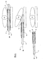
- the sheaths 13 are sufficiently long to ensure that nearly the entire of each respective tongue 3 can be covered by the sheath 13 in the doubled back arrangement described above. However, in the initial configuration, the sheaths 13 do not cover substantially all of their respective tongues 3 and a first portion of the support surface is covered by the sheath 13 while the remainder thereof is not covered. Excess sheath material is contained within the hollow cavity 11 of the tongue 3 (where this excess material has been drawn in through the holes in the free ends of the tongues 3). This first configuration can be seen in Figure 2 .
- Each sheath 13 has a cross-sectioned width of a size which is suitable to allow the sheath 13 to be slid onto a tongue 3.
- the sheaths 13 are of a suitable size to allow the sheaths 13 to be tightly fitted to the tongues 3.
- Each sheath 13 and tongue 3 form a respective lifting element attached to the arm 2.
- the arm 2 also has a hollow cavity (not shown) running along the length thereof which is in fluid communication the hollow cavity 11 in each of the tongues 3 attached thereto.
- motors (not shown) for each respective tongue 3 may be located within the hollow cavity of the arm 2.
- the motors are operable to drive spools (not shown) associated with each of the tongues 3.
- the spools each operate a drawstring 15, one end of which is secured to the spool and the other end of which is attached to a portion of the respective sheath 13 - preferably at the tip of the sheath 13.
- a plunger (not shown) is located with the hollow cavity 11 of each tongue 3.
- One end of a drawstring 15 is attached to the plunger and the other end is attached to the sheath 13.
- the plunger does not have a tight fit in the hollow cavity 11 of the tongue 3 and, thus, allows air to pass around it and into the sheath 13.
- one or more holes may be formed through the plunger to allow air to pass therethrough.
- the hollow cavity of the arm 2 is connected to a compressor 16 which is operable to force air (or another fluid, which may be a liquid) into the hollow cavity of the arm and into the hollow cavities of the tongues 3 connected thereto.
- air or another fluid, which may be a liquid
- the sheath 13 on each of the tongues 3 may be inflated.
- the compressor 16 may force air (or another fluid) out of the arm 2 and, consequently, out of the tongues (or a release valve may be opened to allow the air in the sheath 13 to be released to, for example, the atmosphere or an air reservoir) - thus, deflating the sheaths 13.
- the compressor 16 is preferably attached to the trolley 10 and could, for example be mounted on or next to the tower 8.
- the arm 2 does not have a hollow cavity and the compressor is connected directly to the tongues 3 through one or more pipes.
- the sheaths 13 should be made out of a material which is substantially airtight.
- the sheaths could comprise multiple layers including an airtight (or substantially airtight) inner layer, and an outer layer.
- the outer layer comprises a number of sublayers; for example, an innermost sublayer could be a durable layer designed to prevent damage to the inner layer, the next innermost sublayer could comprise a removable layer which can be sterilised between uses or could be disposable.
- the sheaths 13 should be constructed out of a flexible material or materials.
- the sheaths 13 could, for example, be constructed out of a rubber-like material.
- the sheaths 13 are constructed out of polyurethane coated nylon.
- the trolley 10 also includes an arrangement (not shown) suitable to adjust the angle of the tongues 3 with respect to the horizontal (the tongues 3 preferably normally being substantially horizontal).
- This angle adjustment arrangement preferably comprises one or more hydraulic jacks.
- the angle adjustment arrangement may comprise a separate arrangement for each tongue 3 so that they can be operated independently.
- the angle adjustment arrangement could comprise an arrangement for two or more tongues 3 so that they can be operated in groups.
- the angle adjustment arrangement could comprise a single arrangement for all the tongues 3 so that they can be operated in unison. Of course, even if there is not a single arrangement for all of the tongues 3, the arrangements may still be operated in unison or substantially in unison.
- the angle adjustment arrangement may control the orientation of the tongues 3 with respect to the arm 2, or the arm 2 with respect to the base 4.
- Embodiments of the present invention which include an angle adjustment arrangement are advantageous in situations in which the object (or patient 21) which is to be lifted is partially recessed into the surface from which it is to be lifted - for example, a patient on a soft mattress. Under these circumstances the angle adjustment arrangement can be utilised to adjust the angle of the tongues 3 from the horizontal to allow the sheaths 13 to inflate into mattress and under the patient 21. Once the patient 21 has been lifted, the tongues 3 may be returned to a substantially horizontal angle.
- the arm 2 includes a number of sections attached to the neighbouring sections by hinges (not shown).
- the arm 2 has two hinges and, thus, three sections.
- the sections generally comprising a leg support section, a seat section and a back support section.
- the hinges may be activated hydraulically or electrically.
- the sections of the arm 2 may be moved with respect to each other from a first to a second configuration in order to adjust the arrangement of the patient 21 - for example from a lying to a sitting arrangement. Consequently, a patient can be transferred from a bed to, for example, a chair or wheel chair.
- tongues 3 mounted on a plurality of separate arms 2 the orientations or positions of which may be controlled - for example, the trolley 10 could *include three arms 2 each with one or more respective tongues 3.
- hinges could be replaced by any other type of similar joint. These joints could allow different degrees of movement in multiple axes. Indeed, it is envisaged that the tongues 3 may be also be rotated with respect to each other.
- Figure 3 shows a first method of lifting a patient in accordance with an embodiment of the present invention, in which the sheath 13 on each tongue 3 is attached thereto at a fixed location.
- the transfer trolley 10 is manoeuvred such that the arm 2 is generally parallel to a bed 20 on which a patient 21 is located (of course, the bed 20 could equally be manoeuvred such that it is generally parallel to the arm 2 of the transfer trolley).
- the height of the arm may be adjusted using the telescopically mounted turret 9 such that lower surfaces of the tongues 3 are generally level with an upper surface of the bed 20.
- the sheaths 13 and tongues 3 are in the initial configuration, shown in Figure 3a .
- the sheaths 13 are inflated by pumping air or another fluid into the figures 3 using the compressor.
- the sheaths 13 are inflated the portions of the sheaths that are contained within the tongues 3 move out of the hollow cavities 11 of the tongues 3.
- the sheaths 13 unfurl and are inflated, in a direction which is generally parallel to the tongues 3, and insinuate themselves under the patient 21.
- the double backed arrangement of the sheaths 13 on the tongues 3 may decrease in length of extension along the tongues 3 as the fold moves closer to the securing mechanism 14.
- sheaths 13 Once the sheaths 13 are in position under the patient 21 they can be fully inflated, thus lifting the patient 21 off the bed 20. If drawstrings 15 are utilised in the transfer trolley (as discussed above), then the spools and motors (or plungers) must allow the drawstrings 15 to be deployed so that the sheaths 13 can inflate. The sheaths 13 and tongues are now in a second configuration, shown in Figure 3b .
- the sheaths 13 unfurl and evert under the patient 21 as they inflate. If operated correctly there is a little or no sliding of the sheaths 13 under the patient 21, which could damage open wounds (such are burns) or could drag bed linen across the bed 20 as the sheaths 13 inflate. Instead, the sheaths 13 insinuate under the patient 21.
- the patient 21 is, in the second configuration of the trolley 10, supported on the inflated sheaths 13 which are, in turn, supported by the bed 20.
- the tongues 3 are then moved into the inflated sheaths 13 (see Figure 3c ). It will be appreciated that during this operation the tongues 3 will displace some of the air contained with in the sheaths 13.
- the compressor therefore, includes a valve arrangement (not shown) to allow this air to escape without significantly decreasing the fluid pressure within the sheaths 13 (which should remain inflated until the tongues 3 are moved into a position such that they can support the weight of the patient 21).
- the valve may not be present and the fluid pressure in the sheaths 13 is simply allowed to increase.
- the sheaths 13 may be deflated (although, it will be appreciated that this is not necessary).
- the tongues 3 and sheaths 13 are now in a third configuration shown in Figure 3c , and it will be appreciated that a second portion of the support surface of each tongue 3, which was not covered by the sheath 13 in the initial configuration is now covered thereby.
- the tongues 3 can be moved into the sheaths 13 in a number of different manners; for example, the transfer trolley 10 can be moved towards the bed or, if the transfer trolley has a tower 8 mounted on a track (as described above), then the tower 8 can be driven along the track such that the tower 8, turret 9, arm 2 and tongues 3 all move towards the bed 20 but the base 4 remains in a substantially fixed location with respect to the bed 20.
- the operation of the transfer trolley 10, arm 2, and tongues 3, is generally similar to the first method described above, and at first the trolley 10 is in an identical initial configuration, shown in Figure 4a .
- the sheaths 13 are inflated the tongues 3 are contemporaneously moved towards the patient into the inflating cylinders formed by the sheaths 13 (see Figure 4b ).
- the sheaths 13 inflate and unfurl under the patient 21.
- the sheaths 13 inflate the tongues 3 are moved into the now inflated parts of the sheaths 13; it is not necessary to wait for the patient 21 to be entirely supported on the fully inflated sheaths 13 before the tongues 3 are manoeuvred into the partially inflated sheaths 13.
- the second configuration (as described above) is never reached. Instead, the movements necessary to achieve the third configuration are begun as the sheaths 13 inflate and the trolley 10 is placed in the third configuration without the intervening second configuration.
- the principle of operation of the second method is substantially similar to the first method; however, in some instances the second method can be utilised to lift a patient 21 from their bed 20 (see Figure 4c ) in less time than would be possible by simply using the first method.
- a third method of collecting a patient 21 according to an embodiment of the present invention is shown in Figure 5 .
- the third method requires sliding seals 18 to be used to attach the open ends of the sheaths 13 to the outer surfaces of the tongues 3 (as described above).
- the sheaths 13 are inflated in the same manner as described above in relation to the first method.
- the sliding seals are slid along the tongues 3 towards the arm 2.
- the tongues 3 are moved into the inflating sheaths 13 towards the patient 21 (see Figure 4b ).
- the third method can be utilised to lift a patient 21 from a bed 20 in less time than is possible using the first or second methods.
- sheaths 13 may be fully insinuated under the patient 21 before the sliding seals 18 are slid towards the arm 2, and that it is not necessary to slide the seals 18 towards the arm before this.
- the trolley 10 is arranged in the initial configuration (as described above) and the third configuration is achieved not only by inflating the sheaths 13 and moving the tongues 3 towards the patient (into the inflated sheaths 13) but the sheaths 13 are also effectively drawn down the length of the tongues 3 by the sliding seals 18.
- the seals 18 are generally held in place with respect to the sheaths 13 by abutment against the patient's bed 20.
- the first two methods of collecting a patient 21 require the sheaths 13 to be insinuated beneath the patient 21.
- the tongues 3 are then moved relative to the sheaths 13 such that the sheaths 13 roll back on their respective tongues 3 to cover a previously uncovered part thereof.
- the "rolling back" is not required because the sliding seal 18 moves along the tongue 3 towards the arm 2.
- a first method for offloading a patient from the transfer trolley 10 onto a bed 20 is shown in figure 6 .
- the transfer trolley 10 begins the offloading process in a configuration which is generally identical to the third configuration described above in relation to the patient collecting process.
- the patient is supported on the tongues 3 of the transfer trolley 10 and the sheaths 13 remain inflated with the tongues 3 located within the sheaths 13.
- the transfer trolley is manoeuvred with respect to a bed 20 such that lower surfaces of the tongues 3 are positioned above and adjacent to the upper surface of the bed 20.
- the drawstrings 15 are utilised to draw a portion of the sheaths 13 into the hollow cavities 11 of their respective tongues 3.
- the sheaths 13 are sufficiently inflated to ensure that as the portion of the sheaths 13 are drawn into the tongues 3, inflated portions of the sheaths 13 form cylinders (see Figure 6b ).
- each respective sheath 13 As a portion of each respective sheath 13 is drawn into its tongue 3, the tongues 3 are retracted from beneath the patient. Thus, the patient is at least partially supported by the cylinders formed by the inflated sheaths 13. The portion of each sheath 13 which is drawn into its respective tongue 3 is increased such that the inflated cylinders of the sheaths 13 decrease in size. Thus, the patient 21 is gently lowered onto the bed 20 by the sheath 13 as it rolls into the tongue 3.
- the tongues 3 can be moved away from the bed 20 in a number of different manners; for example, the transfer trolley 10 can be moved away from the bed or, if the transfer trolley has a tower 8 mounted on a track (as described above), then the tower 8 can be driven along the track such that the tower 8, turret 9, arm 2 and tongues 3 all move away from the bed 20 but the base 4 remains in a substantially fixed location with respect to the bed 20.
- the transfer trolley 10 is in a third offloading configuration which is generally identical to the initial configuration described above in relation to the collection of a patient.
- a second method of offloading a patient in accordance with an embodiment of the present invention is shown in figure 7 .
- the second method utilises an embodiment of the transfer trolley 10 of the present invention which includes sliding seals 18.
- the method begins with a patient located on the transfer trolley 10 in a first offloading configuration which is substantially identical to the third collecting configuration described above in relation to the third collecting method.
- a drawstring 15 is attached to each of the sheaths 13.
- a portion of each sheath 13 is drawn into its respective tongue 3 by the drawstring 15.
- the sliding seal 18 (which is not present in the embodiment of the transfer trolley 10 utilised in the first method) on each tongue 3 is moved from a position which is close to the proximal end of the tongue 3 towards the distal end thereof. Movement of the sliding seals 18 may be achieved by movement of the tongues 3 with respect to, for example, to a bed 20 on which a patient 21 is located - the seals 18 being abutted against, and generally prevented from moving, by the bed 20.
- the sheaths 13 form cylinders (as drawstrings 15 draw the excess sheath material into the hollow cavities 11 of the tongues 3) which partially support the weight of the patient 21 as the patient 21 is lowered to the bed 20.
- the cylinder formed by the sheath 13 steadily decrease in size as the sheaths 13 are drawn back into their respective tongues 3.
- inventions of the present invention may utilise a computer (not shown), microcontroller (not shown) or other electronic circuitry (not shown) to control the operation of the transfer trolley 10, including the wheels or casters 17, any track, any valves associated with the trolley 10, and the mechanism utilised to raise and lower the turret 9.
- a computer not shown
- microcontroller not shown
- other electronic circuitry not shown
Landscapes
- Health & Medical Sciences (AREA)
- Nursing (AREA)
- Life Sciences & Earth Sciences (AREA)
- Animal Behavior & Ethology (AREA)
- General Health & Medical Sciences (AREA)
- Public Health (AREA)
- Veterinary Medicine (AREA)
- Invalid Beds And Related Equipment (AREA)
- Chain Conveyers (AREA)
Claims (15)
- L'invention concerne un élément de levage destiné à être utilisé avec un chariot de transfert (10), ledit élément comprenant : un organe de supports (3) ayant une surface de support, une cavité creuse (11) sur la longueur de l'organe de support (3) et une gaine (13) fixée à l'organe de support (3) de sorte que, dans une configuration initiale, une première partie de la surface de support est recouverte par la gaine (13) et une deuxième partie de la surface de support est découverte, et dans laquelle la cavité creuse (11) est conçue de façon à recevoir la partie en excès de la gaine (13), la gaine (13) est conçue pour être gonflée de façon à s'étendre et se retourner, et à s'insérer sous une charge afin de supporter ladite charge, et, après gonflage, l'organe de support (3) et la gaine (13) peuvent être déplacés l'un par rapport à l'autre de sorte que l'organe de support (3) puisse s'étendre plus loin dans la gaine (13), que la partie en excès de la gaine (13) sorte de la cavité (11), que la seconde partie de la surface de support soit recouverte par la gaine (13) et que la surface de support supporte au moins partiellement la charge.
- Un élément de levage selon la revendication 1, dans lequel:la gaine (13) est fixée à une section principale du corps de l'organe de support (3), oula gaine (13) est fixée à la section principale du corps au moyen d'un système de joint coulissant (18).
- Un élément de levage selon la revendication 1, dans lequel
la gaine (13) est fixée à une section principale du corps de l'organe de support (3) ; l'organe de support (3) a une extrémité distale et une extrémité proximale ;
la gaine (13) est fixée à l'organe de support (3) à un point de fixation éloigné de l'extrémité proximale de l'organe de support ; après le gonflage, l'élément de support (3) et le manchon (13) peuvent être déplacés l'un par rapport à l'autre de sorte qu'une partie du manchon (13) recouvre au moins une partie de la région de la surface d'appui entre le point de fixation et l'extrémité proximale de l'organe de support (3). - Un élément de levage selon la revendication 1, dans lequel :la gaine (13) est fixée à une section principale du corps (3) au moyen un système de joint coulissant (18) ;l'organe de support (3) a une extrémité distale et un extrémité proximale ; la gaine (13) est fixée à l'organe de support (3) par le système de joint coulissant (18) prévu entre les extrémités proximale et distale et pour glisser le long d'au moins une partie de la longueur de l'organe de support (13) ; et après le gonflage, le joint coulissant peut glisser vers l'extrémité proximale de l'organe de support pour que la charge puisse être au moins partiellement supportée par l'organe de support (3).
- Un élément de levage selon l'une quelconque des revendications précédentes, comprenant en outre :un canal de liquide pour gonfler la gaine (13) ; ou un canal de liquide pour gonfler la gaine (13) dans lequel ledit canal de liquide est prévu à l'intérieur de l'organe de support (3).
- Un élément de levage selon l'une quelconque des revendications précédentes, comprenant en outre un cordon (15) fixé à la gaine (13) et permettant de commander un aspect du gonflage ou du dégonflage de la gaine (13),
- Un chariot de transfert (10), y compris un ou plusieurs éléments de levage selon l'une quelconque des revendications précédentes.
- Un chariot de transfert (10) selon la revendication 7, dans lequel les éléments de levage sont espacés de manière à constituer un arrangement sur lequel un patient peut être placé.
- Un chariot de transfert (10) selon la revendication 7 ou 8, comprenant en outre :un dispositif pour commander sélectivement l'un ou plusieurs éléments de levage, ou un dispositif de base (5, 6, 6), y compris une piste : et une tour (8) montée sur la piste utilisable pour soutenir un ou plusieurs éléments de levage, dans lequel un ou plusieurs éléments de levage peut être déplacé par rapport à la base (5, 6, 7) en déplaçant la tour (8) sur la piste.
- Un chariot de transfert (10) selon l'une quelconque des revendications 7 à 9, dans lequel les éléments de levage sont supportés par un ou plusieurs bras (2).
- Un chariot de transfert (10) selon la revendication 10, dans lequel : les éléments de levage sont supportés par une pluralité de bras (2), ou les éléments de levage sont supportés par une pluralité de bras (2) et deux ou plusieurs bras de ladite pluralité de bras (2) sont reliés entre eux par des joints.
- Un chariot de transfert selon la revendication 11, dans lequel les bras peuvent être déplacés les uns par rapport aux autres.
- Un chariot de transfert (10) selon l'une quelconque des revendications 7 à 12 comprenant en outre un dispositif de réglage d'angle permettant de régler l'angle des éléments de levage par rapport à un plan horizontal.
- Un chariot de transfert (10) selon l'une quelconque des revendications 7 à 13 dans lequel les éléments de levage peuvent être tournés les uns par rapport aux autres.
- Un procédé de levage de charge au moyen d'un élément de levage doté d'une gaine (13) et d'un organe de support (3) selon l'une quelconque des revendications 1 à 6 comprenant les étapes suivantes : gonflage de la gaine (13) permettant du ladite gaine (13) de se glisser sous la charge, et déplacement de la gaine (13) et de l'organe de support l'un par rapport à l'autre de manière que l'organe de support (3) s'étende dans la gaine (13), la partie en excès de la gaine (13) sorte de la cavité creuse (11) et l'organe de support (3) supporte au moins partiellement la charge.
Applications Claiming Priority (2)
| Application Number | Priority Date | Filing Date | Title |
|---|---|---|---|
| GBGB0625097.1A GB0625097D0 (en) | 2006-12-15 | 2006-12-15 | A transfer trolley |
| PCT/GB2007/004741 WO2008071940A1 (fr) | 2006-12-15 | 2007-12-11 | Chariot de transfert |
Publications (2)
| Publication Number | Publication Date |
|---|---|
| EP2101705A1 EP2101705A1 (fr) | 2009-09-23 |
| EP2101705B1 true EP2101705B1 (fr) | 2011-05-25 |
Family
ID=37712244
Family Applications (1)
| Application Number | Title | Priority Date | Filing Date |
|---|---|---|---|
| EP07848486A Not-in-force EP2101705B1 (fr) | 2006-12-15 | 2007-12-11 | Chariot de transfert |
Country Status (8)
| Country | Link |
|---|---|
| US (1) | US8307474B2 (fr) |
| EP (1) | EP2101705B1 (fr) |
| CN (1) | CN101626748A (fr) |
| AT (1) | ATE510526T1 (fr) |
| AU (1) | AU2007331329A1 (fr) |
| CA (1) | CA2672060A1 (fr) |
| GB (1) | GB0625097D0 (fr) |
| WO (1) | WO2008071940A1 (fr) |
Families Citing this family (10)
| Publication number | Priority date | Publication date | Assignee | Title |
|---|---|---|---|---|
| GB2473046A (en) * | 2009-08-28 | 2011-03-02 | Personal Lifting Ltd | A support element for a transfer trolley with a removable cover |
| GB2473047A (en) * | 2009-08-28 | 2011-03-02 | Personal Lifting Ltd | A inflatable support element for a transfer trolley with a tether to allow rotation |
| GB2473045A (en) * | 2009-08-28 | 2011-03-02 | Personal Lifting Ltd | A support element for a transfer trolley with a narrowed end |
| KR101402656B1 (ko) | 2011-12-27 | 2014-06-11 | 한국과학기술원 | 척추환자 이송장치 |
| US9107785B2 (en) | 2013-05-24 | 2015-08-18 | Robert Ferrin | Gurney attachment for use in helicopter transport and method therefor |
| GB2536910B (en) * | 2015-03-30 | 2017-07-05 | Ironmonger Paul | A domestic appliance lifting device/trolley |
| US20180353361A1 (en) * | 2015-11-24 | 2018-12-13 | Lateral Prep, LLC | Supine patient transfer package |
| JP7266309B2 (ja) * | 2017-09-27 | 2023-04-28 | シガ イノベーションズ, インコーポレイテッド | 空気支承式患者移転システム |
| CN112426308A (zh) * | 2020-11-23 | 2021-03-02 | 彭向阳 | 一种医疗用瘫痪人员承托转运设备 |
| WO2025183727A1 (fr) * | 2024-02-26 | 2025-09-04 | Massachusetts Institute Of Technology | Structures gonflables souples réversibles pour aider des sujets |
Family Cites Families (18)
| Publication number | Priority date | Publication date | Assignee | Title |
|---|---|---|---|---|
| US1857031A (en) * | 1929-08-02 | 1932-05-03 | Schaffer Edward | Combined hoist and conveyer |
| US3178732A (en) | 1962-03-27 | 1965-04-20 | George R Stibitz | Eversible lifting device |
| FR91361E (fr) * | 1966-03-25 | 1968-05-31 | Detec Sa | Appareil pour le traitement des brûlures |
| GB1270150A (en) * | 1969-09-23 | 1972-04-12 | Duncan Islay Campbell | Improvements in and relating to trolleys for carrying stretchers |
| US3757788A (en) | 1972-02-28 | 1973-09-11 | Renfroe H | Prying and/or frictionless probing device |
| SE387236B (sv) | 1974-04-01 | 1976-09-06 | B E Ilon | Skyddsanordning vid lyftkuddar |
| GB8925950D0 (en) | 1989-11-16 | 1990-01-04 | Fulmer Systems Ltd | Improvements in or relating to a transfer trolley |
| FR2678511A1 (fr) * | 1991-07-05 | 1993-01-08 | Ciposa Microtech | Dispositif d'assistance pour la manipulation de malades grabataires. |
| NL9101806A (nl) | 1991-10-28 | 1993-05-17 | Endomed | Inrichting voor het van een ondergrond oplichten van een lichaam. |
| WO1994027548A1 (fr) | 1993-06-02 | 1994-12-08 | Bano Anton Carlos | Ameliorations apportees a des lits d'usage clinique |
| ES2117909B1 (es) | 1993-06-02 | 1999-04-01 | Bano Anton Carlos | Mejoras introducidas en la patente de invencion n- p-9301212/8, por: perfeccionamientos introducidos en camas y sillones terapeuticos. |
| GB0318675D0 (en) | 2003-08-08 | 2003-09-10 | Mangar Int Ltd | Control unit for inflatable devices |
| ATE418951T1 (de) * | 2005-08-01 | 2009-01-15 | Ergo Asyst Technology Llc | Patientenüberführungssystem |
| AU2006302675B2 (en) | 2005-10-07 | 2012-05-24 | Conmedisys, Inc. | Patient lift and transfer device |
| CA2626137C (fr) | 2005-10-25 | 2015-01-13 | Lysekilen Ab | Coussin de levage cuneiforme |
| SE529429C2 (sv) | 2005-10-25 | 2007-08-07 | Maxgrepp Teknik Ab | Kilformad lyftkudde |
| US20070295339A1 (en) | 2006-06-27 | 2007-12-27 | Osamu Mizuno | Loading/unloading unit and a transfer apparatus |
| US7818831B2 (en) * | 2006-08-14 | 2010-10-26 | Mohammad Hassan Mahdjoubi | Multi-purpose hospital bed |
-
2006
- 2006-12-15 GB GBGB0625097.1A patent/GB0625097D0/en not_active Ceased
-
2007
- 2007-12-11 AT AT07848486T patent/ATE510526T1/de not_active IP Right Cessation
- 2007-12-11 US US12/519,125 patent/US8307474B2/en not_active Expired - Fee Related
- 2007-12-11 EP EP07848486A patent/EP2101705B1/fr not_active Not-in-force
- 2007-12-11 CN CN200780046088A patent/CN101626748A/zh active Pending
- 2007-12-11 WO PCT/GB2007/004741 patent/WO2008071940A1/fr not_active Ceased
- 2007-12-11 CA CA002672060A patent/CA2672060A1/fr not_active Abandoned
- 2007-12-11 AU AU2007331329A patent/AU2007331329A1/en not_active Abandoned
Also Published As
| Publication number | Publication date |
|---|---|
| US8307474B2 (en) | 2012-11-13 |
| CA2672060A1 (fr) | 2008-06-19 |
| CN101626748A (zh) | 2010-01-13 |
| EP2101705A1 (fr) | 2009-09-23 |
| WO2008071940A1 (fr) | 2008-06-19 |
| US20100138989A1 (en) | 2010-06-10 |
| AU2007331329A1 (en) | 2008-06-19 |
| ATE510526T1 (de) | 2011-06-15 |
| GB0625097D0 (en) | 2007-01-24 |
Similar Documents
| Publication | Publication Date | Title |
|---|---|---|
| EP2101705B1 (fr) | Chariot de transfert | |
| US8793824B2 (en) | Tilt bed | |
| JP3686113B2 (ja) | 医療用ベッド及び患者移送方法 | |
| US12377006B2 (en) | Systems and methods for lifting and positioning a patient | |
| US6662388B2 (en) | Patient adjustment device | |
| EP2462912B1 (fr) | Augmentation de la vessie de matelas pendant la sortie de chaise | |
| US20220023121A1 (en) | Method of positioning a patient | |
| US7752687B1 (en) | Patient transfer device | |
| EP2436352A2 (fr) | Section d'étage à alimentation pneumatique | |
| AU2020225482B2 (en) | Devices and systems for moving a person on a support apparatus | |
| JP7117589B2 (ja) | 昇降装置および片持ち支持された支持台を備える昇降システム | |
| US20190216663A1 (en) | Patient handling apparatus and method of use | |
| CN111216140B (zh) | 托抱式多臂协作转运护理机器人 | |
| WO2025137569A1 (fr) | Systèmes de transfert avec robots de retournement souple et procédés associés | |
| US12520948B2 (en) | Expandable bed | |
| US20230381041A1 (en) | Methods and devices for repositioning a patient on a support apparatus | |
| GB2473047A (en) | A inflatable support element for a transfer trolley with a tether to allow rotation | |
| CA2138887A1 (fr) | Dispositif de soulevement des alites | |
| JP2005192813A (ja) | 走行式可動リフトを有するストレッチャー | |
| GB2473045A (en) | A support element for a transfer trolley with a narrowed end |
Legal Events
| Date | Code | Title | Description |
|---|---|---|---|
| PUAI | Public reference made under article 153(3) epc to a published international application that has entered the european phase |
Free format text: ORIGINAL CODE: 0009012 |
|
| 17P | Request for examination filed |
Effective date: 20090709 |
|
| AK | Designated contracting states |
Kind code of ref document: A1 Designated state(s): AT BE BG CH CY CZ DE DK EE ES FI FR GB GR HU IE IS IT LI LT LU LV MC MT NL PL PT RO SE SI SK TR |
|
| DAX | Request for extension of the european patent (deleted) | ||
| 17Q | First examination report despatched |
Effective date: 20100301 |
|
| GRAP | Despatch of communication of intention to grant a patent |
Free format text: ORIGINAL CODE: EPIDOSNIGR1 |
|
| GRAS | Grant fee paid |
Free format text: ORIGINAL CODE: EPIDOSNIGR3 |
|
| GRAA | (expected) grant |
Free format text: ORIGINAL CODE: 0009210 |
|
| AK | Designated contracting states |
Kind code of ref document: B1 Designated state(s): AT BE BG CH CY CZ DE DK EE ES FI FR GB GR HU IE IS IT LI LT LU LV MC MT NL PL PT RO SE SI SK TR |
|
| REG | Reference to a national code |
Ref country code: GB Ref legal event code: FG4D |
|
| REG | Reference to a national code |
Ref country code: CH Ref legal event code: EP |
|
| REG | Reference to a national code |
Ref country code: IE Ref legal event code: FG4D |
|
| REG | Reference to a national code |
Ref country code: DE Ref legal event code: R096 Ref document number: 602007014898 Country of ref document: DE Effective date: 20110707 |
|
| REG | Reference to a national code |
Ref country code: NL Ref legal event code: VDEP Effective date: 20110525 |
|
| PG25 | Lapsed in a contracting state [announced via postgrant information from national office to epo] |
Ref country code: SE Free format text: LAPSE BECAUSE OF FAILURE TO SUBMIT A TRANSLATION OF THE DESCRIPTION OR TO PAY THE FEE WITHIN THE PRESCRIBED TIME-LIMIT Effective date: 20110525 Ref country code: PT Free format text: LAPSE BECAUSE OF FAILURE TO SUBMIT A TRANSLATION OF THE DESCRIPTION OR TO PAY THE FEE WITHIN THE PRESCRIBED TIME-LIMIT Effective date: 20110926 Ref country code: LT Free format text: LAPSE BECAUSE OF FAILURE TO SUBMIT A TRANSLATION OF THE DESCRIPTION OR TO PAY THE FEE WITHIN THE PRESCRIBED TIME-LIMIT Effective date: 20110525 |
|
| PG25 | Lapsed in a contracting state [announced via postgrant information from national office to epo] |
Ref country code: SI Free format text: LAPSE BECAUSE OF FAILURE TO SUBMIT A TRANSLATION OF THE DESCRIPTION OR TO PAY THE FEE WITHIN THE PRESCRIBED TIME-LIMIT Effective date: 20110525 Ref country code: ES Free format text: LAPSE BECAUSE OF FAILURE TO SUBMIT A TRANSLATION OF THE DESCRIPTION OR TO PAY THE FEE WITHIN THE PRESCRIBED TIME-LIMIT Effective date: 20110905 Ref country code: FI Free format text: LAPSE BECAUSE OF FAILURE TO SUBMIT A TRANSLATION OF THE DESCRIPTION OR TO PAY THE FEE WITHIN THE PRESCRIBED TIME-LIMIT Effective date: 20110525 Ref country code: IS Free format text: LAPSE BECAUSE OF FAILURE TO SUBMIT A TRANSLATION OF THE DESCRIPTION OR TO PAY THE FEE WITHIN THE PRESCRIBED TIME-LIMIT Effective date: 20110925 Ref country code: GR Free format text: LAPSE BECAUSE OF FAILURE TO SUBMIT A TRANSLATION OF THE DESCRIPTION OR TO PAY THE FEE WITHIN THE PRESCRIBED TIME-LIMIT Effective date: 20110826 Ref country code: BE Free format text: LAPSE BECAUSE OF FAILURE TO SUBMIT A TRANSLATION OF THE DESCRIPTION OR TO PAY THE FEE WITHIN THE PRESCRIBED TIME-LIMIT Effective date: 20110525 Ref country code: AT Free format text: LAPSE BECAUSE OF FAILURE TO SUBMIT A TRANSLATION OF THE DESCRIPTION OR TO PAY THE FEE WITHIN THE PRESCRIBED TIME-LIMIT Effective date: 20110525 Ref country code: CY Free format text: LAPSE BECAUSE OF FAILURE TO SUBMIT A TRANSLATION OF THE DESCRIPTION OR TO PAY THE FEE WITHIN THE PRESCRIBED TIME-LIMIT Effective date: 20110525 Ref country code: LV Free format text: LAPSE BECAUSE OF FAILURE TO SUBMIT A TRANSLATION OF THE DESCRIPTION OR TO PAY THE FEE WITHIN THE PRESCRIBED TIME-LIMIT Effective date: 20110525 |
|
| PG25 | Lapsed in a contracting state [announced via postgrant information from national office to epo] |
Ref country code: NL Free format text: LAPSE BECAUSE OF FAILURE TO SUBMIT A TRANSLATION OF THE DESCRIPTION OR TO PAY THE FEE WITHIN THE PRESCRIBED TIME-LIMIT Effective date: 20110525 |
|
| PG25 | Lapsed in a contracting state [announced via postgrant information from national office to epo] |
Ref country code: EE Free format text: LAPSE BECAUSE OF FAILURE TO SUBMIT A TRANSLATION OF THE DESCRIPTION OR TO PAY THE FEE WITHIN THE PRESCRIBED TIME-LIMIT Effective date: 20110525 Ref country code: CZ Free format text: LAPSE BECAUSE OF FAILURE TO SUBMIT A TRANSLATION OF THE DESCRIPTION OR TO PAY THE FEE WITHIN THE PRESCRIBED TIME-LIMIT Effective date: 20110525 |
|
| PG25 | Lapsed in a contracting state [announced via postgrant information from national office to epo] |
Ref country code: DK Free format text: LAPSE BECAUSE OF FAILURE TO SUBMIT A TRANSLATION OF THE DESCRIPTION OR TO PAY THE FEE WITHIN THE PRESCRIBED TIME-LIMIT Effective date: 20110525 Ref country code: SK Free format text: LAPSE BECAUSE OF FAILURE TO SUBMIT A TRANSLATION OF THE DESCRIPTION OR TO PAY THE FEE WITHIN THE PRESCRIBED TIME-LIMIT Effective date: 20110525 Ref country code: RO Free format text: LAPSE BECAUSE OF FAILURE TO SUBMIT A TRANSLATION OF THE DESCRIPTION OR TO PAY THE FEE WITHIN THE PRESCRIBED TIME-LIMIT Effective date: 20110525 Ref country code: PL Free format text: LAPSE BECAUSE OF FAILURE TO SUBMIT A TRANSLATION OF THE DESCRIPTION OR TO PAY THE FEE WITHIN THE PRESCRIBED TIME-LIMIT Effective date: 20110525 |
|
| PLBE | No opposition filed within time limit |
Free format text: ORIGINAL CODE: 0009261 |
|
| STAA | Information on the status of an ep patent application or granted ep patent |
Free format text: STATUS: NO OPPOSITION FILED WITHIN TIME LIMIT |
|
| 26N | No opposition filed |
Effective date: 20120228 |
|
| PG25 | Lapsed in a contracting state [announced via postgrant information from national office to epo] |
Ref country code: IT Free format text: LAPSE BECAUSE OF FAILURE TO SUBMIT A TRANSLATION OF THE DESCRIPTION OR TO PAY THE FEE WITHIN THE PRESCRIBED TIME-LIMIT Effective date: 20110525 |
|
| REG | Reference to a national code |
Ref country code: DE Ref legal event code: R097 Ref document number: 602007014898 Country of ref document: DE Effective date: 20120228 |
|
| PG25 | Lapsed in a contracting state [announced via postgrant information from national office to epo] |
Ref country code: MC Free format text: LAPSE BECAUSE OF NON-PAYMENT OF DUE FEES Effective date: 20111231 |
|
| REG | Reference to a national code |
Ref country code: CH Ref legal event code: PL |
|
| REG | Reference to a national code |
Ref country code: IE Ref legal event code: MM4A |
|
| PG25 | Lapsed in a contracting state [announced via postgrant information from national office to epo] |
Ref country code: LI Free format text: LAPSE BECAUSE OF NON-PAYMENT OF DUE FEES Effective date: 20111231 Ref country code: CH Free format text: LAPSE BECAUSE OF NON-PAYMENT OF DUE FEES Effective date: 20111231 Ref country code: IE Free format text: LAPSE BECAUSE OF NON-PAYMENT OF DUE FEES Effective date: 20111211 |
|
| PG25 | Lapsed in a contracting state [announced via postgrant information from national office to epo] |
Ref country code: MT Free format text: LAPSE BECAUSE OF FAILURE TO SUBMIT A TRANSLATION OF THE DESCRIPTION OR TO PAY THE FEE WITHIN THE PRESCRIBED TIME-LIMIT Effective date: 20110525 |
|
| PG25 | Lapsed in a contracting state [announced via postgrant information from national office to epo] |
Ref country code: LU Free format text: LAPSE BECAUSE OF NON-PAYMENT OF DUE FEES Effective date: 20111211 |
|
| PG25 | Lapsed in a contracting state [announced via postgrant information from national office to epo] |
Ref country code: BG Free format text: LAPSE BECAUSE OF FAILURE TO SUBMIT A TRANSLATION OF THE DESCRIPTION OR TO PAY THE FEE WITHIN THE PRESCRIBED TIME-LIMIT Effective date: 20110825 |
|
| PG25 | Lapsed in a contracting state [announced via postgrant information from national office to epo] |
Ref country code: TR Free format text: LAPSE BECAUSE OF FAILURE TO SUBMIT A TRANSLATION OF THE DESCRIPTION OR TO PAY THE FEE WITHIN THE PRESCRIBED TIME-LIMIT Effective date: 20110525 |
|
| PG25 | Lapsed in a contracting state [announced via postgrant information from national office to epo] |
Ref country code: HU Free format text: LAPSE BECAUSE OF FAILURE TO SUBMIT A TRANSLATION OF THE DESCRIPTION OR TO PAY THE FEE WITHIN THE PRESCRIBED TIME-LIMIT Effective date: 20110525 |
|
| REG | Reference to a national code |
Ref country code: FR Ref legal event code: PLFP Year of fee payment: 9 |
|
| PGFP | Annual fee paid to national office [announced via postgrant information from national office to epo] |
Ref country code: GB Payment date: 20151209 Year of fee payment: 9 Ref country code: DE Payment date: 20151208 Year of fee payment: 9 |
|
| PGFP | Annual fee paid to national office [announced via postgrant information from national office to epo] |
Ref country code: FR Payment date: 20151208 Year of fee payment: 9 |
|
| REG | Reference to a national code |
Ref country code: DE Ref legal event code: R119 Ref document number: 602007014898 Country of ref document: DE |
|
| GBPC | Gb: european patent ceased through non-payment of renewal fee |
Effective date: 20161211 |
|
| REG | Reference to a national code |
Ref country code: FR Ref legal event code: ST Effective date: 20170831 |
|
| PG25 | Lapsed in a contracting state [announced via postgrant information from national office to epo] |
Ref country code: FR Free format text: LAPSE BECAUSE OF NON-PAYMENT OF DUE FEES Effective date: 20170102 |
|
| PG25 | Lapsed in a contracting state [announced via postgrant information from national office to epo] |
Ref country code: DE Free format text: LAPSE BECAUSE OF NON-PAYMENT OF DUE FEES Effective date: 20170701 Ref country code: GB Free format text: LAPSE BECAUSE OF NON-PAYMENT OF DUE FEES Effective date: 20161211 |