EP2102429B1 - Dachbodenleiteranordnung - Google Patents
Dachbodenleiteranordnung Download PDFInfo
- Publication number
- EP2102429B1 EP2102429B1 EP05733732A EP05733732A EP2102429B1 EP 2102429 B1 EP2102429 B1 EP 2102429B1 EP 05733732 A EP05733732 A EP 05733732A EP 05733732 A EP05733732 A EP 05733732A EP 2102429 B1 EP2102429 B1 EP 2102429B1
- Authority
- EP
- European Patent Office
- Prior art keywords
- ladder
- loft
- carriage
- assembly
- frame
- Prior art date
- Legal status (The legal status is an assumption and is not a legal conclusion. Google has not performed a legal analysis and makes no representation as to the accuracy of the status listed.)
- Expired - Lifetime
Links
Images


Classifications
-
- E—FIXED CONSTRUCTIONS
- E06—DOORS, WINDOWS, SHUTTERS, OR ROLLER BLINDS IN GENERAL; LADDERS
- E06C—LADDERS
- E06C1/00—Ladders in general
- E06C1/02—Ladders in general with rigid longitudinal member or members
- E06C1/04—Ladders for resting against objects, e.g. walls poles, trees
- E06C1/08—Ladders for resting against objects, e.g. walls poles, trees multi-part
- E06C1/12—Ladders for resting against objects, e.g. walls poles, trees multi-part extensible, e.g. telescopic
- E06C1/125—Ladders for resting against objects, e.g. walls poles, trees multi-part extensible, e.g. telescopic with tubular longitudinal members nested within each other
-
- E—FIXED CONSTRUCTIONS
- E04—BUILDING
- E04F—FINISHING WORK ON BUILDINGS, e.g. STAIRS, FLOORS
- E04F11/00—Stairways, ramps, or like structures; Balustrades; Handrails
- E04F11/02—Stairways; Layouts thereof
- E04F11/04—Movable stairways, e.g. of loft ladders which may or may not be concealable or extensible
- E04F11/06—Movable stairways, e.g. of loft ladders which may or may not be concealable or extensible collapsible, e.g. folding, telescopic
- E04F11/062—Movable stairways, e.g. of loft ladders which may or may not be concealable or extensible collapsible, e.g. folding, telescopic folding
Definitions
- the present invention relates to a loft ladder assembly according to the preamble of claim 1.
- Hatch doors are commonly provided in a ceiling to allow access to the loft or roof space of a building.
- Loft ladders are also known which are stored in the roof space and which are deployed by being pulled down after the hatch door has been opened.
- Conventional loft ladders are usually of the extendable type. This means that the ladder is formed of two (or sometimes three) ladder sections arranged in different planes, which can slide over one another and can be locked to each other in a stacked and in an extended position. Even after the sections have been stacked, they are longer than the hatch door. Consequently, to stow away the ladder, it first has to be raised into the loft and then pivoted for its lower end to be able to pass through the hatch.
- the stacked ladder is normally pivoted about an axis, which is near its centre so that the ladder is nearly balanced. As a result, the ladder tends to stay in its horizontal position in the loft when the hatch door is opened and, to deploy it, a user must first pivot its lower end of the hatch and then release its various catches manually to allow it to be extended to reach the floor.
- the ladders are not very compact, even in their stacked condition, they have the disadvantage of taking up roof space. It is therefore preferable to form the ladder as a telescopically collapsible ladder where the stiles are formed of sections that collapse into one another, as described for example in EP-B1-0 527 766 . Such a ladder is more compact than an extendable ladder when it is collapsed and can be made sufficiently small to fit entirely within the hatch opening.
- GB 2 263 932 discloses a loft ladder assembly for providing access to a loft through an access hatch, having telescopically collapsible stiles formed of sections which are received one inside the other and rungs each extending between a respective pair of sections of the collapsible stiles.
- the uppermost rung is pivotably mounted in the loft on one side of the access hatch.
- the present invention therefore seeks to provide a loft ladder assembly that can fit within a hatch opening without taking up loft space and can be deployed and stowed away simply and safely.
- the carriage may be provided with means for releasably engaging the lowermost section of the ladder.
- the latter means may suitably comprise a pair of hooks for receiving lugs projecting laterally from the lowermost section of the ladder.
- the carriage is connected to the mounting bracket by means of at least one spring urging the carriage into the stowage position against the action of the weight of the ladder.
- each spring should be connected to the mounting bracket and the carriage in such a manner as to act as an over-centre toggle spring, so as to urge the carriage away from the ladder when the latter is deployed.
- the collapsible ladder is preferably constructed in the manner taught by EP-B1-0 527 766 .
- the ladder may have locking pins built into the rungs that are spring biases to move laterally outwards into holes formed in the stiles to lock the sections of the stiles together when the ladder is in its extended position, the locking pins for the next higher section of the ladder being retracted as the rung carrying the locking pins approaches the rung beneath it.
- the ladder will open naturally from the top downwards when its lowermost section is released from the carriage and it will collapse in sequence from the lowermost section upwards as it is raised into its stowage position.
- FIG. 1 A prior art loft ladder assembly 10 is shown in Fig. 1 , which comprises a telescopically collapsible ladder 12 and a frame 14 for mounting the ladder in a hatch opening.
- the frame 14 is formed of a mounting bracket 14a and a carriage 14b pivotable relative to the mounting bracket 14a between a horizontal position shown in Fig. 1 and a vertical position shown in Figs. 3 and 4 .
- Two coil springs 16a and 16b act as toggle springs, as will be described below, to spring bias the carriage 14b into its two end positions.
- the hatch opening is partially shown in Figs. 1- 14 with three of the walls 40 forming the hatch opening.
- the frame 14 is mounted on one of the walls 40 in the shown embodiments, but could also be mounted on the hatch door.
- the ladder 12 is constructed in the same manner as a conventional telescopic ladder, which is currently commercially available under the trademark Telesteps®. Whilst such a construction of the ladder is preferred, it is not fundamental to the present invention and it will not therefore be described in detail in the present context. For further details on the internal construction of the ladder 12, reference may be made to EP-B1-0 527 766 .
- the Telesteps® ladder is preferred because it collapses from the bottom upwards and not from the top downwards.
- the ladder has locking pins built into its rungs, which are spring biased to move laterally outwards into holes formed in the stiles in order to lock the sections of the stiles together when the ladder is in its extended position.
- the lower rung presses on two levers 26 (shown of the second lowermost rung of Fig. 13 ) which depend from the upper rung to cause the locking pins formed in the upper rung to be retracted from the stiles. This now allows the next higher section of the ladder to be collapsed and the process repeats until all the sections are collapsed from bottom upwards.
- Each of the rungs of the ladder has two laterally projecting lugs 24, which engage in hooks 22 projecting from the carriage 14b. After the ladder has been fully collapsed, the lugs 24 of the second lowermost rung 33 can be lifted onto the hooks 22 and this prevents the ladder from extending under the action of its own weight.
- the uppermost section of the ladder is pivoted relative to the mounting bracket 14a about pins 28 passing two limbs 20 that project from the mounting bracket 14a.
- the carriage 14b is pivoted about pins 18 passing through two short ears 30 that project from the mounting bracket 14a.
- the springs 16a and 16b are connected to bracket 14a and the carriage 14b in such a manner that as the carriage pivots downwards from the horizontal position shown in Fig. 1 to the vertical position shown in Fig. 2 , it passes through an over-centre position in which the ends of the spring and the pivot pins 18 lie in a straight line. In this position, the length of the spring is maximized and a force has to be applied to the carriage to move the carriage towards this position, as the position is approached in either direction. In other words, the springs 16a and 16b have a toggle action forcing the carriage 14b away from the over-centre position. Thus, the carriage is stably held by the springs 16a and 16b in both the horizontal and the vertical positions.
- the ladder assembly is fixed by securing the mounting bracket 14a by bolts or screws to the ceiling joists surrounding and defining the hatch opening.
- the hatch door 60 (only shown in Figs. 12-14 ) is opened by being hinged or removed, the loft ladder assembly will be found in the hatch opening in its configuration shown in Fig. 1 .
- the springs apply a moment to the carriage 14b, which is slightly greater than the moment of the combined weights of the ladder 12 and the carriage 14b, so that the loft ladder assembly will remain in the hatch opening after the hatch door has been opened.
- the carriage 14b is pivoted downwards against the action of the springs 16a and 16b by pulling down on a strap 32 (shown in Figs. 3 and 4 ). This operation does not require much effort because of the leverage afforded by the carriage 14b.
- the carriage is pivoted past the over-centre position to the position shown in Figs. 3 and 4 , from which it will be seen that the line of action of the springs 16a and 16b has moved to the opposite side of the pins 18 so that the carriage 14b will now remain stable in its vertical position without assistance from the weight of the ladder 12.
- the lugs 24 of the second lowermost rung 33 can be raised onto the hooks 22 whereupon the weight of the ladder will be fully supported by the carriage 14b.
- the carriage While holding the strap 32 (only shown in Figs. 3 and 4 ), the carriage can now be pivoted towards its horizontal position and once it passes the over-centre position the strap 32 is used to restrain the ladder so that it can be returned gently to its stowage position of Fig. 1 .
- the hatch door can then be replaced or closed.
- a second embodiment of a prior art loft ladder assembly 10 is shown, where the arrangement for holding the ladder 12 in the stowage position is formed by a hook section 122 provided on the lowermost rung 35.
- the hook section receives in the stowage position (shown in Fig. 5 ) a vertical bar 50 of the carriage 14b, which extends between the horizontal bars 51 and 52 of the carriage 14b.
- the loft ladder assembly according to the second embodiment is operated in the same manner as the loft ladder assembly according to the first embodiment.
- Figs. 8 -12 an embodiment of the loft ladder assembly 10 according to the invention is shown, which is intended to be used in hatch openings where the ladder cannot be accommodated in the hatch opening, but needs to be stored in the loft above the hatch opening.
- the loft ladder assembly shown in Figs. 8-12 has a similar arrangement for holding the ladder 12 in the stowage position as the loft ladder assembly shown in Figs. 5-7 , i.e. a hook section 122 is provided on the lowermost rung 35 to receive the vertical bar 50 of the carriage 14b.
- the loft ladder assembly of Fig. 8-12 is further provided with L-shaped beams 70, which are pivotably connected to brackets 14a in a first end 70 and having the ladder 12 pivotably connected in a second end 71.
- the beams 70 enable an upper part of the ladder 12 to extend over the hatch opening so that the ladder 12 can be stowed away even though the ladder 12 is longer than the hatch opening. This is shown in Figs. 8 and 9 .
- the carriage 14b is pivoted downwards against the action of the springs 16a and 16b by pulling down on a strap. This operation does not require much effort because of the leverage afforded by the carriage 14b.
- the beams 70 and the carriage 14b are pivoted past the over-centre position (see Fig. 10 ) to the position shown in Fig. 11 , from which it appears that the line of action of the springs 16a and 16b has moved to the opposite side of the pins 18 so that the carriage 14b will now remain stable in its vertical position without assistance from the weight of the ladder 12.
- the above procedure is essentially reversed. First after using the levers on the second lowermost rung 33 of the ladder 12 to release the locking pins, the ladder is raised. As the rung 33 reaches the next higher rung, it will automatically release the locking pins of the next higher ladder section to collapse that ladder section. The process is repeated until the entire ladder is collapsed.
- the hook 122 of the lowermost rung 35 can be placed onto the bar 50 whereupon the weight of the ladder will be fully supported by the carriage 14b. While holding the strap, the beams and the carriage can now be pivoted towards its horizontal position and once it passes the over-centre position the strap is used to restrain the ladder so that it can be returned gently to its stowage position of Figs. 8 and 9 .
- the hatch door 60 can then be replaced or closed.
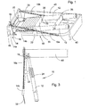
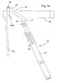
- FIGs. 13 and 14 another embodiment of the loft ladder assembly 10 is shown, which is intended to be used in hatch openings where the ladder cannot be accommodated in the hatch opening, but needs to be stored in the loft above the hatch opening.
- the loft ladder assembly shown in Figs. 13 and 14 is similar to the third embodiment of the loft ladder assembly shown in Figs. 8-12 , but without the carriage and the springs.
- the arrangement for holding the ladder 12 in the stowage position is similar to that of the second and the third embodiment, but the hook 122 is provided on the second lowermost rung 33 and a vertical bar 90 is received.
- the vertical bar 90 is mounted on braces 114a of the frame 14.
- the beams 70 are pivotably mounted on the bar 90.
- the hatch door 60 When the hatch door 60 is opened the ladder 12 will remain in the stowage position.
- the user pulls a strap connected to the lowermost rung and the beams 70 and the ladder 12 are pivoted past the over centre position to a horizontal position.
- the above procedure is essentially reversed.
- the ladder is collapsed.
- the rung 33 reaches the next higher rung, it will automatically release the locking pins of the next higher section to collapse that ladder section. The process is repeated until the entire ladder is collapsed.
- the beams can now be pivoted towards its horizontal position and once it passes the over-centre position the hook 122 of the lowermost rung can be placed onto the bar 50 whereupon the weight of the ladder will be fully supported by the frame 14.
- the strap is used to restrain the ladder so that it can be returned gently to its stowage position of Fig. 13 .
- the hatch door 60 can then be replaced or closed.
- the lower part of the ladder 12 can also be releasably connected to the hatch door 60 so that the ladder 12 will pivot as the hatch doors opens.
- the carriage 14b may carry or be connected to the hatch door.
- the carriage 14b may carry or be connected to the hatch door.
- springs in place of springs, one could use a catch to hold the carriage in its raised position.
Landscapes
- Engineering & Computer Science (AREA)
- Architecture (AREA)
- Civil Engineering (AREA)
- Structural Engineering (AREA)
- Ladders (AREA)
- Residential Or Office Buildings (AREA)
- Vehicle Interior And Exterior Ornaments, Soundproofing, And Insulation (AREA)
- Joints Allowing Movement (AREA)
Claims (10)
- Dachbodenleiteranordnung (10) für den Zugang zu einem Dachboden durch eine Lukenöffnung, wobei die Dachbodenleiteranordnung eine teleskopisch zusammenklappbare Leiter (12), die eine Verriegelungsanordnung hat, welche an einer Sprosse gelöst werden kann, um die Leiter zusammenzuklappen, und einen Rahmen (14) zum Montieren der Leiter innerhalb der Lukenöffnung aufweist, wobei der Rahmen eine Halterung (14a), die im Betrieb an der Lukenöffnung zu befestigen ist, Verbindungsanordnungen (28), um die Leiter schwenkbar mit dem Rahmen zu verbinden, und Halteanordnungen (22) aufweist, um die Leiter bezüglich des Rahmens zu halten, wenn die Leiter in einer zusammengeklappten Stellung ist, wobei die Leiter mit entsprechenden Halteanordnungen versehen ist, die mit den Halteanordnungen des Rahmens interagieren, dadurch gekennzeichnet, dass Tragbalken (70) schwenkbar mit dem Rahmen verbunden sind, und dass der oberste Abschnitt der Leiter durch die Verbindungsanordnungen schwenkbar mit den Tragbalken (70) verbunden ist.
- Dachbodenleiteranordnung (10) nach Anspruch 1, wobei ein Träger (14b) schwenkbar mit der Halterung (14a) verbunden ist, um das Gewicht der Leiter (12) in ihrer Verstaustellung zu tragen und die Leiter (12) daran zu hindern, unabsichtlich auszufahren.
- Dachbodenleiteranordnung (10) nach Anspruch 2, wobei, um die Leiter (12) daran zu hindern, unter der Wirkung ihres eigenen Gewichts auszufahren, der Träger (14b) mit einer Einrichtung (22) zum lösbaren Eingreifen in den untersten Abschnitt der Leiter versehen ist.
- Dachbodenleiteranordnung (10) nach Anspruch 3, wobei die Einrichtung (22) zum lösbaren Eingreifen in den untersten Abschnitt der Leiter (12) ein Paar von Haken (22) zur Aufnahme von Vorsprüngen aufweist, die seitlich von der zweituntersten Sprosse der Leiter (12) vorstehen.
- Dachbodenleiteranordnung nach Anspruch 1, wobei, um die Leiter (12) daran zu hindern, unter der Wirkung ihres eigenen Gewichts auszufahren, die Leiter (12) mit einer Einrichtung zum lösbaren Eingreifen in den Rahmen versehen ist.
- Dachbodenleiteranordnung nach Anspruch 1, wobei, um die Leiter (12) daran zu hindern, unter der Wirkung ihres eigenen Gewichts auszufahren, die Leiter (12) mit einer Einrichtung zum lösbaren Eingreifen in den Träger (14b) versehen ist, und wobei die Einrichtung zum lösbaren Eingreifen in den Träger (14b) einen Hakenabschnitt (122) auf einer untersten Sprosse der Leiter (12) zur Aufnahme einer senkrechten Stange (50) aufweist, die waagrechte Stangen (52) des Trägers verbindet.
- Dachbodenleiteranordnung nach einem der vorhergehenden Ansprüche, wobei die Tragbalken (70) mit einer Halteanordnung versehen sein können, zum Beispiel einer Feder oder einem Haken, um die Leiter daran zu hindern, unter der Wirkung ihres eigenen Gewichts auszufahren, wenn sie in einer Verstaustellung ist.
- Dachbodenleiteranordnung nach Anspruch 2-4, wobei der Träger (14b) mit der Halterung (14a) über mindestens eine Feder (16a) verbunden ist, die den Träger (14b) gegen die Wirkung des Gewichts der Leiter (12) in seine Verstaustellung drängt.
- Dachbodenleiteranordnung nach Anspruch 8, wobei jede Feder (16a) mit der Halterung (14a) und dem Träger (14b) derart verbunden ist, dass sie als Übertotpunkt-Kippfeder wirkt, um den Träger (14b) von der Leiter (12) wegzudrängen, wenn letztere ausgebracht ist.
- Dachbodenleiteranordnung nach einem beliebigen vorhergehenden Anspruch, wobei die Leiter (12) Verriegelungsstifte in die Sprossen (33) eingebaut hat, wobei die Stifte federvorgespannt sind, um sich seitlich nach außen in in den Holmen geformte Löcher zu bewegen, um die Abschnitte der Leiterstangen miteinander zu verriegeln, wenn die Leiter (12) in ihrer ausgefahrenen Stellung ist, wobei die Verriegelungsstifte für den nächsthöheren Abschnitt der Leiter zurückgezogen werden, wenn die die Verriegelungsstifte tragende Sprosse sich der darunterliegenden Sprosse annähert.
Applications Claiming Priority (2)
| Application Number | Priority Date | Filing Date | Title |
|---|---|---|---|
| GB0408475A GB2413148A (en) | 2004-04-16 | 2004-04-16 | Loft ladder assembly |
| PCT/SE2005/000550 WO2005100716A1 (en) | 2004-04-16 | 2005-04-15 | Loft ladder assembly |
Publications (2)
| Publication Number | Publication Date |
|---|---|
| EP2102429A1 EP2102429A1 (de) | 2009-09-23 |
| EP2102429B1 true EP2102429B1 (de) | 2011-08-03 |
Family
ID=32320920
Family Applications (1)
| Application Number | Title | Priority Date | Filing Date |
|---|---|---|---|
| EP05733732A Expired - Lifetime EP2102429B1 (de) | 2004-04-16 | 2005-04-15 | Dachbodenleiteranordnung |
Country Status (12)
| Country | Link |
|---|---|
| US (1) | US20070234654A1 (de) |
| EP (1) | EP2102429B1 (de) |
| JP (1) | JP2007532809A (de) |
| CN (1) | CN100447371C (de) |
| AT (1) | ATE519000T1 (de) |
| AU (1) | AU2005233496B2 (de) |
| CA (1) | CA2562409C (de) |
| DK (1) | DK2102429T3 (de) |
| ES (1) | ES2370645T3 (de) |
| GB (1) | GB2413148A (de) |
| NZ (1) | NZ550323A (de) |
| WO (1) | WO2005100716A1 (de) |
Cited By (1)
| Publication number | Priority date | Publication date | Assignee | Title |
|---|---|---|---|---|
| CN102444247A (zh) * | 2011-09-13 | 2012-05-09 | 宁波市鄞州千峰机械科技有限公司 | 缓坡起伏式教学楼专用楼梯 |
Families Citing this family (13)
| Publication number | Priority date | Publication date | Assignee | Title |
|---|---|---|---|---|
| US9863187B2 (en) * | 2006-07-27 | 2018-01-09 | Werner Co. | Tubular access ladder and method |
| US7967110B2 (en) * | 2006-07-27 | 2011-06-28 | Werner Co. | Tubular access ladder and method |
| JP2010513390A (ja) | 2006-12-20 | 2010-04-30 | ベーリンガー インゲルハイム インターナショナル ゲゼルシャフト ミット ベシュレンクテル ハフツング | 混合セロトニン受容体親和性を有する硫酸化ベンズイミダゾロン誘導体 |
| PL218283B1 (pl) * | 2010-01-18 | 2014-10-31 | Fakro Pp Spółka Z Ograniczoną Odpowiedzialnością | Schody składane, zwłaszcza osadzone w wysokiej ramie |
| US8555555B2 (en) * | 2010-03-27 | 2013-10-15 | Michael Cardwell | Automatic retractable hatch guard |
| US8695760B2 (en) * | 2011-01-28 | 2014-04-15 | Appropriate Combined Technologies, Llc | Telescoping pull-down attic ladder |
| CN104746816A (zh) * | 2013-12-31 | 2015-07-01 | 德胜(苏州)洋楼有限公司 | 一种木屋用隐藏式储藏梯 |
| US20150183308A1 (en) * | 2014-01-02 | 2015-07-02 | Gloria M. Buley | Roof hatch system |
| GB2532423A (en) * | 2014-11-18 | 2016-05-25 | Andrew Beard Michael | A cantilever mounted access device |
| GB2557286B (en) * | 2016-12-05 | 2018-12-19 | Vincent Cole Geoffrey | A Collapsible Ladder Apparatus |
| US11235852B2 (en) * | 2018-09-10 | 2022-02-01 | B/E Aerospace, Inc. | Bidirectional hatch for passenger rest compartment |
| CN109707124A (zh) * | 2018-11-13 | 2019-05-03 | 陈奕霏 | 一种建筑领域用阳台护栏 |
| US12054984B2 (en) * | 2020-06-15 | 2024-08-06 | Brian K. Gates | Escape door assembly for storm shelter |
Family Cites Families (15)
| Publication number | Priority date | Publication date | Assignee | Title |
|---|---|---|---|---|
| US1823510A (en) * | 1929-03-27 | 1931-09-15 | Peters | Extension ladder hook |
| GB496612A (en) * | 1936-11-14 | 1938-12-02 | Ursula Gleinser | Improvements in collapsible loft stairs |
| US2907401A (en) * | 1956-10-23 | 1959-10-06 | Wagner Johann | Folding stairs |
| US3051261A (en) * | 1960-07-18 | 1962-08-28 | Wel Bilt Products Company | Adjustable stairs |
| US3169603A (en) * | 1963-02-21 | 1965-02-16 | Sr John J Amic | Access ladder |
| US3490557A (en) * | 1967-07-07 | 1970-01-20 | Ralph J Auciello | Adjustable ladder construction for fire escape platforms and the like |
| US3653463A (en) * | 1970-06-22 | 1972-04-04 | E T Hannan & Associates Inc | Collapsible ladder arrangement |
| FR2300888A1 (fr) * | 1975-02-14 | 1976-09-10 | Monnerie Gerard | Nouveau dispositif de pliage d'escalier escamotable |
| US4180142A (en) * | 1978-05-25 | 1979-12-25 | Rocco Bruno, Jr | Emergency escape openable skylight |
| CA2080135C (en) * | 1990-04-10 | 1999-10-19 | James Thomas Weston | Collapsible ladder |
| US5495915A (en) * | 1990-04-10 | 1996-03-05 | Charles A. McDonnell | Collapsible ladder |
| GB2263932B (en) * | 1992-02-01 | 1995-06-28 | Telesteps Limited | Loft ladder |
| AT400737B (de) * | 1994-03-04 | 1996-03-25 | Minka Holz Und Metallverarbeit | Luke, insbesondere für dachbodentreppen |
| DE19717207C1 (de) * | 1997-04-24 | 1998-12-10 | Columbus Treppen Gmbh | Geländer für eine Bodentreppe |
| CN2571986Y (zh) * | 2002-09-25 | 2003-09-10 | 王国华 | 一种伸缩梯 |
-
2004
- 2004-04-16 GB GB0408475A patent/GB2413148A/en not_active Withdrawn
-
2005
- 2005-04-15 AT AT05733732T patent/ATE519000T1/de active
- 2005-04-15 WO PCT/SE2005/000550 patent/WO2005100716A1/en not_active Ceased
- 2005-04-15 AU AU2005233496A patent/AU2005233496B2/en not_active Expired
- 2005-04-15 CN CNB2005800172755A patent/CN100447371C/zh not_active Expired - Lifetime
- 2005-04-15 ES ES05733732T patent/ES2370645T3/es not_active Expired - Lifetime
- 2005-04-15 DK DK05733732.1T patent/DK2102429T3/da active
- 2005-04-15 CA CA2562409A patent/CA2562409C/en not_active Expired - Lifetime
- 2005-04-15 EP EP05733732A patent/EP2102429B1/de not_active Expired - Lifetime
- 2005-04-15 JP JP2007508305A patent/JP2007532809A/ja active Pending
- 2005-04-15 NZ NZ550323A patent/NZ550323A/en not_active IP Right Cessation
- 2005-04-15 US US11/578,525 patent/US20070234654A1/en not_active Abandoned
Cited By (1)
| Publication number | Priority date | Publication date | Assignee | Title |
|---|---|---|---|---|
| CN102444247A (zh) * | 2011-09-13 | 2012-05-09 | 宁波市鄞州千峰机械科技有限公司 | 缓坡起伏式教学楼专用楼梯 |
Also Published As
| Publication number | Publication date |
|---|---|
| CN100447371C (zh) | 2008-12-31 |
| JP2007532809A (ja) | 2007-11-15 |
| GB2413148A (en) | 2005-10-19 |
| WO2005100716A1 (en) | 2005-10-27 |
| ES2370645T3 (es) | 2011-12-21 |
| CA2562409A1 (en) | 2005-10-27 |
| CN1997800A (zh) | 2007-07-11 |
| GB0408475D0 (en) | 2004-05-19 |
| CA2562409C (en) | 2012-08-07 |
| DK2102429T3 (da) | 2011-10-24 |
| AU2005233496A1 (en) | 2005-10-27 |
| EP2102429A1 (de) | 2009-09-23 |
| US20070234654A1 (en) | 2007-10-11 |
| ATE519000T1 (de) | 2011-08-15 |
| NZ550323A (en) | 2009-10-30 |
| AU2005233496B2 (en) | 2011-03-24 |
Similar Documents
| Publication | Publication Date | Title |
|---|---|---|
| EP2102429B1 (de) | Dachbodenleiteranordnung | |
| US7182175B1 (en) | Retractable telescopic boat ladder | |
| CA2080135C (en) | Collapsible ladder | |
| US5495915A (en) | Collapsible ladder | |
| US10532919B2 (en) | Collapsible personnel basket for a crane | |
| US6971478B2 (en) | Tailgate ladder | |
| US11104559B2 (en) | Foldable personnel basket for a crane | |
| KR101242145B1 (ko) | 철도차량용 원터치 비상탈출 장치 | |
| EP1788167A1 (de) | Zusammenklappbares Gerüst | |
| US6102155A (en) | Combined window and emergency escape ladder | |
| EP1883739B1 (de) | Zusammenklappbare speichertreppenanordnung | |
| CA3016567C (en) | Foldable personnel basket for a crane | |
| US4243119A (en) | Folding building side mounted fire ladder | |
| US3845775A (en) | Car top tent | |
| WO1992008032A1 (en) | A collapsible escape ladder | |
| GB2263932A (en) | Loft ladder. | |
| US7159693B2 (en) | Window shutter escape ladder | |
| WO2007110888A1 (en) | Foldable stepladder with foldable handrail | |
| KR102441597B1 (ko) | 화재 대피용 사다리 장치 | |
| KR102441598B1 (ko) | 화재 대피 사다리용 설치박스 | |
| JPS6311280Y2 (de) | ||
| GB2150967A (en) | Collapsible ladder | |
| EP4405557B1 (de) | Tragbare leiter mit einer abstandsvorrichtung | |
| WO2005113908A1 (en) | Collapsable and unfoldable house structure | |
| JPS5831000B2 (ja) | 屋上出入口装置 |
Legal Events
| Date | Code | Title | Description |
|---|---|---|---|
| PUAI | Public reference made under article 153(3) epc to a published international application that has entered the european phase |
Free format text: ORIGINAL CODE: 0009012 |
|
| 17P | Request for examination filed |
Effective date: 20070205 |
|
| AK | Designated contracting states |
Kind code of ref document: A1 Designated state(s): AT BE BG CH CY CZ DE DK EE ES FI FR GB GR HU IE IS IT LI LT LU MC NL PL PT RO SE SI SK TR |
|
| 17Q | First examination report despatched |
Effective date: 20100426 |
|
| GRAP | Despatch of communication of intention to grant a patent |
Free format text: ORIGINAL CODE: EPIDOSNIGR1 |
|
| GRAS | Grant fee paid |
Free format text: ORIGINAL CODE: EPIDOSNIGR3 |
|
| GRAA | (expected) grant |
Free format text: ORIGINAL CODE: 0009210 |
|
| AK | Designated contracting states |
Kind code of ref document: B1 Designated state(s): AT BE BG CH CY CZ DE DK EE ES FI FR GB GR HU IE IS IT LI LT LU MC NL PL PT RO SE SI SK TR |
|
| REG | Reference to a national code |
Ref country code: GB Ref legal event code: FG4D |
|
| REG | Reference to a national code |
Ref country code: CH Ref legal event code: EP |
|
| REG | Reference to a national code |
Ref country code: IE Ref legal event code: FG4D |
|
| REG | Reference to a national code |
Ref country code: DE Ref legal event code: R096 Ref document number: 602005029312 Country of ref document: DE Effective date: 20110929 |
|
| REG | Reference to a national code |
Ref country code: DK Ref legal event code: T3 |
|
| REG | Reference to a national code |
Ref country code: NL Ref legal event code: T3 |
|
| REG | Reference to a national code |
Ref country code: CH Ref legal event code: NV Representative=s name: RENTSCH PARTNER AG |
|
| REG | Reference to a national code |
Ref country code: SE Ref legal event code: TRGR |
|
| REG | Reference to a national code |
Ref country code: ES Ref legal event code: FG2A Ref document number: 2370645 Country of ref document: ES Kind code of ref document: T3 Effective date: 20111221 |
|
| LTIE | Lt: invalidation of european patent or patent extension |
Effective date: 20110803 |
|
| PG25 | Lapsed in a contracting state [announced via postgrant information from national office to epo] |
Ref country code: LT Free format text: LAPSE BECAUSE OF FAILURE TO SUBMIT A TRANSLATION OF THE DESCRIPTION OR TO PAY THE FEE WITHIN THE PRESCRIBED TIME-LIMIT Effective date: 20110803 Ref country code: IS Free format text: LAPSE BECAUSE OF FAILURE TO SUBMIT A TRANSLATION OF THE DESCRIPTION OR TO PAY THE FEE WITHIN THE PRESCRIBED TIME-LIMIT Effective date: 20111203 Ref country code: PT Free format text: LAPSE BECAUSE OF FAILURE TO SUBMIT A TRANSLATION OF THE DESCRIPTION OR TO PAY THE FEE WITHIN THE PRESCRIBED TIME-LIMIT Effective date: 20111205 |
|
| PG25 | Lapsed in a contracting state [announced via postgrant information from national office to epo] |
Ref country code: CY Free format text: LAPSE BECAUSE OF FAILURE TO SUBMIT A TRANSLATION OF THE DESCRIPTION OR TO PAY THE FEE WITHIN THE PRESCRIBED TIME-LIMIT Effective date: 20110803 Ref country code: GR Free format text: LAPSE BECAUSE OF FAILURE TO SUBMIT A TRANSLATION OF THE DESCRIPTION OR TO PAY THE FEE WITHIN THE PRESCRIBED TIME-LIMIT Effective date: 20111104 Ref country code: PL Free format text: LAPSE BECAUSE OF FAILURE TO SUBMIT A TRANSLATION OF THE DESCRIPTION OR TO PAY THE FEE WITHIN THE PRESCRIBED TIME-LIMIT Effective date: 20110803 Ref country code: SI Free format text: LAPSE BECAUSE OF FAILURE TO SUBMIT A TRANSLATION OF THE DESCRIPTION OR TO PAY THE FEE WITHIN THE PRESCRIBED TIME-LIMIT Effective date: 20110803 |
|
| PG25 | Lapsed in a contracting state [announced via postgrant information from national office to epo] |
Ref country code: CZ Free format text: LAPSE BECAUSE OF FAILURE TO SUBMIT A TRANSLATION OF THE DESCRIPTION OR TO PAY THE FEE WITHIN THE PRESCRIBED TIME-LIMIT Effective date: 20110803 Ref country code: SK Free format text: LAPSE BECAUSE OF FAILURE TO SUBMIT A TRANSLATION OF THE DESCRIPTION OR TO PAY THE FEE WITHIN THE PRESCRIBED TIME-LIMIT Effective date: 20110803 |
|
| PG25 | Lapsed in a contracting state [announced via postgrant information from national office to epo] |
Ref country code: EE Free format text: LAPSE BECAUSE OF FAILURE TO SUBMIT A TRANSLATION OF THE DESCRIPTION OR TO PAY THE FEE WITHIN THE PRESCRIBED TIME-LIMIT Effective date: 20110803 Ref country code: RO Free format text: LAPSE BECAUSE OF FAILURE TO SUBMIT A TRANSLATION OF THE DESCRIPTION OR TO PAY THE FEE WITHIN THE PRESCRIBED TIME-LIMIT Effective date: 20110803 |
|
| PLBE | No opposition filed within time limit |
Free format text: ORIGINAL CODE: 0009261 |
|
| STAA | Information on the status of an ep patent application or granted ep patent |
Free format text: STATUS: NO OPPOSITION FILED WITHIN TIME LIMIT |
|
| 26N | No opposition filed |
Effective date: 20120504 |
|
| REG | Reference to a national code |
Ref country code: DE Ref legal event code: R097 Ref document number: 602005029312 Country of ref document: DE Effective date: 20120504 |
|
| PG25 | Lapsed in a contracting state [announced via postgrant information from national office to epo] |
Ref country code: MC Free format text: LAPSE BECAUSE OF NON-PAYMENT OF DUE FEES Effective date: 20120430 |
|
| REG | Reference to a national code |
Ref country code: IE Ref legal event code: MM4A |
|
| PG25 | Lapsed in a contracting state [announced via postgrant information from national office to epo] |
Ref country code: IE Free format text: LAPSE BECAUSE OF NON-PAYMENT OF DUE FEES Effective date: 20120415 |
|
| PG25 | Lapsed in a contracting state [announced via postgrant information from national office to epo] |
Ref country code: BG Free format text: LAPSE BECAUSE OF FAILURE TO SUBMIT A TRANSLATION OF THE DESCRIPTION OR TO PAY THE FEE WITHIN THE PRESCRIBED TIME-LIMIT Effective date: 20111103 |
|
| PG25 | Lapsed in a contracting state [announced via postgrant information from national office to epo] |
Ref country code: TR Free format text: LAPSE BECAUSE OF FAILURE TO SUBMIT A TRANSLATION OF THE DESCRIPTION OR TO PAY THE FEE WITHIN THE PRESCRIBED TIME-LIMIT Effective date: 20110803 |
|
| PG25 | Lapsed in a contracting state [announced via postgrant information from national office to epo] |
Ref country code: LU Free format text: LAPSE BECAUSE OF NON-PAYMENT OF DUE FEES Effective date: 20120415 |
|
| PG25 | Lapsed in a contracting state [announced via postgrant information from national office to epo] |
Ref country code: HU Free format text: LAPSE BECAUSE OF FAILURE TO SUBMIT A TRANSLATION OF THE DESCRIPTION OR TO PAY THE FEE WITHIN THE PRESCRIBED TIME-LIMIT Effective date: 20050415 |
|
| REG | Reference to a national code |
Ref country code: FR Ref legal event code: PLFP Year of fee payment: 12 |
|
| REG | Reference to a national code |
Ref country code: FR Ref legal event code: PLFP Year of fee payment: 13 |
|
| REG | Reference to a national code |
Ref country code: CH Ref legal event code: PCAR Free format text: NEW ADDRESS: BELLERIVESTRASSE 203 POSTFACH, 8034 ZUERICH (CH) |
|
| REG | Reference to a national code |
Ref country code: FR Ref legal event code: PLFP Year of fee payment: 14 |
|
| PGFP | Annual fee paid to national office [announced via postgrant information from national office to epo] |
Ref country code: CH Payment date: 20180410 Year of fee payment: 14 Ref country code: ES Payment date: 20180521 Year of fee payment: 14 Ref country code: FI Payment date: 20180409 Year of fee payment: 14 Ref country code: DK Payment date: 20180412 Year of fee payment: 14 |
|
| PGFP | Annual fee paid to national office [announced via postgrant information from national office to epo] |
Ref country code: AT Payment date: 20180409 Year of fee payment: 14 Ref country code: BE Payment date: 20180418 Year of fee payment: 14 |
|
| REG | Reference to a national code |
Ref country code: CH Ref legal event code: PL |
|
| REG | Reference to a national code |
Ref country code: DK Ref legal event code: EBP Effective date: 20190430 |
|
| REG | Reference to a national code |
Ref country code: AT Ref legal event code: MM01 Ref document number: 519000 Country of ref document: AT Kind code of ref document: T Effective date: 20190415 |
|
| REG | Reference to a national code |
Ref country code: BE Ref legal event code: MM Effective date: 20190430 |
|
| PG25 | Lapsed in a contracting state [announced via postgrant information from national office to epo] |
Ref country code: AT Free format text: LAPSE BECAUSE OF NON-PAYMENT OF DUE FEES Effective date: 20190415 Ref country code: CH Free format text: LAPSE BECAUSE OF NON-PAYMENT OF DUE FEES Effective date: 20190430 Ref country code: LI Free format text: LAPSE BECAUSE OF NON-PAYMENT OF DUE FEES Effective date: 20190430 Ref country code: FI Free format text: LAPSE BECAUSE OF NON-PAYMENT OF DUE FEES Effective date: 20190415 |
|
| PG25 | Lapsed in a contracting state [announced via postgrant information from national office to epo] |
Ref country code: BE Free format text: LAPSE BECAUSE OF NON-PAYMENT OF DUE FEES Effective date: 20190430 |
|
| PG25 | Lapsed in a contracting state [announced via postgrant information from national office to epo] |
Ref country code: IT Free format text: LAPSE BECAUSE OF NON-PAYMENT OF DUE FEES Effective date: 20190415 Ref country code: DK Free format text: LAPSE BECAUSE OF NON-PAYMENT OF DUE FEES Effective date: 20190430 |
|
| REG | Reference to a national code |
Ref country code: ES Ref legal event code: FD2A Effective date: 20200831 |
|
| PG25 | Lapsed in a contracting state [announced via postgrant information from national office to epo] |
Ref country code: ES Free format text: LAPSE BECAUSE OF NON-PAYMENT OF DUE FEES Effective date: 20190416 |
|
| P01 | Opt-out of the competence of the unified patent court (upc) registered |
Effective date: 20230421 |
|
| PGFP | Annual fee paid to national office [announced via postgrant information from national office to epo] |
Ref country code: NL Payment date: 20240412 Year of fee payment: 20 |
|
| PGFP | Annual fee paid to national office [announced via postgrant information from national office to epo] |
Ref country code: GB Payment date: 20240411 Year of fee payment: 20 |
|
| PGFP | Annual fee paid to national office [announced via postgrant information from national office to epo] |
Ref country code: DE Payment date: 20240408 Year of fee payment: 20 |
|
| PGFP | Annual fee paid to national office [announced via postgrant information from national office to epo] |
Ref country code: FR Payment date: 20240411 Year of fee payment: 20 |
|
| PGFP | Annual fee paid to national office [announced via postgrant information from national office to epo] |
Ref country code: SE Payment date: 20240415 Year of fee payment: 20 |
|
| REG | Reference to a national code |
Ref country code: DE Ref legal event code: R071 Ref document number: 602005029312 Country of ref document: DE |
|
| REG | Reference to a national code |
Ref country code: NL Ref legal event code: MK Effective date: 20250414 |
|
| REG | Reference to a national code |
Ref country code: GB Ref legal event code: PE20 Expiry date: 20250414 |
|
| REG | Reference to a national code |
Ref country code: SE Ref legal event code: EUG |
|
| PG25 | Lapsed in a contracting state [announced via postgrant information from national office to epo] |
Ref country code: GB Free format text: LAPSE BECAUSE OF EXPIRATION OF PROTECTION Effective date: 20250414 |