EP2102464B1 - Vorrichtung zum befördern fluider medien bei tiefen temperaturen - Google Patents
Vorrichtung zum befördern fluider medien bei tiefen temperaturen Download PDFInfo
- Publication number
- EP2102464B1 EP2102464B1 EP07821652A EP07821652A EP2102464B1 EP 2102464 B1 EP2102464 B1 EP 2102464B1 EP 07821652 A EP07821652 A EP 07821652A EP 07821652 A EP07821652 A EP 07821652A EP 2102464 B1 EP2102464 B1 EP 2102464B1
- Authority
- EP
- European Patent Office
- Prior art keywords
- connecting piece
- heat
- module
- conducting sleeve
- line
- Prior art date
- Legal status (The legal status is an assumption and is not a legal conclusion. Google has not performed a legal analysis and makes no representation as to the accuracy of the status listed.)
- Active
Links
Images
Classifications
-
- F—MECHANICAL ENGINEERING; LIGHTING; HEATING; WEAPONS; BLASTING
- F01—MACHINES OR ENGINES IN GENERAL; ENGINE PLANTS IN GENERAL; STEAM ENGINES
- F01N—GAS-FLOW SILENCERS OR EXHAUST APPARATUS FOR MACHINES OR ENGINES IN GENERAL; GAS-FLOW SILENCERS OR EXHAUST APPARATUS FOR INTERNAL-COMBUSTION ENGINES
- F01N3/00—Exhaust or silencing apparatus having means for purifying, rendering innocuous, or otherwise treating exhaust
- F01N3/08—Exhaust or silencing apparatus having means for purifying, rendering innocuous, or otherwise treating exhaust for rendering innocuous
- F01N3/10—Exhaust or silencing apparatus having means for purifying, rendering innocuous, or otherwise treating exhaust for rendering innocuous by thermal or catalytic conversion of noxious components of exhaust
- F01N3/18—Exhaust or silencing apparatus having means for purifying, rendering innocuous, or otherwise treating exhaust for rendering innocuous by thermal or catalytic conversion of noxious components of exhaust characterised by methods of operation; Control
- F01N3/20—Exhaust or silencing apparatus having means for purifying, rendering innocuous, or otherwise treating exhaust for rendering innocuous by thermal or catalytic conversion of noxious components of exhaust characterised by methods of operation; Control specially adapted for catalytic conversion
- F01N3/206—Adding periodically or continuously substances to exhaust gases for promoting purification, e.g. catalytic material in liquid form, NOx reducing agents
- F01N3/2066—Selective catalytic reduction [SCR]
-
- F—MECHANICAL ENGINEERING; LIGHTING; HEATING; WEAPONS; BLASTING
- F16—ENGINEERING ELEMENTS AND UNITS; GENERAL MEASURES FOR PRODUCING AND MAINTAINING EFFECTIVE FUNCTIONING OF MACHINES OR INSTALLATIONS; THERMAL INSULATION IN GENERAL
- F16L—PIPES; JOINTS OR FITTINGS FOR PIPES; SUPPORTS FOR PIPES, CABLES OR PROTECTIVE TUBING; MEANS FOR THERMAL INSULATION IN GENERAL
- F16L53/00—Heating of pipes or pipe systems; Cooling of pipes or pipe systems
- F16L53/30—Heating of pipes or pipe systems
- F16L53/35—Ohmic-resistance heating
- F16L53/38—Ohmic-resistance heating using elongate electric heating elements, e.g. wires or ribbons
-
- F—MECHANICAL ENGINEERING; LIGHTING; HEATING; WEAPONS; BLASTING
- F01—MACHINES OR ENGINES IN GENERAL; ENGINE PLANTS IN GENERAL; STEAM ENGINES
- F01N—GAS-FLOW SILENCERS OR EXHAUST APPARATUS FOR MACHINES OR ENGINES IN GENERAL; GAS-FLOW SILENCERS OR EXHAUST APPARATUS FOR INTERNAL-COMBUSTION ENGINES
- F01N2610/00—Adding substances to exhaust gases
- F01N2610/02—Adding substances to exhaust gases the substance being ammonia or urea
-
- F—MECHANICAL ENGINEERING; LIGHTING; HEATING; WEAPONS; BLASTING
- F01—MACHINES OR ENGINES IN GENERAL; ENGINE PLANTS IN GENERAL; STEAM ENGINES
- F01N—GAS-FLOW SILENCERS OR EXHAUST APPARATUS FOR MACHINES OR ENGINES IN GENERAL; GAS-FLOW SILENCERS OR EXHAUST APPARATUS FOR INTERNAL-COMBUSTION ENGINES
- F01N2610/00—Adding substances to exhaust gases
- F01N2610/10—Adding substances to exhaust gases the substance being heated, e.g. by heating tank or supply line of the added substance
-
- F—MECHANICAL ENGINEERING; LIGHTING; HEATING; WEAPONS; BLASTING
- F01—MACHINES OR ENGINES IN GENERAL; ENGINE PLANTS IN GENERAL; STEAM ENGINES
- F01N—GAS-FLOW SILENCERS OR EXHAUST APPARATUS FOR MACHINES OR ENGINES IN GENERAL; GAS-FLOW SILENCERS OR EXHAUST APPARATUS FOR INTERNAL-COMBUSTION ENGINES
- F01N2610/00—Adding substances to exhaust gases
- F01N2610/14—Arrangements for the supply of substances, e.g. conduits
-
- F—MECHANICAL ENGINEERING; LIGHTING; HEATING; WEAPONS; BLASTING
- F01—MACHINES OR ENGINES IN GENERAL; ENGINE PLANTS IN GENERAL; STEAM ENGINES
- F01N—GAS-FLOW SILENCERS OR EXHAUST APPARATUS FOR MACHINES OR ENGINES IN GENERAL; GAS-FLOW SILENCERS OR EXHAUST APPARATUS FOR INTERNAL-COMBUSTION ENGINES
- F01N2610/00—Adding substances to exhaust gases
- F01N2610/14—Arrangements for the supply of substances, e.g. conduits
- F01N2610/1486—Means to prevent the substance from freezing
-
- Y—GENERAL TAGGING OF NEW TECHNOLOGICAL DEVELOPMENTS; GENERAL TAGGING OF CROSS-SECTIONAL TECHNOLOGIES SPANNING OVER SEVERAL SECTIONS OF THE IPC; TECHNICAL SUBJECTS COVERED BY FORMER USPC CROSS-REFERENCE ART COLLECTIONS [XRACs] AND DIGESTS
- Y02—TECHNOLOGIES OR APPLICATIONS FOR MITIGATION OR ADAPTATION AGAINST CLIMATE CHANGE
- Y02T—CLIMATE CHANGE MITIGATION TECHNOLOGIES RELATED TO TRANSPORTATION
- Y02T10/00—Road transport of goods or passengers
- Y02T10/10—Internal combustion engine [ICE] based vehicles
- Y02T10/12—Improving ICE efficiencies
-
- Y—GENERAL TAGGING OF NEW TECHNOLOGICAL DEVELOPMENTS; GENERAL TAGGING OF CROSS-SECTIONAL TECHNOLOGIES SPANNING OVER SEVERAL SECTIONS OF THE IPC; TECHNICAL SUBJECTS COVERED BY FORMER USPC CROSS-REFERENCE ART COLLECTIONS [XRACs] AND DIGESTS
- Y10—TECHNICAL SUBJECTS COVERED BY FORMER USPC
- Y10T—TECHNICAL SUBJECTS COVERED BY FORMER US CLASSIFICATION
- Y10T137/00—Fluid handling
- Y10T137/6416—With heating or cooling of the system
-
- Y—GENERAL TAGGING OF NEW TECHNOLOGICAL DEVELOPMENTS; GENERAL TAGGING OF CROSS-SECTIONAL TECHNOLOGIES SPANNING OVER SEVERAL SECTIONS OF THE IPC; TECHNICAL SUBJECTS COVERED BY FORMER USPC CROSS-REFERENCE ART COLLECTIONS [XRACs] AND DIGESTS
- Y10—TECHNICAL SUBJECTS COVERED BY FORMER USPC
- Y10T—TECHNICAL SUBJECTS COVERED BY FORMER US CLASSIFICATION
- Y10T137/00—Fluid handling
- Y10T137/6416—With heating or cooling of the system
- Y10T137/6606—With electric heating element
Definitions
- the invention relates to a device for conveying fluid media, which is particularly suitable at low temperatures, that is, temperatures below the fixed point of the fluid media.
- Such devices are used in particular in the context of systems for dosing liquid reducing agent in exhaust systems of motor vehicles to reduce pollutants in the exhaust gas.
- a selective catalytic reduction is performed, in which the nitrogen oxides are reduced by means of reducing agents to nitrogen and water.
- reducing agent for example, an aqueous urea solution is used.
- the reducing agent is usually stored in a tank and conveyed via a line from the tank to a metering module, with which the reducing agent is injected, for example, into the exhaust pipe.
- a metering module with which the reducing agent is injected, for example, into the exhaust pipe.
- An example of such a device is in DE 10 2004 062 603 B3 shown.
- liquid reducing agents customary today freeze depending on the (optionally) added anti-freeze agent about -1 ° C and -40 ° C.
- the described system is often not immediately available under certain environmental conditions. Therefore, special heating measures are usually provided to convert the reducing agent in the system in the liquid state.
- the delivery module and / or the lines used are often designed to be fully or partially heated. These measures usually ensure that the system is up and running after a set time.
- a device for conveying a fluid medium which advantageously further develops devices known from the prior art and avoids the interface problem described above.
- the fluid media may be of different nature, that is, in particular gaseous or liquid nature, wherein preferably the device is adapted to the transport of one or more liquid reducing agents to reduce the emission of pollutants in a motor vehicle.
- the proposed device provides an interface between a heated delivery line and a system component, which may also be designed as a hydraulic interface or hydraulic connector.
- the system component may in particular comprise a delivery module or a working container or else a further delivery line.
- a connection to other types of system components of a conveyor system for conveying fluid media is conceivable, such as on Distributor or the like, as well as a connection to a combination of such system components.
- the interface can be defrosted within a very short time by appropriate heating measures, without the need for elaborate heating measures in the interface itself. Analog can be prevented by low heat performance, a freezing of the interface.
- the availability of the device is greatly increased by the inventive design. Waiting times associated with thawing the interface are significantly shortened, which increases operability, particularly in the automotive industry, as well as ease of use.
- the device in addition to a delivery line-side conduit fitting and a system component-side module fitting (which together interface and provide mechanical / fluidic coupling functionality), the device includes a heat-conducting sleeve which transfers heat from the heated delivery line and / or heated one Internal area of the system component transmits to the interface.
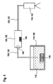
- FIG. 1 is a schematic representation of an embodiment of a system 110 for dosing a liquid reducing agent 112 from a working container 114 via a dosing module 116 in the exhaust gas of an internal combustion engine (in particular in the range of a catalyst) shown.
- the metering module 116 can be designed, for example, as in the aforementioned prior art, for example as a pressure-controlled injection valve.
- the working container 114 is provided in the system 110 shown here with a container heater 118, by means of which the liquid reducing agent 112 can be brought to a working temperature and / or by means of which a freezing of the liquid reducing agent 112 in the working container 114 can be prevented.
- System component is to be understood in particular as meaning components for receiving and / or transporting the liquid reducing agent 112 (or analogously other fluid media). are suitable, so have corresponding cavities and / or lines. Accordingly, as system components 122, for example, the working container 114, the dosing module 116, the delivery lines 120 themselves (for example in the context of a coupling of two different lines) or a delivery module 124 are considered, to which a delivery line 120 to connect in the context of an assembly of the system 110 is.
- the delivery module 124 may include, for example, a pump (eg, a diaphragm pump), and preferably a heating element 126 for thawing the liquid reducing agent 112 or for obtaining an operating temperature, respectively.
- the delivery lines 120 are designed to be heated accordingly.
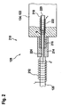
- FIG. 2 a device 210 according to the invention for conveying a fluid medium is shown.
- this device comprises an interface between a delivery line 120 and the delivery module 124, which in FIG. 1 symbolically denoted by the reference numeral 128.
- the delivery lines 120 As described above, however, other interfaces are also possible, for example interfaces of the delivery lines 120 with the working container 114, further delivery lines 120 or the dosing module 116.
- the delivery line 120 has a line heater 212, which in FIG. 2 symbolically represented as a heating coil.
- a line heater 212 which in FIG. 2 symbolically represented as a heating coil.
- the delivery line 120 itself may, for example, be made of a plastic material, for example a conventional or else a thermally conductive plastic material (for example a plastic filled with a thermally conductive filler), or, for example, also a metallic material.
- a line connection piece 214 is arranged, which is connected to the delivery line 120.
- the line fitting 214 is not detected by the line heater 212 and is thus largely unheated.
- the conduit fitting 214 may be formed of, for example, plastic or metal (such as aluminum or brass) and represents the female connector portion of the interface 128.
- the delivery module 124 has a stub-shaped module connection piece 216 arranged on the housing of the delivery module 124.
- This module connector 216 forms the male part of the interface 128 and is designed to be inserted into the end of the lead connector 214.
- this module connection piece 216 may in turn be made of plastic or a metallic material.
- a further line 218 is arranged, with an inner area 220.
- this inner area 220 is in fluid communication with the interior of the delivery line 120. If, instead of the delivery module 124 as system component 122, another fluidic element, such as the working container 114, is used, the interior of this container will take the place of the inner region 120.
- a module heater 222 is further arranged, which in the schematic representation according to FIG. 2 is designed as a heating coil. Also, other types of embodiment of this module heater 222 are conceivable, for example, heating windings in the form of electric blankets, immersed in the fluid medium heaters or the like.
- the module heater 222 serves to apply heat to the line 218 and its inner area 220 in order to prevent freezing of the fluid medium or to thaw it.
- the interface 128 may, however, in whole or in part, with an in FIG. 2 not shown thermal insulation, such as a sheath (for example, fabric, fiberglass or the like) to be surrounded.
- a sheath for example, fabric, fiberglass or the like
- this thermal sheath or the material used therein has a thermal conductivity of less than 0.1 W / (m * K).
- the device 210 has a heat-conducting sleeve 224, which is inserted into the fluidic connection between the delivery line 120 and the line 218.
- This heat conducting sleeve 224 is integrally formed, but also multi-part configurations of the réelleleithülse 224 are conceivable, for example in the form of a line connecting piece 214 associated sleeve part and the module connecting piece 216 associated sleeve part.
- a cylindrical dressingleithülse 224 is used, which itself has an inner cavity.
- the heat-conducting sleeve 224 establishes a fluidic connection between the conveying line and the inner region 220.
- more complex flow geometries of the heat conducting sleeve 224 could be used.
- a material with a thermal conductivity of more than 100 W / (m * K) is used as the material for the heat conducting sleeve 224.
- metals have proven to be particularly suitable, such as copper, aluminum, brass, zinc, silver, gold, magnesium or tungsten and alloys of these metals.
- these metals may also be coated with a preferably thin (eg, not more than 500 micrometers thick) chemically resistant protective layer (eg, Teflon or other plastic or multilayer plastic composition) for protection against the liquid reducing agent 112.
- a preferably thin (eg, not more than 500 micrometers thick) chemically resistant protective layer eg, Teflon or other plastic or multilayer plastic composition
- graphite or thermally conductive plastics for example plastics filled with graphite or metal particles, as the material for the heat-conducting sleeve 224.
- the heat conducting sleeve 224 thermally contacts at least one of the heated areas by the heating elements 212 and 222 to transfer heat from these areas to the interface 124.
- This thermal contact can be configured both in the form of heat conduction and in the form of thermal radiation.
- the heat transfer coefficient should be greater than for the heat transfer between the delivery line 12 and line connector 214 or module connector 216 and heated inner region 220th
- the heat conducting sleeve 224 may be formed as a tube with a press fit into the delivery line 120.
- the heat conducting sleeve 224 may also be inserted into the conduit 218 in the inner region 220 of the conveying module 124. In this way, a fast and secure thawing of the interface 128 is ensured, or a freezing of this interface 128 can be easily prevented.
- this configuration of the interface 128 has a positive effect.
- the interface 128 is thus designed such that the two connecting pieces 214, 216 assume the mechanical function of the connection, and, optionally, a fluidic function (for example in the context of a hydraulic connection).
- the heat transfer to the interface 128 or the heating thereof, however, is taken over by the formed as a separate component nickel pulpose 224, which also assumes fluidic functions simultaneously.
- the materials of the banks 214, 216 can thus, according to these separate functionalities, be optimized separately, according to the respective requirements.
- the coupling of the interface 128 also deviates from the in FIG. 2 shown coupling with simple two connecting pieces 214, 218 may be configured, for example using an intermediate piece (adapter), ie in the form of an indirect coupling.
- the sauceleithülse 224 be designed such that it also completely or partially penetrates the intermediate piece to prevent freezing of this intermediate piece or to allow thawing of this intermediate piece without the use of additional heating in the intermediate piece.
Landscapes
- Engineering & Computer Science (AREA)
- Chemical & Material Sciences (AREA)
- General Engineering & Computer Science (AREA)
- Chemical Kinetics & Catalysis (AREA)
- Mechanical Engineering (AREA)
- Health & Medical Sciences (AREA)
- Toxicology (AREA)
- Combustion & Propulsion (AREA)
- Exhaust Gas After Treatment (AREA)
- Pipe Accessories (AREA)
- Automatic Analysis And Handling Materials Therefor (AREA)
Description
- Die Erfindung betrifft eine Vorrichtung zum Befördern fluider Medien, welche insbesondere auch bei tiefen Temperaturen, das heißt Temperaturen auch unterhalb des Festpunkts der fluiden Medien, geeignet ist. Derartige Vorrichtungen werden insbesondere im Rahmen von Systemen zum Dosieren flüssiger Reduktionsmittel in Abgassysteme von Kraftfahrzeugen zur Reduzierung von Schadstoffen im Abgas eingesetzt.
- Bei Verbrennungskraftmaschinen, insbesondere bei dieselbetriebenen Verbrennungskraftmaschinen, muss aufgrund der in den nächsten Jahren anstehenden verschärften Abgasgesetzgebung unter anderem der Anteil an Stickoxiden im Abgas reduziert werden. Zur Reduzierung des Stickoxid-Anteils im Abgas wird zum Beispiel eine selektive katalytische Reduktion (SCR) durchgeführt, bei welcher die Stickoxide mit Hilfe von Reduktionsmitteln zu Stickstoff und Wasser reduziert werden. Als Reduktionsmittel wird zum Beispiel eine wässrige Harnstofflösung eingesetzt.
- Das Reduktionsmittel wird üblicherweise in einem Tank gelagert und über eine Leitung vom Tank zu einem Dosiermodul befördert, mit dem das Reduktionsmittel zum Beispiel in das Abgasrohr eingespritzt wird. Ein Beispiel einer derartigen Vorrichtung ist in
DE 10 2004 062 603 B3 dargestellt. - Anstelle des in
DE 10 2004 062 603 B3 dargestellten Systems, bei welchem das Reduktionsmittel unter Zugabe von Druckluft in den Katalysator eingebracht wird, werden häufig auch einfachere Systeme eingesetzt, bei welchen das flüssige Reduktionsmittel aus einem Tank (welcher beispielsweise beheizt ausgestaltet sein kann) über ein Fördermodul und entsprechende Leitungen zum Dosiermodul gefördert wird, um dort in das Abgas eingespritzt zu werden. - Die heute üblichen flüssigen Reduktionsmittel (beispielsweise die bereits genannte wässrige Harnstofflösung) gefrieren jedoch je nach (optional) zugesetztem Anti-Frostmittel zwischen ca. -1 °C und -40 °C. Somit ist das beschriebene System häufig bei bestimmten Umgebungsbedingungen nicht unmittelbar verfügbar. Daher werden üblicherweise spezielle Heizmaßnahmen vorgesehen, um das Reduktionsmittel im System in den flüssigen Zustand zu überführen. Neben dem Tank werden daher häufig auch das Fördermodul und/oder die verwendeten Leitungen ganz oder teilweise beheizt ausgestaltet. Mit diesen Maßnahmen ist in der Regel gewährleistet, dass das System nach einer vorgegebenen Zeit betriebsbereit ist.
- Trotz der genannten Heizmaßnahmen besteht jedoch eine häufig auftretende Problematik darin, dass die Schnittstelle zwischen einzelnen Systemkomponenten, insbesondere den Komponenten Tank, Fördermodul und Leitung beziehungsweise Leitungsabschnitten, aufgrund der vorgegebenen Beschaffenheit der Heizung nur schlecht aufgetaut werden kann. Selbst wenn die einzelnen Systemkomponenten selbst aufgetaut sind, sind in vielen Fällen die Schnittstellen noch eingefroren, was die Verfügbarkeit des Systems vermindert oder sogar verhindert. Dies beruht insbesondere darauf, dass die elektrische Heizung nur mit großem Aufwand an die Schnittstelle herangeführt werden kann.
- In vielen Fällen werden für die Schnittstellen hydraulische Anschlussstücke benötigt. Die Beheizung dieser hydraulischen Anschlussstücke, welche in der Regel nicht Bestandteil des beziehungsweise der Heizkreise der Systemkomponenten sind, hat sich als überaus schwierig erwiesen.
- Erfindungsgemäß wird daher eine Vorrichtung zum Befördern eines fluiden Mediums vorgeschlagen, welche aus dem Stand der Technik bekannte Vorrichtungen vorteilhaft weiterbildet und die oben beschriebene Schnittstellenproblematik vermeidet. Die fluiden Medien können dabei unterschiedlicher Natur sein, also insbesondere gasförmiger oder flüssiger Natur, wobei vorzugsweise die Vorrichtung auf die Beförderung eines oder mehrerer flüssiger Reduktionsmittel zur Verminderung der Schadstoffemission in einem Kraftfahrzeug eingerichtet ist.
- Die vorgeschlagene Vorrichtung stellt eine Schnittstelle zwischen einer beheizten Förderleitung und einer Systemkomponente bereit, welche auch als hydraulische Schnittstelle beziehungsweise hydraulisches Anschlussstück ausgebildet sein kann. Die Systemkomponente kann insbesondere ein Fördermodul oder einen Arbeitsbehälter oder auch eine weitere Förderleitung umfassen. Auch ein Anschluss an andere Arten von Systemkomponenten eines Fördersystems zur Beförderung fluider Medien ist jedoch denkbar, wie beispielsweise an Verteiler oder ähnliches, sowie einen Anschluss an eine Kombination derartiger Systemkomponenten.
- Die Schnittstelle ist innerhalb kürzester Zeit durch entsprechende Heizmaßnahmen auftaubar, ohne dass aufwändige Heizmaßnahmen in der Schnittstelle selbst vorgesehen sein müssen. Analog kann durch geringe Heizleistungen ein Einfrieren der Schnittstelle verhindert werden. Die Verfügbarkeit der Vorrichtung wird durch die erfindungsgemäße Ausgestaltung stark erhöht. Wartezeiten, die mit einem Auftauen der Schnittstelle verbunden sind, werden erheblich verkürzt, was die Einsatzfähigkeit insbesondere im Automobilbereich sowie die Benutzerfreundlichkeit erhöht.
- Ein Gedanke der Erfindung besteht dabei darin, die fluidische Kopplung zwischen Förderleitung und Systemkomponente (das heißt insbesondere eine sichere mechanische Kopplung, möglichst in Verbindung mit einer hohen Dichtigkeit gegenüber dem fluiden Medium) zu trennen von der thermischen Funktionalität. Dementsprechend weist die Vorrichtung neben einem Förderleitungs-seitigen Leitungsanschlussstück und einem mit diesem gekoppelten Systemkomponenten-seitigen Modulanschlussstück (welche gemeinsam die Schnittstelle bilden und die Funktionalität der mechanischen/fluidischen Kopplung bereitstellen) eine Wärmeleithülse auf, welche Wärme von der beheizten Förderleitung und/oder einem beheizten Innenbereich der Systemkomponente auf die Schnittstelle überträgt.
- Durch diese Wärmeübertragung mittels der Wärmeleithülse kann auf eine eigenständige Beheizung der Schnittstelle verzichtet werden beziehungsweise der Aufwand für eine derartige Beheizung kann stark vermindert werden. Die Schnittstelle kann somit einfach und kostengünstig aufgebaut sein.
- Ausführungsbeispiele der Erfindung sind in den Zeichnungen dargestellt und in der nachfolgenden Beschreibung näher erläutert.
- Es zeigen:
- Figur 1
- ein Ausführungsbeispiel eines erfindungsgemäßen Systems zum Dosieren eines flüssigen Reduktionsmittels in ein Abgassystem; und
- Figur 2
- ein Ausführungsbeispiel einer Vorrichtung zum Befördern eines fluiden Medi- ums.
- In
Figur 1 ist in schematischer Darstellung ein Ausführungsbeispiel eines Systems 110 zum Dosieren eines flüssigen Reduktionsmittels 112 aus einem Arbeitsbehälter 114 über ein Dosiermodul 116 in den Abgastrakt einer Verbrennungskraftmaschine (insbesondere im Bereich eines Katalysators) dargestellt. Das Dosiermodul 116 kann dabei beispielsweise wie im eingangs genannten Stand der Technik ausgestaltet sein, beispielsweise als druckgesteuertes Einspritzventil. - Der Arbeitsbehälter 114 ist im hier dargestellten System 110 mit einer Behälterheizung 118 versehen, mittels derer das flüssige Reduktionsmittel 112 auf eine Arbeitstemperatur gebracht werden kann und/oder mittels derer ein Einfrieren des flüssigen Reduktionsmittels 112 im Arbeitsbehälter 114 verhindert werden kann.
- Problematisch an derartigen Systemen 110, wie sie beispielhaft in
Figur 1 dargestellt sind, sind jeweils, wie oben beschrieben, unvermeidliche Schnittstellen zwischen Förderleitungen 120 und weiteren Systemkomponenten 122. Unter "Systemkomponente" sind dabei insbesondere Komponenten zu verstehen, welche für die Aufnahme und/oder Beförderung des flüssigen Reduktionsmittels 112 (beziehungsweise sinngemäß anderer fluider Medien) geeignet sind, also entsprechende Hohlräume und/oder Leitungen aufweisen. Dementsprechend kommen als Systemkomponenten 122 beispielsweise der Arbeitsbehälter 114, das Dosiermodul 116, die Förderleitungen 120 selbst (zum Beispiel im Rahmen einer Kopplung zweier verschiedener Leitungen) oder auch ein Fördermodul 124 in Betracht, an welche im Rahmen einer Montage des Systems 110 eine Förderleitung 120 anzuschließen ist. - Das Fördermodul 124 kann beispielsweise eine Pumpe (beispielsweise eine Membranpumpe) und vorzugsweise ein Heizelement 126 zum Auftauen des flüssigen Reduktionsmittels 112 beziehungsweise zum Erhalten einer Betriebstemperatur aufweisen. Auch die Förderleitungen 120 sind entsprechend beheizt ausgebildet.
- In
Figur 2 ist eine erfindungsgemäße Vorrichtung 210 zum Befördern eines fluiden Mediums dargestellt. Im Folgenden sei angenommen, dass diese Vorrichtung eine Schnittstelle zwischen einer Förderleitung 120 und dem Fördermodul 124 umfasst, welche inFigur 1 symbolisch mit der Bezugsziffer 128 bezeichnet wurde. Wie oben beschrieben, kommen jedoch auch andere Schnittstellen in Betracht, beispielsweise Schnittstellen der Förderleitungen 120 mit dem Arbeitsbehälter 114, weiteren Förderleitungen 120 oder dem Dosiermodul 116. - In der Vorrichtung 210 gemäß der Darstellung in
Figur 2 weist die Förderleitung 120 eine Leitungsheizung 212 auf, welche inFigur 2 symbolisch als Heizwicklung dargestellt ist. Auch andere Ausgestaltungen der Leitungsheizung sind selbstverständlich denkbar. Die Förderleitung 120 selbst kann beispielsweise aus einem Kunststoffmaterial, beispielsweise einem herkömmlichen oder auch einem thermisch leitfähigen Kunststoffmaterial (zum Beispiel einem mit einem thermisch leitfähigen Füllstoff gefüllten Kunststoff), hergestellt sein, oder beispielsweise auch aus einem metallischen Material. - Am Ende der Förderleitung 120 ist ein Leitungsanschlussstück 214 angeordnet, welches mit der Förderleitung 120 verbunden ist. Das Leitungsanschlussstück 214 wird von der Leitungsheizung 212 nicht erfasst und ist somit weitgehend unbeheizt. Das Leitungsanschlussstück 214 kann beispielsweise aus Kunststoff oder auch als Metall (beispielsweise aus Aluminium oder Messing) ausgebildet sein und stellt das weibliche Steckerteil der Schnittstelle 128 dar.
- Als Pendant zum Leitungsanschlussstück 214 weist das Fördermodul 124 ein stutzenförmig am Gehäuse des Fördermoduls 124 angeordnetes Modulanschlussstück 216 auf. Dieses Modulanschlussstück 216 bildet den männlichen Teil der Schnittstelle 128 und ist entsprechend ausgeführt, um in das Ende des Leitungsanschlussstücks 214 eingefügt zu werden. Beispielsweise kann dieses Modulanschlussstück 216 wiederum aus Kunststoff oder einem metallischen Werkstoff ausgeführt sein.
- In dem in
Figur 2 dargestellten gekoppelten Zustand bilden somit das Modulanschlussstück 216 und das Leitungsanschlussstück 214 die hydraulische Schnittstelle, welche die mechanischen Funktionen der Schnittstelle 128 gewährleistet. Es können weitere, in den Figuren nicht dargestellte Elemente vorgesehen sein, um die mechanische Kopplung weiter zu verbessern, beispielsweise Gewinde, Überwurfmuttern oder Verbindungshaken zwischen dem Modulanschlussstück 216 und dem Leitungsanschlussstück 214. - Im Inneren des Fördermoduls 124, welches beispielsweise eine Pumpe umfassen kann, ist eine weitere Leitung 218 angeordnet, mit einem Innenbereich 220. Bei gekoppelter Schnittstelle 128 steht dieser Innenbereich 220 mit dem Innenraum der Förderleitung 120 fluidisch in Verbindung. Wird anstelle des Fördermoduls 124 als Systemkomponente 122 ein anderes fluidisches Element, wie beispielsweise der Arbeitsbehälter 114, verwendet, so tritt der Innenraum dieses Behälters an die Stelle des Innenbereichs 120.
- Im Inneren des Fördermoduls 124 ist weiterhin eine Modulheizung 222 angeordnet, welche in der schematischen Darstellung gemäß
Figur 2 als Heizwicklung ausgebildet ist. Auch andere Arten der Ausgestaltung dieser Modulheizung 222 sind jedoch denkbar, beispielsweise Heizwicklungen in Form von Heizdecken, in das fluide Medium eintauchende Heizungen oder ähnliches. Die Modulheizung 222 dient dazu, die Leitung 218 und deren Innenbereich 220 entsprechend mit Wärme zu beaufschlagen, um ein Einfrieren des fluiden Mediums zu verhindern beziehungsweise um dieses aufzutauen. - Wie in
Figur 2 gezeigt, ist die eigentliche Schnittstelle 128, also insbesondere das Leitungsanschlussstück 214 und das Modulanschlussstück 216, hier unbeheizt ausgebildet. Die Schnittstelle 128 kann jedoch, ganz oder teilweise, mit einer inFigur 2 nicht dargestellten thermischen Isolierung, beispielsweise einer Ummantelung (zum Beispiel aus Stoffgewebe, Glasfaser oder ähnlichem), umgeben sein. Vorzugsweise hat diese thermische Ummantelung beziehungsweise das darin verwendete Material eine thermische Leitfähigkeit von weniger als 0,1 W/(m * K). - Um ein Einfrieren der Schnittstelle 128 zu verhindern, weist die Vorrichtung 210 eine Wärmeleithülse 224 auf, welche in die fluidische Verbindung zwischen der Förderleitung 120 und der Leitung 218 eingeschoben ist. In der Darstellung gemäß
Figur 2 ist diese Wärmeleithülse 224 einstückig ausgebildet, wobei jedoch auch mehrteilige Ausgestaltungen der Wärmeleithülse 224 denkbar sind, beispielsweise in Form eines dem Leitungsanschlussstück 214 zugeordneten Hülsenteils und eines dem Modulanschlussstück 216 zugeordneten Hülsenteils. - Vorzugsweise wird hierbei eine zylindrische Wärmeleithülse 224 verwendet, welche selbst einen Innenhohlraum aufweist. Erfindungsgemäss stellt die Wärmeleithülse 224 eine fluidische Verbindung zwischen Förderleitung und Innenbereich 220 her. Alternativ könnte jedoch auch komplexere Strömungsgeometrien der Wärmeleithülse 224 eingesetzt werden.
- Vorzugsweise wird als Material für die Wärmeleithülse 224 ein Material mit einer Wärmeleitfähigkeit von mehr als 100 W/(m * K) verwendet. Als besonders geeignet haben sich daher Metalle erwiesen, wie beispielsweise Kupfer, Aluminium, Messing, Zink, Silber, Gold, Magnesium oder Wolfram sowie Legierungen dieser Metalle. Diese Metalle können beispielsweise zum Schutz gegenüber dem flüssigen Reduktionsmittel 112 auch mit einer vorzugsweise dünnen (beispielsweise nicht mehr als 500 Mikrometer dicken) chemisch resistenten Schutzschicht (beispielsweise Teflon oder ein anderer Kunststoff oder eine mehrschichtige Kunststoffzusammensetzung) überzogen sein. Alternativ oder zusätzlich können auch Graphit oder thermisch leitfähige Kunststoffe, beispielsweise mit Graphit- oder Metallpartikeln gefüllte Kunststoffe, als Werkstoff für die Wärmeleithülse 224 eingesetzt werden.
- Die Wärmeleithülse 224 steht mit mindestens einem der durch die Heizelemente 212 und 222 beheizten Bereiche thermisch in Kontakt, um Wärme aus diesen Bereichen auf die Schnittstelle 124 zu übertragen. Dieser thermische Kontakt kann sowohl in Form von Wärmeleitung als auch in Form von Wärmestrahlung ausgestaltet sein. Der Wärmeübertragungskoeffizient sollte dabei größer sein als für die Wärmeübertragung zwischen Förderleitung 12 und Leitungsanschlussstück 214 beziehungsweise Modulanschlussstück 216 und beheiztem Innenbereich 220.
- Beispielsweise kann die Wärmeleithülse 224 als mit Presspassung in die Förderleitung 120 eingeschobene Röhre ausgebildet sein. Alternativ oder zusätzlich kann die Wärmeleithülse 224 auch in die Leitung 218 im Innenbereich 220 des Fördermoduls 124 eingeschoben sein. Auf diese Weise ist ein schnelles und sicheres Auftauen der Schnittstelle 128 gewährleistet, beziehungsweise ein Einfrieren dieser Schnittstelle 128 kann auf einfache Weise verhindert werden. Insbesondere wenn das System 110 als Dosiersystem bei der oben beschriebenen SCR eingesetzt wird, wobei innerhalb kürzester Zeit eine Betriebsbereitschaft hergestellt werden muss, macht sich diese Ausgestaltung der Schnittstelle 128 positiv bemerkbar.
- Die Schnittstelle 128 ist also derart ausgebildet, dass die beiden Anschlussstücke 214, 216 die mechanische Funktion der Verbindung übernehmen, sowie, optional, eine fluidische Funktion (zum Beispiel im Rahmen einer hydraulischen Verbindung). Die Wärmeübertragung auf die Schnittstelle 128 beziehungsweise die Heizung derselben wird hingegen von der als separates Bauteil ausgebildeten Wärmeleithülse 224 übernommen, welche auch gleichzeitig fluidische Funktionen übernimmt.
- Die Werkstoffe der Wärmeleithülse 224 beziehungsweise der Anschlussstücke 214, 216 können somit, entsprechend dieser getrennten Funktionalitäten, separat optimiert werden, entsprechend der jeweiligen Anforderungen.
- Abschließend sei dabei noch bemerkt, dass die Kopplung der Schnittstelle 128 auch abweichend von der in
Figur 2 dargestellten Kopplung mit einfachen zwei Anschlussstücken 214, 218 ausgestaltet sein kann, beispielsweise unter Verwendung eines Zwischenstücks (Adapter), also in Form einer indirekten Kopplung. In diesem Fall wird vorteilhafterweise die Wärmeleithülse 224 derart ausgestaltet sein, dass diese auch das Zwischenstück ganz oder teilweise durchdringt, um auch ein Einfrieren dieses Zwischenstücks zu verhindern beziehungsweise ein Auftauen dieses Zwischenstücks ohne Einsatz einer zusätzlichen Heizung im Zwischenstück zu ermöglichen.
Claims (10)
- Vorrichtung (210) zum Befördern eines fluiden Mediums, insbesondere zum Dosieren eines flüssigen Reduktionsmittels (112) in ein Abgassystem zur Reduzierung von Schadstoffen in einem Abgas, aufweisend mindestens eine beheizte Förderleitung (120) und mindestens eine Systemkomponente (122) mit einem beheizten Innenbereich (220), wobei die Förderleitung (120) ein Leitungsanschlussstück (214) umfasst, wobei die Systemkomponente (122) ein mit dem Leitungsanschlussstück (214) direkt oder indirekt gekoppeltes, vorzugsweise trennbar gekoppeltes, Modulanschlussstück (216) umfasst, wobei die Vorrichtung (210) weiterhin mindestens eine in das Leitungsanschlussstück (214) und das Modulanschlussstück (216) einbringbare Wärmeleithülse (224) umfasst und dadurch gekennzeichnet, dass die Wärmeleithülse (224) zur Übertragung von Wärme thermisch mit der beheizten Förderleitung (120) und/oder dem beheizten Innenbereich (220) gekoppelt ist, wobei die Wärmeleithülse (224) eine fluidische Verbindung der Förderleitung (120) und des Innenbereichs (220) herstellt, und wobei die fluidische Verbindung eine Verbindung für das fluide Medium ist.
- Vorrichtung (210) gemäß dem vorhergehenden Anspruch, dadurch gekennzeichnet, dass die Systemkomponente (122) mindestens eines der folgenden Elemente umfasst: ein Fördermodul (124); einen Arbeitsbehälter (114); eine weitere Förderleitung (120).
- Vorrichtung (210) gemäß einem der vorhergehenden Ansprüche, dadurch gekennzeichnet, dass die Wärmeleithülse (224) eine zylindrische Hülse aufweist.
- Vorrichtung (210) gemäß einem der vorhergehenden Ansprüche, dadurch gekennzeichnet, dass die Wärmeleithülse (224) mehrteilig ausgebildet ist.
- Vorrichtung (210) gemäß einem der vorhergehenden Ansprüche, dadurch gekennzeichnet, dass die Wärmeleithülse (224) ein integraler Bestandteil mindestens eines der folgenden Elemente ist: des Leitungsanschlussstücks (214); des Modulanschlussstücks (216).
- Vorrichtung (210) gemäß einem der vorhergehenden Ansprüche, dadurch gekennzeichnet, dass mindestens eines der folgenden Elemente ohne eigene Heizung ausgebildet ist: das Leitungsanschlussstück (214); das Modulanschlussstück (216).
- Vorrichtung (210) gemäß einem der vorhergehenden Ansprüche, dadurch gekennzeichnet, dass das Leitungsanschlussstück (214) und/oder das Modulanschlussstück (216) ganz oder teilweise thermisch isoliert sind, insbesondere durch vollständige oder teilweise Ummantelung mit einem Isolationsmaterial, insbesondere aufweisend ein Material mit einer thermischen Leitfähigkeit von weniger als 0,1 W/(m * K), vorzugsweise von weniger als 0,06 W/(m * K).
- Vorrichtung (210) gemäß einem der vorhergehenden Ansprüche, dadurch gekennzeichnet, dass die Wärmeleithülse (224) ein Material mit einer Wärmeleitfähigkeit von mehr als 100 W/(m * K) umfasst.
- Vorrichtung (210) gemäß einem der vorhergehenden Ansprüche, dadurch gekennzeichnet, dass die Wärmeleithülse (224) mindestens eines der folgenden Materialien umfasst: ein Metall, insbesondere eines oder mehrere der Metalle Kupfer, Aluminium, Messing, Zink, Silber, Gold, Magnesium, Wolfram; Graphit; einen thermisch leitfähigen Kunststoff, insbesondere einen mit Graphit oder Metallpartikeln gefüllten Kunststoff.
- System (110) zum Dosieren eines flüssigen Reduktionsmittels (112) in ein Abgassystem, insbesondere zur Reduzierung von Stickoxiden in einem Abgas, umfassend mindestens einen Arbeitsbehälter (114) zur Bevorratung einer Arbeitsmenge des flüssigen Reduktionsmittels (112), mindestens ein Dosiermodul (116) und mindestens eine Vorrichtung (210) gemäß einem der vorhergehenden Ansprüche.
Applications Claiming Priority (2)
| Application Number | Priority Date | Filing Date | Title |
|---|---|---|---|
| DE102006060314A DE102006060314A1 (de) | 2006-12-20 | 2006-12-20 | Vorrichtung zum Befördern fluider Medien bei tiefen Temperaturen |
| PCT/EP2007/061288 WO2008074543A1 (de) | 2006-12-20 | 2007-10-22 | Vorrichtung zum befördern fluider medien bei tiefen temperaturen |
Publications (2)
| Publication Number | Publication Date |
|---|---|
| EP2102464A1 EP2102464A1 (de) | 2009-09-23 |
| EP2102464B1 true EP2102464B1 (de) | 2010-07-28 |
Family
ID=38904572
Family Applications (1)
| Application Number | Title | Priority Date | Filing Date |
|---|---|---|---|
| EP07821652A Active EP2102464B1 (de) | 2006-12-20 | 2007-10-22 | Vorrichtung zum befördern fluider medien bei tiefen temperaturen |
Country Status (5)
| Country | Link |
|---|---|
| US (1) | US9708948B2 (de) |
| EP (1) | EP2102464B1 (de) |
| AT (1) | ATE475791T1 (de) |
| DE (2) | DE102006060314A1 (de) |
| WO (1) | WO2008074543A1 (de) |
Cited By (4)
| Publication number | Priority date | Publication date | Assignee | Title |
|---|---|---|---|---|
| DE202011106751U1 (de) | 2011-10-14 | 2013-01-18 | Voss Automotive Gmbh | Zumindest teilweise beheizbarer Leitungsverbinder für eine beheizbare Medienleitung sowie konfektionierte Medienleitung mit einem solchen Leitungsverbinder |
| DE102011115890A1 (de) | 2011-10-14 | 2013-04-18 | Voss Automotive Gmbh | Zumindest teilweise beheizbarer Leitungsverbinder für einebeheizbare Medienleitung sowie konfektionierte Medienleitung mit einem solchen Leitungsverbinder |
| WO2013053478A1 (de) | 2011-10-14 | 2013-04-18 | Voss Automotive Gmbh | Zumindest teilweise beheizbarer leitungsverbinder für eine beheizbare medienleitung sowie konfektionierte medienleitung mit einem solchen leitungsverbinder |
| DE102012103696A1 (de) | 2012-04-26 | 2013-10-31 | Cummins Ltd. | Abgasnachbehandlungseinrichtung |
Families Citing this family (18)
| Publication number | Priority date | Publication date | Assignee | Title |
|---|---|---|---|---|
| US7930878B2 (en) | 2007-02-27 | 2011-04-26 | Ford Global Technologies, Llc | Method and apparatus for rapidly thawing frozen NOx reductant |
| DE102008038984A1 (de) * | 2008-08-13 | 2010-02-18 | Emitec Gesellschaft Für Emissionstechnologie Mbh | Verfahren zum selektiven Beheizen einer Reduktionsmittelleitung |
| DE102009013260A1 (de) * | 2009-03-14 | 2010-09-16 | Bayerische Motoren Werke Aktiengesellschaft | Vorrichtung zur selektiven katalytischen NOx-Reduktion in sauerstoffhaltigem Abgas |
| AT508359B1 (de) * | 2009-12-17 | 2011-01-15 | Alutech Gmbh | Behältnis für fluide betriebsmittel eines kraftfahrzeuges |
| DE102010042461A1 (de) | 2010-10-14 | 2011-09-29 | Robert Bosch Gmbh | Dosiersystem für eine Vorrichtung zur Nachbehandlung von Abgasen |
| US8822887B2 (en) * | 2010-10-27 | 2014-09-02 | Shaw Arrow Development, LLC | Multi-mode heater for a diesel emission fluid tank |
| DE102010062333A1 (de) * | 2010-12-02 | 2012-06-06 | Robert Bosch Gmbh | Vorrichtung zur Versorgung eines Abgasnachbehandlungssystems mit einem Reduktionsmittel |
| DE102010053737A1 (de) * | 2010-12-08 | 2012-06-14 | Voss Automotive Gmbh | Beheizbare Fluidleitung, deren Verwendung sowie Verfahren zu ihrer Herstellung |
| DE102010055520B4 (de) * | 2010-12-22 | 2023-10-05 | Voss Automotive Gmbh | Konfektionierte Medienleitung sowie Verwendung in einem SCR-Katalysator-System |
| WO2013165430A1 (en) * | 2012-05-03 | 2013-11-07 | International Engine Intellectual Property Company, Llc | Ammonia flow modulator to prevent moisture build-up |
| RS54053B1 (sr) * | 2012-09-10 | 2015-10-30 | Norma Germany Gmbh | Utisni priključak |
| DE102012018139B4 (de) * | 2012-09-14 | 2016-10-20 | Mtu Friedrichshafen Gmbh | Reduktionsmittelschnittstelle |
| DE202013103243U1 (de) * | 2013-07-19 | 2014-10-20 | Rehau Ag + Co | Medienleitung, insbesondere zum Transport einer Harnstoff-Wasser-Lösung |
| EP3211190B1 (de) | 2016-02-23 | 2019-04-17 | TI Automotive (Fuldabrück) GmbH | Verbinderanordnung mit zumindest einem verbinder und zumindest einer medienleitung |
| EP3382255B1 (de) | 2017-03-29 | 2019-07-03 | TI Automotive (Fuldabrück) GmbH | Rohrleitung umfassend einen verbinder sowie verfahren zum betrieb dieser rohrleitung |
| EP3382254B1 (de) * | 2017-03-29 | 2020-06-03 | TI Automotive (Fuldabrück) GmbH | Beheizte rohrleitung mit stecker sowie ein verfahren zum betrieb dieser rohrleitung |
| IT201700094931A1 (it) * | 2017-08-22 | 2019-02-22 | Hutchinson Srl | Connettore per un condotto per un fluido riscaldabile, in particolare di un sistema scr o un sistema di iniezione ad acqua |
| FR3087834B1 (fr) * | 2018-10-26 | 2021-05-07 | Faurecia Systemes Dechappement | Injecteur pour injecter un agent reducteur gazeux dans un flux de gaz d'echappement d'un moteur a combustion interne |
Family Cites Families (17)
| Publication number | Priority date | Publication date | Assignee | Title |
|---|---|---|---|---|
| US2793280A (en) * | 1954-10-06 | 1957-05-21 | Waterbury Pressed Metal Co | Electrically heated liquid connection unit |
| FR1584594A (de) * | 1968-07-22 | 1969-12-26 | ||
| US3789188A (en) * | 1972-02-14 | 1974-01-29 | Fmc Corp | Insulated pipe line for heated materials |
| US3791415A (en) * | 1972-05-15 | 1974-02-12 | Hydraflow Supply Inc | Resilient flexible hose |
| EP0017057B1 (de) * | 1979-03-27 | 1982-03-10 | Danfoss A/S | Vorrichtung zum Vorwärmen von Heizöl |
| US4447707A (en) * | 1981-12-22 | 1984-05-08 | Nordson Corporation | Electrically heated multi-section hose having electrically heated hose joints |
| US4883943A (en) * | 1987-12-16 | 1989-11-28 | Davco Manufacturing Corporation | Electric heater for fuel tank discharge opening coupling to prevent fuel waxing |
| US5921591A (en) * | 1992-10-07 | 1999-07-13 | Argent; Michael E. | Pipe connecting assembly and method for joining two lengths of pipe by a press-fit connection |
| US5390961A (en) * | 1993-04-28 | 1995-02-21 | Thermon Manufacturing Company | Dual wall thermally insulated conduit including skin effect heat tracing pipes |
| WO1996008639A1 (de) * | 1994-09-13 | 1996-03-21 | Siemens Aktiengesellschaft | Verfahren und einrichtung zum einbringen von flüssigkeit in eine abgasreinigungsvorrichtung |
| JPH10107656A (ja) | 1996-09-30 | 1998-04-24 | Sanyo Electric Co Ltd | データ放送システムにおける受信機 |
| DE10251472A1 (de) * | 2002-11-06 | 2004-05-19 | Robert Bosch Gmbh | Verfahren zur Nachbehandlung von Abgasen und Anordnung hierzu |
| SE526072C2 (sv) * | 2003-12-04 | 2005-06-28 | Volvo Lastvagnar Ab | Anordning för uppvärmning |
| DE102004026866A1 (de) * | 2004-06-02 | 2005-12-22 | Man Nutzfahrzeuge Ag | Verfahren und Vorrichtung zum Beheizen eines in einem Behälter eines Kraftfahrzeugs mitgeführten Reduktionsmittels zur Abgasnachbehandlung |
| DE102004062603B3 (de) * | 2004-12-24 | 2006-07-27 | Eichenauer Heizelemente Gmbh & Co. Kg | Harnstoff-Dosiersystem für einen Abgasreinigungskatalysator eines Kfz und Ringheizung für ein solches Harnstoff-Dosiersystem |
| GB0503891D0 (en) | 2005-02-25 | 2005-04-06 | Allen Group Ltd | Electrically-heated pipes |
| DE102006006211B3 (de) | 2006-02-09 | 2007-09-20 | Rehau Ag + Co | Baugruppe zum Leiten und Temperieren einer Harnstoff-Wasser-Lösung und Verfahren zu deren Herstellung |
-
2006
- 2006-12-20 DE DE102006060314A patent/DE102006060314A1/de not_active Withdrawn
-
2007
- 2007-10-22 DE DE502007004605T patent/DE502007004605D1/de active Active
- 2007-10-22 US US12/520,289 patent/US9708948B2/en active Active
- 2007-10-22 EP EP07821652A patent/EP2102464B1/de active Active
- 2007-10-22 AT AT07821652T patent/ATE475791T1/de active
- 2007-10-22 WO PCT/EP2007/061288 patent/WO2008074543A1/de not_active Ceased
Cited By (6)
| Publication number | Priority date | Publication date | Assignee | Title |
|---|---|---|---|---|
| DE202011106751U1 (de) | 2011-10-14 | 2013-01-18 | Voss Automotive Gmbh | Zumindest teilweise beheizbarer Leitungsverbinder für eine beheizbare Medienleitung sowie konfektionierte Medienleitung mit einem solchen Leitungsverbinder |
| DE102011115890A1 (de) | 2011-10-14 | 2013-04-18 | Voss Automotive Gmbh | Zumindest teilweise beheizbarer Leitungsverbinder für einebeheizbare Medienleitung sowie konfektionierte Medienleitung mit einem solchen Leitungsverbinder |
| WO2013053478A1 (de) | 2011-10-14 | 2013-04-18 | Voss Automotive Gmbh | Zumindest teilweise beheizbarer leitungsverbinder für eine beheizbare medienleitung sowie konfektionierte medienleitung mit einem solchen leitungsverbinder |
| US9791086B2 (en) | 2011-10-14 | 2017-10-17 | Voss Automotive Gmbh | At least partially heatable line-connector for a heatable media line, and an assembled media line comprising such a line-connector |
| DE102012103696A1 (de) | 2012-04-26 | 2013-10-31 | Cummins Ltd. | Abgasnachbehandlungseinrichtung |
| DE102012103696B4 (de) | 2012-04-26 | 2025-01-30 | Cummins Ltd. | Abgasnachbehandlungseinrichtung |
Also Published As
| Publication number | Publication date |
|---|---|
| US9708948B2 (en) | 2017-07-18 |
| US20090308466A1 (en) | 2009-12-17 |
| DE502007004605D1 (de) | 2010-09-09 |
| ATE475791T1 (de) | 2010-08-15 |
| EP2102464A1 (de) | 2009-09-23 |
| DE102006060314A1 (de) | 2008-06-26 |
| WO2008074543A1 (de) | 2008-06-26 |
Similar Documents
| Publication | Publication Date | Title |
|---|---|---|
| EP2102464A1 (de) | Vorrichtung zum befördern fluider medien bei tiefen temperaturen | |
| EP2283214B1 (de) | Vorrichtung zur förderung eines reduktionsmittels und verfahren zur herstellung eines kraftfahrzeuges | |
| EP2167860B1 (de) | Anschlussvorrichtung für medienführende, elektrisch beheizbare schläuche | |
| DE102010024022B4 (de) | Vorrichtung zur Förderung von flüssigem Reduktionsmittel | |
| EP2766651B1 (de) | Konfektionierte medienleitung mit zumindest einer beheizbaren medienleitung und mit zumindest einem zumindest teilweise beheizbaren leitungsverbinder | |
| DE102007024782B4 (de) | Heizeinsatz und dessen Verwendung in einem Harnstoffversorgungssystem | |
| EP3495707B1 (de) | Fluidleitung, verwendung einer solchen zum transport einer harnstofflösung und verfahren zur vermeidung des risikos einer beschädigung einer einspritzanordnung eines dieselmotors durch einfrierende harnstofflösung | |
| DE202011106751U1 (de) | Zumindest teilweise beheizbarer Leitungsverbinder für eine beheizbare Medienleitung sowie konfektionierte Medienleitung mit einem solchen Leitungsverbinder | |
| EP3190277A1 (de) | Abgasanlage für eine brennkraftmaschine und verfahren zum betreiben einer solchen | |
| WO2011157623A1 (de) | Vorrichtung zur bereitstellung eines reduktionsmittels mit systemheizung | |
| DE112006001103B4 (de) | Tankheizung | |
| EP1793152B1 (de) | Fluidkupplungsanordnung mit elektrischer Steckverbinderanordnung | |
| DE102008006323B4 (de) | Reduktionsmittelversorgungssystem für einen Abgasreinigungskatalysator eines Verbrennungsmotors und Steckverbindung zum Anschließen von beheizbaren Flüssigkeitsleitungen | |
| EP2652382B1 (de) | Beheizbare anschlussvorrichtung für medienführende, elektrisch beheizbare schläuche | |
| DE102007027413B4 (de) | Reduktionsmittelversorgungssystem für einen Abgasreinigungskatalysator eines Verbrennungsmotors | |
| DE102005029290A1 (de) | Reduktionsmittelversorgungssystem für einen Abgasreinigungskatalysator und Heizeinrichtung hierfür | |
| DE102009036260A1 (de) | Vorratsbehälter | |
| DE102005031510A1 (de) | Vorratsbehälter eines Kraftfahrzeugs | |
| DE102013109805B4 (de) | Vorrichtung zur Bereitstellung eines flüssigen Additivs | |
| DE102015204353B4 (de) | Behälter für ein flüssiges Betriebsmittel eines Kraftfahrzeuges und Kraftfahrzeug mit einem solchen Behälter | |
| EP2071146B1 (de) | Tankeinbaumodul und Verfahren zur Herstellung eines Tankeinbaumoduls | |
| DE102020121169A1 (de) | Schlauchanschluss, Stecksystem und System zum Verbinden von einer ersten und einer zweiten Dosierstelle | |
| EP3455475B1 (de) | Vorrichtung und verfahren zum verbessern der rücksaugbarkeit von reduktionsmittel in einem abgasreduktionssystem | |
| DE102018216929A1 (de) | Heizvorrichtung zum Einbau in einen Fahrzeugtank für Reduktionsmittel und Fahrzeugtank | |
| WO2019219378A1 (de) | Fluidsystem und verwendung eines bidirektionalen druckventils |
Legal Events
| Date | Code | Title | Description |
|---|---|---|---|
| PUAI | Public reference made under article 153(3) epc to a published international application that has entered the european phase |
Free format text: ORIGINAL CODE: 0009012 |
|
| 17P | Request for examination filed |
Effective date: 20090720 |
|
| AK | Designated contracting states |
Kind code of ref document: A1 Designated state(s): AT BE BG CH CY CZ DE DK EE ES FI FR GB GR HU IE IS IT LI LT LU LV MC MT NL PL PT RO SE SI SK TR |
|
| DAX | Request for extension of the european patent (deleted) | ||
| GRAP | Despatch of communication of intention to grant a patent |
Free format text: ORIGINAL CODE: EPIDOSNIGR1 |
|
| GRAS | Grant fee paid |
Free format text: ORIGINAL CODE: EPIDOSNIGR3 |
|
| GRAA | (expected) grant |
Free format text: ORIGINAL CODE: 0009210 |
|
| AK | Designated contracting states |
Kind code of ref document: B1 Designated state(s): AT BE BG CH CY CZ DE DK EE ES FI FR GB GR HU IE IS IT LI LT LU LV MC MT NL PL PT RO SE SI SK TR |
|
| REG | Reference to a national code |
Ref country code: GB Ref legal event code: FG4D Free format text: NOT ENGLISH |
|
| REG | Reference to a national code |
Ref country code: CH Ref legal event code: EP |
|
| REG | Reference to a national code |
Ref country code: IE Ref legal event code: FG4D Free format text: LANGUAGE OF EP DOCUMENT: GERMAN |
|
| REF | Corresponds to: |
Ref document number: 502007004605 Country of ref document: DE Date of ref document: 20100909 Kind code of ref document: P |
|
| REG | Reference to a national code |
Ref country code: NL Ref legal event code: VDEP Effective date: 20100728 |
|
| LTIE | Lt: invalidation of european patent or patent extension |
Effective date: 20100728 |
|
| PG25 | Lapsed in a contracting state [announced via postgrant information from national office to epo] |
Ref country code: FI Free format text: LAPSE BECAUSE OF FAILURE TO SUBMIT A TRANSLATION OF THE DESCRIPTION OR TO PAY THE FEE WITHIN THE PRESCRIBED TIME-LIMIT Effective date: 20100728 Ref country code: LT Free format text: LAPSE BECAUSE OF FAILURE TO SUBMIT A TRANSLATION OF THE DESCRIPTION OR TO PAY THE FEE WITHIN THE PRESCRIBED TIME-LIMIT Effective date: 20100728 Ref country code: NL Free format text: LAPSE BECAUSE OF FAILURE TO SUBMIT A TRANSLATION OF THE DESCRIPTION OR TO PAY THE FEE WITHIN THE PRESCRIBED TIME-LIMIT Effective date: 20100728 |
|
| PG25 | Lapsed in a contracting state [announced via postgrant information from national office to epo] |
Ref country code: IS Free format text: LAPSE BECAUSE OF FAILURE TO SUBMIT A TRANSLATION OF THE DESCRIPTION OR TO PAY THE FEE WITHIN THE PRESCRIBED TIME-LIMIT Effective date: 20101128 Ref country code: CY Free format text: LAPSE BECAUSE OF FAILURE TO SUBMIT A TRANSLATION OF THE DESCRIPTION OR TO PAY THE FEE WITHIN THE PRESCRIBED TIME-LIMIT Effective date: 20100728 Ref country code: PL Free format text: LAPSE BECAUSE OF FAILURE TO SUBMIT A TRANSLATION OF THE DESCRIPTION OR TO PAY THE FEE WITHIN THE PRESCRIBED TIME-LIMIT Effective date: 20100728 Ref country code: PT Free format text: LAPSE BECAUSE OF FAILURE TO SUBMIT A TRANSLATION OF THE DESCRIPTION OR TO PAY THE FEE WITHIN THE PRESCRIBED TIME-LIMIT Effective date: 20101129 Ref country code: SI Free format text: LAPSE BECAUSE OF FAILURE TO SUBMIT A TRANSLATION OF THE DESCRIPTION OR TO PAY THE FEE WITHIN THE PRESCRIBED TIME-LIMIT Effective date: 20100728 Ref country code: BG Free format text: LAPSE BECAUSE OF FAILURE TO SUBMIT A TRANSLATION OF THE DESCRIPTION OR TO PAY THE FEE WITHIN THE PRESCRIBED TIME-LIMIT Effective date: 20101028 |
|
| REG | Reference to a national code |
Ref country code: IE Ref legal event code: FD4D |
|
| PG25 | Lapsed in a contracting state [announced via postgrant information from national office to epo] |
Ref country code: LV Free format text: LAPSE BECAUSE OF FAILURE TO SUBMIT A TRANSLATION OF THE DESCRIPTION OR TO PAY THE FEE WITHIN THE PRESCRIBED TIME-LIMIT Effective date: 20100728 Ref country code: GR Free format text: LAPSE BECAUSE OF FAILURE TO SUBMIT A TRANSLATION OF THE DESCRIPTION OR TO PAY THE FEE WITHIN THE PRESCRIBED TIME-LIMIT Effective date: 20101029 Ref country code: SE Free format text: LAPSE BECAUSE OF FAILURE TO SUBMIT A TRANSLATION OF THE DESCRIPTION OR TO PAY THE FEE WITHIN THE PRESCRIBED TIME-LIMIT Effective date: 20100728 |
|
| PG25 | Lapsed in a contracting state [announced via postgrant information from national office to epo] |
Ref country code: DK Free format text: LAPSE BECAUSE OF FAILURE TO SUBMIT A TRANSLATION OF THE DESCRIPTION OR TO PAY THE FEE WITHIN THE PRESCRIBED TIME-LIMIT Effective date: 20100728 Ref country code: IE Free format text: LAPSE BECAUSE OF FAILURE TO SUBMIT A TRANSLATION OF THE DESCRIPTION OR TO PAY THE FEE WITHIN THE PRESCRIBED TIME-LIMIT Effective date: 20100728 |
|
| BERE | Be: lapsed |
Owner name: ROBERT BOSCH G.M.B.H. Effective date: 20101031 |
|
| PG25 | Lapsed in a contracting state [announced via postgrant information from national office to epo] |
Ref country code: IT Free format text: LAPSE BECAUSE OF FAILURE TO SUBMIT A TRANSLATION OF THE DESCRIPTION OR TO PAY THE FEE WITHIN THE PRESCRIBED TIME-LIMIT Effective date: 20100728 Ref country code: CZ Free format text: LAPSE BECAUSE OF FAILURE TO SUBMIT A TRANSLATION OF THE DESCRIPTION OR TO PAY THE FEE WITHIN THE PRESCRIBED TIME-LIMIT Effective date: 20100728 Ref country code: RO Free format text: LAPSE BECAUSE OF FAILURE TO SUBMIT A TRANSLATION OF THE DESCRIPTION OR TO PAY THE FEE WITHIN THE PRESCRIBED TIME-LIMIT Effective date: 20100728 Ref country code: MC Free format text: LAPSE BECAUSE OF NON-PAYMENT OF DUE FEES Effective date: 20101031 Ref country code: EE Free format text: LAPSE BECAUSE OF FAILURE TO SUBMIT A TRANSLATION OF THE DESCRIPTION OR TO PAY THE FEE WITHIN THE PRESCRIBED TIME-LIMIT Effective date: 20100728 Ref country code: SK Free format text: LAPSE BECAUSE OF FAILURE TO SUBMIT A TRANSLATION OF THE DESCRIPTION OR TO PAY THE FEE WITHIN THE PRESCRIBED TIME-LIMIT Effective date: 20100728 |
|
| PLBE | No opposition filed within time limit |
Free format text: ORIGINAL CODE: 0009261 |
|
| STAA | Information on the status of an ep patent application or granted ep patent |
Free format text: STATUS: NO OPPOSITION FILED WITHIN TIME LIMIT |
|
| PG25 | Lapsed in a contracting state [announced via postgrant information from national office to epo] |
Ref country code: ES Free format text: LAPSE BECAUSE OF FAILURE TO SUBMIT A TRANSLATION OF THE DESCRIPTION OR TO PAY THE FEE WITHIN THE PRESCRIBED TIME-LIMIT Effective date: 20101108 |
|
| 26N | No opposition filed |
Effective date: 20110429 |
|
| REG | Reference to a national code |
Ref country code: DE Ref legal event code: R097 Ref document number: 502007004605 Country of ref document: DE Effective date: 20110429 |
|
| PG25 | Lapsed in a contracting state [announced via postgrant information from national office to epo] |
Ref country code: BE Free format text: LAPSE BECAUSE OF NON-PAYMENT OF DUE FEES Effective date: 20101031 |
|
| PG25 | Lapsed in a contracting state [announced via postgrant information from national office to epo] |
Ref country code: MT Free format text: LAPSE BECAUSE OF FAILURE TO SUBMIT A TRANSLATION OF THE DESCRIPTION OR TO PAY THE FEE WITHIN THE PRESCRIBED TIME-LIMIT Effective date: 20100728 |
|
| REG | Reference to a national code |
Ref country code: CH Ref legal event code: PL |
|
| GBPC | Gb: european patent ceased through non-payment of renewal fee |
Effective date: 20111022 |
|
| PG25 | Lapsed in a contracting state [announced via postgrant information from national office to epo] |
Ref country code: CH Free format text: LAPSE BECAUSE OF NON-PAYMENT OF DUE FEES Effective date: 20111031 Ref country code: LI Free format text: LAPSE BECAUSE OF NON-PAYMENT OF DUE FEES Effective date: 20111031 |
|
| PG25 | Lapsed in a contracting state [announced via postgrant information from national office to epo] |
Ref country code: GB Free format text: LAPSE BECAUSE OF NON-PAYMENT OF DUE FEES Effective date: 20111022 |
|
| PG25 | Lapsed in a contracting state [announced via postgrant information from national office to epo] |
Ref country code: LU Free format text: LAPSE BECAUSE OF NON-PAYMENT OF DUE FEES Effective date: 20101022 Ref country code: HU Free format text: LAPSE BECAUSE OF FAILURE TO SUBMIT A TRANSLATION OF THE DESCRIPTION OR TO PAY THE FEE WITHIN THE PRESCRIBED TIME-LIMIT Effective date: 20110129 |
|
| PG25 | Lapsed in a contracting state [announced via postgrant information from national office to epo] |
Ref country code: TR Free format text: LAPSE BECAUSE OF FAILURE TO SUBMIT A TRANSLATION OF THE DESCRIPTION OR TO PAY THE FEE WITHIN THE PRESCRIBED TIME-LIMIT Effective date: 20100728 |
|
| REG | Reference to a national code |
Ref country code: AT Ref legal event code: MM01 Ref document number: 475791 Country of ref document: AT Kind code of ref document: T Effective date: 20121031 |
|
| PG25 | Lapsed in a contracting state [announced via postgrant information from national office to epo] |
Ref country code: AT Free format text: LAPSE BECAUSE OF NON-PAYMENT OF DUE FEES Effective date: 20121031 |
|
| REG | Reference to a national code |
Ref country code: FR Ref legal event code: PLFP Year of fee payment: 9 |
|
| REG | Reference to a national code |
Ref country code: FR Ref legal event code: PLFP Year of fee payment: 10 |
|
| REG | Reference to a national code |
Ref country code: FR Ref legal event code: PLFP Year of fee payment: 11 |
|
| REG | Reference to a national code |
Ref country code: FR Ref legal event code: PLFP Year of fee payment: 12 |
|
| PGFP | Annual fee paid to national office [announced via postgrant information from national office to epo] |
Ref country code: DE Payment date: 20251209 Year of fee payment: 19 |
|
| PGFP | Annual fee paid to national office [announced via postgrant information from national office to epo] |
Ref country code: FR Payment date: 20251029 Year of fee payment: 19 |