EP2103191B1 - Systeme und verfahren zur wärmeverwaltung von lampen und beleuchtungskörpern mit led-quellen - Google Patents
Systeme und verfahren zur wärmeverwaltung von lampen und beleuchtungskörpern mit led-quellen Download PDFInfo
- Publication number
- EP2103191B1 EP2103191B1 EP07864872.2A EP07864872A EP2103191B1 EP 2103191 B1 EP2103191 B1 EP 2103191B1 EP 07864872 A EP07864872 A EP 07864872A EP 2103191 B1 EP2103191 B1 EP 2103191B1
- Authority
- EP
- European Patent Office
- Prior art keywords
- led
- heat pipe
- luminaire
- lighting apparatus
- contact pad
- Prior art date
- Legal status (The legal status is an assumption and is not a legal conclusion. Google has not performed a legal analysis and makes no representation as to the accuracy of the status listed.)
- Not-in-force
Links
- 238000000034 method Methods 0.000 title description 3
- 230000013011 mating Effects 0.000 claims description 20
- 238000012546 transfer Methods 0.000 description 12
- 239000012530 fluid Substances 0.000 description 9
- 239000000758 substrate Substances 0.000 description 9
- 230000003287 optical effect Effects 0.000 description 8
- QHZSDTDMQZPUKC-UHFFFAOYSA-N 3,5-dichlorobiphenyl Chemical compound ClC1=CC(Cl)=CC(C=2C=CC=CC=2)=C1 QHZSDTDMQZPUKC-UHFFFAOYSA-N 0.000 description 7
- 230000008901 benefit Effects 0.000 description 4
- 239000007788 liquid Substances 0.000 description 4
- 238000013459 approach Methods 0.000 description 3
- 230000008859 change Effects 0.000 description 3
- 238000006243 chemical reaction Methods 0.000 description 3
- 238000001816 cooling Methods 0.000 description 3
- 238000005516 engineering process Methods 0.000 description 3
- 238000001704 evaporation Methods 0.000 description 3
- 230000008020 evaporation Effects 0.000 description 3
- 230000006872 improvement Effects 0.000 description 3
- 239000000463 material Substances 0.000 description 3
- 230000007246 mechanism Effects 0.000 description 3
- 230000000295 complement effect Effects 0.000 description 2
- 238000013329 compounding Methods 0.000 description 2
- 238000005286 illumination Methods 0.000 description 2
- 238000012986 modification Methods 0.000 description 2
- 230000004048 modification Effects 0.000 description 2
- 150000003071 polychlorinated biphenyls Chemical class 0.000 description 2
- 230000005855 radiation Effects 0.000 description 2
- 229910000679 solder Inorganic materials 0.000 description 2
- 230000009471 action Effects 0.000 description 1
- 230000000712 assembly Effects 0.000 description 1
- 238000000429 assembly Methods 0.000 description 1
- 238000009835 boiling Methods 0.000 description 1
- 238000010276 construction Methods 0.000 description 1
- 230000008878 coupling Effects 0.000 description 1
- 238000010168 coupling process Methods 0.000 description 1
- 238000005859 coupling reaction Methods 0.000 description 1
- 238000013461 design Methods 0.000 description 1
- 230000000694 effects Effects 0.000 description 1
- 239000008393 encapsulating agent Substances 0.000 description 1
- 239000011521 glass Substances 0.000 description 1
- 238000009434 installation Methods 0.000 description 1
- 239000011810 insulating material Substances 0.000 description 1
- 238000002955 isolation Methods 0.000 description 1
- 239000002184 metal Substances 0.000 description 1
- 229910001507 metal halide Inorganic materials 0.000 description 1
- 150000005309 metal halides Chemical class 0.000 description 1
- 230000000116 mitigating effect Effects 0.000 description 1
- 230000007935 neutral effect Effects 0.000 description 1
- 230000021715 photosynthesis, light harvesting Effects 0.000 description 1
- 230000002028 premature Effects 0.000 description 1
- 230000008569 process Effects 0.000 description 1
- 230000000135 prohibitive effect Effects 0.000 description 1
- 238000011867 re-evaluation Methods 0.000 description 1
- 230000009467 reduction Effects 0.000 description 1
- 238000010572 single replacement reaction Methods 0.000 description 1
- 238000009834 vaporization Methods 0.000 description 1
- 230000008016 vaporization Effects 0.000 description 1
- 238000001429 visible spectrum Methods 0.000 description 1
Images


Classifications
-
- F—MECHANICAL ENGINEERING; LIGHTING; HEATING; WEAPONS; BLASTING
- F21—LIGHTING
- F21V—FUNCTIONAL FEATURES OR DETAILS OF LIGHTING DEVICES OR SYSTEMS THEREOF; STRUCTURAL COMBINATIONS OF LIGHTING DEVICES WITH OTHER ARTICLES, NOT OTHERWISE PROVIDED FOR
- F21V29/00—Protecting lighting devices from thermal damage; Cooling or heating arrangements specially adapted for lighting devices or systems
- F21V29/50—Cooling arrangements
- F21V29/51—Cooling arrangements using condensation or evaporation of a fluid, e.g. heat pipes
-
- F—MECHANICAL ENGINEERING; LIGHTING; HEATING; WEAPONS; BLASTING
- F21—LIGHTING
- F21V—FUNCTIONAL FEATURES OR DETAILS OF LIGHTING DEVICES OR SYSTEMS THEREOF; STRUCTURAL COMBINATIONS OF LIGHTING DEVICES WITH OTHER ARTICLES, NOT OTHERWISE PROVIDED FOR
- F21V29/00—Protecting lighting devices from thermal damage; Cooling or heating arrangements specially adapted for lighting devices or systems
- F21V29/50—Cooling arrangements
- F21V29/70—Cooling arrangements characterised by passive heat-dissipating elements, e.g. heat-sinks
- F21V29/74—Cooling arrangements characterised by passive heat-dissipating elements, e.g. heat-sinks with fins or blades
- F21V29/75—Cooling arrangements characterised by passive heat-dissipating elements, e.g. heat-sinks with fins or blades with fins or blades having different shapes, thicknesses or spacing
-
- F—MECHANICAL ENGINEERING; LIGHTING; HEATING; WEAPONS; BLASTING
- F21—LIGHTING
- F21V—FUNCTIONAL FEATURES OR DETAILS OF LIGHTING DEVICES OR SYSTEMS THEREOF; STRUCTURAL COMBINATIONS OF LIGHTING DEVICES WITH OTHER ARTICLES, NOT OTHERWISE PROVIDED FOR
- F21V29/00—Protecting lighting devices from thermal damage; Cooling or heating arrangements specially adapted for lighting devices or systems
- F21V29/50—Cooling arrangements
- F21V29/70—Cooling arrangements characterised by passive heat-dissipating elements, e.g. heat-sinks
- F21V29/74—Cooling arrangements characterised by passive heat-dissipating elements, e.g. heat-sinks with fins or blades
- F21V29/76—Cooling arrangements characterised by passive heat-dissipating elements, e.g. heat-sinks with fins or blades with essentially identical parallel planar fins or blades, e.g. with comb-like cross-section
- F21V29/767—Cooling arrangements characterised by passive heat-dissipating elements, e.g. heat-sinks with fins or blades with essentially identical parallel planar fins or blades, e.g. with comb-like cross-section the planes containing the fins or blades having directions perpendicular to the light emitting axis
-
- F—MECHANICAL ENGINEERING; LIGHTING; HEATING; WEAPONS; BLASTING
- F21—LIGHTING
- F21K—NON-ELECTRIC LIGHT SOURCES USING LUMINESCENCE; LIGHT SOURCES USING ELECTROCHEMILUMINESCENCE; LIGHT SOURCES USING CHARGES OF COMBUSTIBLE MATERIAL; LIGHT SOURCES USING SEMICONDUCTOR DEVICES AS LIGHT-GENERATING ELEMENTS; LIGHT SOURCES NOT OTHERWISE PROVIDED FOR
- F21K9/00—Light sources using semiconductor devices as light-generating elements, e.g. using light-emitting diodes [LED] or lasers
-
- F—MECHANICAL ENGINEERING; LIGHTING; HEATING; WEAPONS; BLASTING
- F21—LIGHTING
- F21V—FUNCTIONAL FEATURES OR DETAILS OF LIGHTING DEVICES OR SYSTEMS THEREOF; STRUCTURAL COMBINATIONS OF LIGHTING DEVICES WITH OTHER ARTICLES, NOT OTHERWISE PROVIDED FOR
- F21V23/00—Arrangement of electric circuit elements in or on lighting devices
- F21V23/04—Arrangement of electric circuit elements in or on lighting devices the elements being switches
-
- F—MECHANICAL ENGINEERING; LIGHTING; HEATING; WEAPONS; BLASTING
- F21—LIGHTING
- F21Y—INDEXING SCHEME ASSOCIATED WITH SUBCLASSES F21K, F21L, F21S and F21V, RELATING TO THE FORM OR THE KIND OF THE LIGHT SOURCES OR OF THE COLOUR OF THE LIGHT EMITTED
- F21Y2107/00—Light sources with three-dimensionally disposed light-generating elements
-
- F—MECHANICAL ENGINEERING; LIGHTING; HEATING; WEAPONS; BLASTING
- F21—LIGHTING
- F21Y—INDEXING SCHEME ASSOCIATED WITH SUBCLASSES F21K, F21L, F21S and F21V, RELATING TO THE FORM OR THE KIND OF THE LIGHT SOURCES OR OF THE COLOUR OF THE LIGHT EMITTED
- F21Y2115/00—Light-generating elements of semiconductor light sources
- F21Y2115/10—Light-emitting diodes [LED]
-
- Y—GENERAL TAGGING OF NEW TECHNOLOGICAL DEVELOPMENTS; GENERAL TAGGING OF CROSS-SECTIONAL TECHNOLOGIES SPANNING OVER SEVERAL SECTIONS OF THE IPC; TECHNICAL SUBJECTS COVERED BY FORMER USPC CROSS-REFERENCE ART COLLECTIONS [XRACs] AND DIGESTS
- Y10—TECHNICAL SUBJECTS COVERED BY FORMER USPC
- Y10S—TECHNICAL SUBJECTS COVERED BY FORMER USPC CROSS-REFERENCE ART COLLECTIONS [XRACs] AND DIGESTS
- Y10S362/00—Illumination
- Y10S362/80—Light emitting diode
Definitions
- This invention relates to thermal management for light emitting diode based lighting systems.
- a lamp The purpose of a lamp is to convert electrical energy to visible light.
- lamps used in the lighting industry. Some examples are high intensity discharge (“HID”), fluorescent, incandescent, and light emitting diode (“LED”).
- HID high intensity discharge
- LED light emitting diode
- Each of these lamps emits and dissipates energy in the form of radiant energy and heat in various amounts.
- a 400 watt metal halide lamp converts approximately 112 watts to visible energy, 20 watts to UV energy, 72 watts to IR energy, while the remaining 200 watts of energy is converted to heat and dissipated to the surrounding environment via conduction through the lamp base and convection off the glass envelope.
- An LED used for lighting or illumination converts electrical energy to light in a fundamentally different way than HID, fluorescent, and incandescent lamps, resulting in very little radiant energy outside the visible spectrum.
- the bulk of the energy lost in the conversion process is dissipated as thermal energy through the LED chip and the mechanical structure that surrounds it.
- the energy conversions (percent of electrical energy input) for the aforementioned light sources are shown in the Table 1.
- US 2004/0213016 An example of an automotive lighting assembly cooling system is shown in US 2004/0213016 .
- a lighting assembly includes a heat pipe with an evaporation area proximate to a heat generating component, such as an LED, and a condensing area located remote from the evaporation area. Evaporation of fluid within the heat pipe transfers heat away from the heat generating component.
- the efficiency of the cooling system in one embodiment shown in US 2004/0213016 is increased by including fins associated with the condensing area and placing the fins in an area where air flow external to a moving vehicle assists in cooling the fins.
- a significant amount of energy is converted to heat by the lamp.
- the heat generated by the lamp may cause problems related to the basic function of the lamp and luminaire.
- Benefits associated with effective removal of thermal energy from within the luminaire include improved luminaire life, smaller (lower cost) package sizes, and improved lumen output in some lamp types, such as fluorescent and LED.
- An additional benefit of removing heat from the luminaire is that the luminaire may then be operated in a higher ambient temperature environment without compromising luminaire life or performance. In the case of an LED, better thermal management allows the LED to be driven at higher power levels while mitigating the negative effects on life and light output normally associated with higher power input levels.
- Conduction occurs when LED chips, the mechanical structure of the LEDs, the LED mounting structure (such as printed circuit boards), and the luminaire housing are placed in physical contact with one another. Physical contact with the LEDs is generally optimized to provide electrical power and mechanical support Traditional means of providing electrical and mechanical contact between LEDs and the luminaire provide poor means of conduction between the LEDs and external luminaire surfaces (such as die cast housing). In addition, the location of LEDs is often determined by the desired optical performance of the luminaire.
- a further disadvantage of using a thermally conductive structure within the luminaire envelope is that it allows dissipation of heat into the enclosure, which is generally sealed. This effectively raises the ambient temperature of the air surrounding the LEDs, thus compounding thermal related failures.
- Convection occurs at any surface exposed to air, but may be limited by the amount of air movement near the emitting surface, the surface area available for dissipation, and the difference between the temperature of the emitting surface and the surrounding air.
- the luminaire is enclosed further restricting airflow around the LEDs.
- heat generated by the LEDs is transferred by convection to the air within the enclosure, but cannot escape the boundaries of the enclosure.
- the LED itself does not contribute significant amounts of heat due to its small size, the components that are used to mount the LEDs are often large, thus allowing greater dissipation to the air within the enclosure by convection.
- the air within the enclosure experiences a build up of heat, which elevates lamp and luminaire temperatures and may lead to heat related failures. For example, in luminaires with electronic ballasts and components, excessive heat can shorten the life of the electronic components, resulting in premature failure of the lighting system.
- Radiation is the movement of energy from one point to another via electromagnetic propagation. Much of the radiant energy escapes the luminaire through the clear optical elements (light emitting zones, lenses, etc) and reflectors, which are designed to redirect the radiant energy (visible light in particular) out of the luminaire according to the needs of the application.
- the radiant energy that does not escape through the lenses is absorbed by the various materials within the luminaire and converted into heat.
- a heat pipe is a tube, usually comprised of metal, that is evacuated and sealed with a small amount of fluid inside. Because the tube is sealed and evacuated, the working fluid changes from liquid to vapor at a relatively low temperature compared to the boiling point of that fluid at normal atmospheric pressure. The choice of fluid and internal pressure determine the temperature at which vaporization occurs. When a heat source is applied, the fluid will vaporize and uniformly fill the tube, resulting in a state of equilibrium where the fluid exists in both liquid and vapor form based on the amount of heat applied. If there is a location on the tube wall that is cooler than the area where the heat source is applied, the vapor will condense at that location. When fluid changes state from vapor to liquid, large amounts of energy are released.
- a capillary structure With the addition of a special structure inside the tube, called a capillary structure, the fluid in liquid form will readily return to the spot where the heat source is applied via capillary action.
- the addition of the capillary structure within the tube creates a double-phase change convective thermal transfer loop that achieves a high thermal transfer coefficient over relatively large distances and small cross-sectional areas compared to what can be achieved with other thermal transfer structures.
- a heat pipe thus allows a relatively small heat producing area to be coupled to a large heat-dissipating surface that is far away from the heat source using a relatively small cross-sectional area structure to couple to the heat source and transfer the heat to the larger dissipating region.
- Such an arrangement is advantageous when the heat source is located inside an enclosed cavity with limited surface area or complex geometry for coupling to and dissipating heat.
- LEDs are very new to the market within the historical perspective of HID and fluorescent light source availability. Because LED technology is new and rapidly developing, the form factor of individual LEDs and the efficacy of LEDs change on a yearly basis. LEDs that were introduced as little as five years ago are no longer available today. LEDs that were introduced a year ago have efficacy improvement of 20 to 50%. This means that an owner, performing the simple act of purchasing replacement LEDs, will have to reconsider the impact on light levels, type of optics used, LED drivers, and thermal performance of the system.
- LED light sources within luminaires will have a lifetime of 50,000 hours. This may seem like a long time to people unfamiliar with luminaire construction, or those accustomed to residential lighting systems. A lifetime of 50,000 hours, however, is not exceptional within the general lighting industry as HID and fluorescent light sources with typical lifetimes of 20,000 to 100,000 hours have been used for decades. Furthermore, while these light sources generally provide longer life, it is desirable that they are serviceable in the event of a failure because the installed lifetime of luminaires greatly exceed the lifetime of even a 100,000 hour light source, and thus the thermal path should be able to be engaged and disengaged in a highly repeatable method with minimal introduction of thermal resistances.
- an LED based lighting system that includes an optimized conduction path and dissipation area to significantly reduce the amount of heat transferred from the LEDs to the interior of the enclosure, thereby allowing LED luminaires to operate in a higher ambient temperature environment without compromising luminaire life or performance. Additionally, there is a need for LED based lighting systems that allow for forward compatibility of LED changes without impact to the form factor, thermal, or optical performance of the luminaire. Finally, there is a need for LED based lighting systems that provide for LED replacement with minimal introduction of thermal resistances into the thermal path by ensuring that the thermal path engages and disengages in a highly repeatable manner.
- a lighting apparatus comprises an LED module assembly which in turn comprises a heat pipe with an exterior surface which is connected to at least one contact pad, where this combination forms a thermal assembly.
- the LED module assembly further comprises at least one light emitting diode coupled to the contact pad.
- the heat pipe comprises a first end and a second end, wherein the first end of the heat pipe is coupled to a heat pipe mating surface.
- the lighting apparatus is characterised in that it comprises a luminaire housing.
- An inner surface of the luminaire housing comprises a housing mating surface, and the heat pipe mating surface is configured to contact and releasably mate with the housing mating surface to define a thermal junction.
- the lighting apparatus is further characterised in that it comprises a luminaire base, wherein the luminaire base is coupled to the second end of the heat pipe and coupled to the luminaire housing wherein the first end and the second end of the heat pipe are enclosed by the coupled luminaire housing and the luminaire base.
- an LED driver may be connected in close proximity to the thermal assembly and may be a PWM dimming driver.
- the light emitting diode comprises an individual LED, an LED chip, or an LED die mounted to a printed circuit board coupled to the contact pad. In other embodiments, the light emitting diode comprises a printed circuit board coupled to an individual LED, an LED chip, or an LED die mounted directly to the surface of the contact pad. In some embodiments where the light emitting diode is mounted directly to the contact pad, the surface of the contact pad has at least one groove substantially parallel and opposite at least one electrical contact area on the surface of the light emitting diode to prevent contact between the electrical contact area and the contact pad.
- the contact pad and the light emitting diode are dimensioned to have substantially similar surface areas. In other embodiments, the contact pad is dimensioned to accommodate a plurality of light emitting diodes.
- a thermal junction is located between the heat pipe mating surface and an interior surface of a luminaire housing adjacent to an external heat sink.
- Some embodiments include a member attached to the luminaire housing that adjusts the position of the LED module assembly with respect to the housing and configured to apply mechanical force to the thermal junction when the heat pipe surface contacts the interior surface of the housing.
- the member may be a spring loaded latch engaging and disengaging the LED module assembly at the thermal junction.
- An embodiment of the present invention proposes to reduce the thermal issues associated with lamp energy dissipation by implementing an optimized conduction path from the lamp to the exterior of the luminaire, away from thermally sensitive components, through the use of heat pipes integrated into an LED module assembly and luminaire.
- One advantage of using a heat pipe for thermal management is that it is a passive device, requiring no electrical energy or temperature sensing circuitry to operate. In such an embodiment, a significant reduction in thermal transfer to the interior of the enclosure may be implemented, while allowing maximum dissipation of energy from the LEDs.
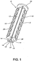
- an LED module assembly 8 includes a plurality of LEDs 10 surrounded by a structure 12.
- Each LED 10 is mounted to a surface of a printed circuit board ("PCB") 14.
- the surfaces of PCB 14 opposite the surfaces coupled to LEDs 10 are coupled to a plurality of thermal transfer interfaces ("contact pads") 16 that are in turn coupled to internal heat pipe 18.
- the structure including the connection of contact pads 16 to internal heat pipe 18 is referred to as thermal assembly 19.
- One end of thermal assembly 19 is connected to a heat pipe mating surface 20.
- the opposing end of thermal assembly 19 contains an aperture 22 designed to receive protuberance 24 located on base 26, as shown in Fig. 3 .
- LEDs 10, PCB 14, and structure 12 are collectively referred to as LED mounting structure 28.
- structure 12 substantially covers LEDs 10, PCBs 14, and thermal assembly 19 to ensure that the heat pipe is the main conduit for flow of thermal energy.
- structure 12 is a material with a low thermal conductivity. In another embodiment, structure 12 is a thermally insulating material.
- contact pad 16 and LED 10 are dimensioned to have substantially similar surface areas. In other embodiments, contact pad 16 is dimensioned to accommodate a plurality of LEDs 10, thus allowing greater flexibility in positioning LEDs 10 as needed to meet optical performance requirements.
- LED replacement is incorporated into the present invention to allow for forward compatibility of the LED lamp and to allow replacement LED module assemblies 8 to be manufactured in a manner that does not affect the optical or thermal performance of the original luminaire 32 (shown in Figs. 4-6 ) and its LED module assembly 8 as the replacement unit will have LEDs 10 in the same physical location relative to the optics, and also incorporate the same thermal mechanism (internal heat pipe 18). With higher efficacy LEDs 10 driven in a dimmed state in the same physical location, optical performance equivalent to the original luminaire 32 and LED module assembly 8 is achieved.
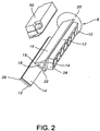
- Fig. 2 is a rotated and partially exploded view of LED module assembly 8 and including LED driver 30 that is connected to a contact pad 16 adjacent to two LED mounting structures 28.
- LEDs 10 and LED driver 30 are serviceable as a single LED module assembly 8.
- An exemplary LED driver 30 has a lifetime of 50,000 hours, which is complementary to the lifetime of LEDs 10, and thus replacement of a single LED module assembly 8 containing both LEDs 10 and LED driver 30 will minimize service costs.
- an LED module assembly 8 containing both LEDs 10 and LED driver 30 provides for forward compatibility of the LED lamp. By integrating LED driver 30 with LEDs 10 in a single replacement LED module assembly 8, LED driver 30 may be appropriately designed for future LEDs 10 with improved efficacy. Several approaches are available to enable this forward compatibility of driver and LEDs.
- LED driver 30 may be designed as a PWM dimming driver, thus allowing LEDs 10 to be dimmed to factory specified levels that match the original LED/driver combination.
- PWM dimming driver a PWM dimming driver
- LED driver 30 does not change over time, rather only the "dim level" changes. In this embodiment, there is no consideration regarding form factor changes for the luminaire/LED lamp manufacturer.
- a non-dimming LED driver 30 is redesigned periodically to accommodate efficacy improvements in LEDs 10.
- LED driver 30 may be placed in close proximity to thermal assembly 19 because LEDs 10 and the thermal conduction path are isolated. In other embodiments, the LED driver 30 may be directly attached to the thermal assembly 19.
- Fig. 3 is a fully exploded view of LED module assembly 8 and a base 26 with protuberance 24. Protuberance 24 is inserted into aperture 22 (shown in Figs. 1 and 2 ) to retain LED module assembly 8 within a housing 34 of luminaire 32 (shown in Figs. 4-6 ).
- Fig. 4 is an exploded view of an exemplary embodiment of luminaire 32, which illustrates that LED module assembly 8 may be connected to base 26 by inserting protuberance 24 into aperture 22, as shown in Figs. 1 and 2 .
- LED module assembly 8 may be inserted into housing 34 through opening 36.
- Base 26 may be securely connected to housing 34 adjacent to opening 36.
- Some embodiments utilize a housing cover 38 to cover aperture 40 in housing 34.
- External heat sink 42 may be connected to the exterior surface of housing 34 at an end opposite opening 36.
- external heat sink 42 may be connected to internal heat pipe 18 (shown in Figs. 1 and 2 ). This is done by placing an interior surface of housing 34 that is adjacent to external heat sink 42 in direct contact with heat pipe mating surface 20, which is connected to thermal assembly 19, thus reducing the number of thermal interfaces and improving heat transfer out of the luminaire enclosure.
- internal heat pipe 18 is also connected to external heat sink 42 through connection of aperture 22 (shown in Figs. 1 and 2 ) to protuberance 24 on base 26 (shown in Figs. 3 and 4 ), which is connected to housing 34 and thus to external heat sink 42.
- thermal junction 44 is created when heat pipe mating surface 20 contacts the interior surface of housing 34.
- the LED module assembly 8 may be considered to be in an engaged position relative to housing 34.
- some mechanical force is applied when the LED module assembly 8 is placed in an engaged position relative to housing 34.
- One embodiment may include the use of a spring loaded member to achieve some mechanical force between heat pipe mating surface 20 and housing 34.
- heat pipe mating surface 20 and the interior surface of housing 34 should have complementary mating surfaces that are generally flat and substantially smooth. In order to ensure easy servicing, appropriate guides should be implemented that orient and seat the heat pipe mating surface 20 relative to housing 34 without any effort required of the service personnel. The orientation feature also provides proper alignment of the LED 10 and the optical elements within the luminaire 32.
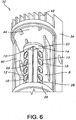
- Fig. 6 is a perspective view of one embodiment of luminaire 32, showing LED module assembly 8 in a disengaged position relative to housing 34. In this position, heat pipe mating surface 20 is not in contact with housing 34. This position allows LED module assembly 8 to be serviced without the need for substantial adjustment by service personnel.
- Fig. 7 is a perspective view of an exemplary embodiment of LED 10.
- LED reflector 46 is attached to a surface of substrate 48.
- LED lens 50 is attached to LED reflector 46 on a surface of LED reflector 46 that opposes the surface of LED reflector 46 that is attached to substrate 48.
- a plurality of electrical contact areas 52 are located on the surface of substrate 48 adjacent to LED reflector 46.
- Fig. 8 is a rotated perspective view of LED 10, which shows a plurality of electrical contact areas 52 located on the opposite surface of substrate 48 and substantially aligned with electrical contact areas 52 that are adjacent to LED reflector 46.
- the section of the surface of substrate 48 adjacent to electrical contact areas 52 and on the opposite side of substrate 48 from LED reflector 46 is referred to as thermal contact area 54.
- Figs. 9-11 show side, top, and bottom views, respectively, of LED 10.
- Fig. 12 illustrates one embodiment of a solder pad 56 that is used to connect LED 10 to PCB 14.
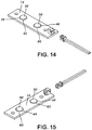
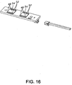
- FIG. 13-16 Another embodiment of the present invention, as illustrated in Figs. 13-16 , further improves the conduction path by placing thermal contact area 54 in direct contact with contact pad 16. thus eliminating an additional source of thermal resistance.
- This embodiment utilizes the electrical contact areas 52 on the front side of LED 10 to connect to a PCB 14 (not shown), while providing an electrically neutral thermal transfer area 54 on the back side of LED 10 to mount directly to contact pad 16. Cree XL7090 LEDs, for example, provide such electrical contact areas 52 on the front side of LED 10.
- structure 12 is first attached to PCBs 14 and LEDs 10, then coupled to thermal assembly 19 to achieve a direct interface from LED 10 to the heat transfer area.
- This embodiment has a lower thermal resistance when compared to the same LED 10 mounted to a PCB 14 that is in turn mounted to the thermal assembly 19.
- an LED "die” or “chip,” along with an encapsulant, may be directly mounted to the contact pads 16 with appropriate electrical isolation between the die and chips.
- At least one groove 58 is located on the surface of contact pads 16 substantially parallel and opposite at least one electrical contact area 52 on the bottom of LED 10. Grooves 58 are intended to prevent contact between electrical contact areas 52 and contact pad 16 so that LED 10 will not short out.
- Figs. 14 and 15 illustrate use of a plurality of LED apertures 60 to allow LED lens 50 and LED reflector 46 to extend through PCB 14 when PCB 14 is connected to electrical contact areas 52 on the surface of substrate 48 adjacent to LED reflector 46.
- Fig. 16 is a bottom view of this embodiment showing a plurality of electrical contact areas 52 and thermal contact areas 54 located on the surfaces of substrates 48 opposite the sides of substrates 48 connected to LED reflectors 46.
Landscapes
- Engineering & Computer Science (AREA)
- General Engineering & Computer Science (AREA)
- Physics & Mathematics (AREA)
- Geometry (AREA)
- Arrangement Of Elements, Cooling, Sealing, Or The Like Of Lighting Devices (AREA)
- Non-Portable Lighting Devices Or Systems Thereof (AREA)
Claims (12)
- Beleuchtungsvorrichtung, Folgendes umfassend:eine LED-Modulanordnung (8), Folgendes umfassend:eine thermische Anordnung (19), umfassend ein Wärmerohr (18) und ein Kontaktpad (16), gekoppelt an eine Außenoberfläche des Wärmerohrs (18);wenigstens eine Leuchtdiode (10), gekoppelt an das Kontaktpad (16);wobei das Wärmerohr (18) ein erstes Ende und ein zweites Ende umfasst, wobei das erste Ende des Wärmerohrs (18) an eine Wärmerohrpassoberfläche (20) gekoppelt ist,wobei die Beleuchtungsvorrichtung dadurch gekennzeichnet ist, dass sie Folgendes umfasst:wobei das erste Ende und das zweite Ende des Wärmerohrs (18) vom gekoppelten Leuchtengehäuse (34) und dem Leuchtenfuß (26) umgeben sind.ein Leuchtengehäuse (34), wobei eine Innenoberfläche des Leuchtengehäuses (34) eine Gehäusepassoberfläche umfasst, und wobei die Wärmerohrpassoberfläche (20) konfiguriert ist, die Gehäusepassoberfläche zu berühren und lösbar mit dieser in Eingriff zu treten, um eine thermische Verbindung (44) zu definieren; undeinen Leuchtenfuß (26), wobei der Leuchtenfuß (26) mit dem zweiten Ende des Wärmerohrs (18) gekoppelt ist und mit dem Leuchtengehäuse (34) gekoppelt ist,
- Beleuchtungsvorrichtung nach Anspruch 1, wobei die LED-Modulanordnung (8) ferner einen LED-Treiber (30) umfasst, der in unmittelbarer Nähe mit der thermischen Anordnung (19) verbunden ist.
- Beleuchtungsvorrichtung nach Anspruch 2, wobei der LED-Treiber (30) ein PWM-Abblendungstreiber ist.
- Beleuchtungsvorrichtung nach Anspruch 1, wobei die wenigstens eine Leuchtdiode (10) eine einzelne LED, einen LED-Chip oder ein LED-Mikroplättchen umfasst.
- Beleuchtungsvorrichtung nach Anspruch 1, wobei die wenigstens eine Leuchtdiode (10) durch Anbringen der wenigstens einen Leuchtdiode (10) an eine Leiterplatte (14), die an dem Kontaktpad (16) befestigt ist, mit dem Kontaktpad (16) gekoppelt ist.
- Beleuchtungsvorrichtung nach Anspruch 1, wobei die wenigstens eine Leuchtdiode (10) direkt auf der Oberfläche des Kontaktpads (16) angebracht ist.
- Beleuchtungsvorrichtung nach Anspruch 6, wobei das Kontaktpad (16) wenigstens einen Schlitz aufweist, der sich auf einer Oberfläche des Kontaktpads (16) im Wesentlichen parallel und gegenüber wenigstens einer elektrischen Kontaktfläche auf einer Oberfläche der wenigstens einen Leuchtdiode (10) befindet, um Kontakt zwischen dem elektrischen Kontaktbereich und dem Kontaktpad (16) zu verhindern.
- Beleuchtungsvorrichtung nach Anspruch 1, wobei das Kontaktpad (16) bemessen ist, einen im Wesentlichen ähnlichen Oberflächenbereich aufzuweisen wie eine der wenigstens einen Leuchtdiode (10).
- Beleuchtungsvorrichtung nach Anspruch 1, wobei das Kontaktpad (16) bemessen ist, mehrere Leuchtdioden (10) aufzunehmen.
- Beleuchtungsvorrichtung nach einem der Ansprüche 1 bis 5, ferner Folgendes umfassend:einen externen Kühlkörper (42) neben einem Ende des Leuchtengehäuses (34); undein an das Leuchtengehäuse (34) angebrachtes Element, das eine Position der LED-Modulanordnung (8) in Bezug auf das Leuchtengehäuse (34) anpasst und konfiguriert ist, mechanische Kraft auf die thermische Verbindung (44) aufzubringen, wenn die Wärmerohrpassoberfläche (20) die Innenoberfläche des Leuchtengehäuses (34) berührt,wobei die thermische Verbindung (44) der LED-Modulanordnung (8) zwischen der Wärmerohrpassoberfläche und der Innenoberfläche des Leuchtengehäuses (34) nahe bei dem Ende des Leuchtengehäuses (34) definiert ist.
- Beleuchtungsvorrichtung nach Anspruch 10, wobei das Element ein federbelasteter Riegel zum Einrasten und Ausrasten der LED-Modulanordnung (8) an der thermischen Verbindung (44) ist.
- Vorrichtung nach Anspruch 10, wobei die LED-Modulanordnung (8) ein Wärmerohr (18) und ein Kontaktpad (16), einstückig integriert, umfasst.
Applications Claiming Priority (2)
| Application Number | Priority Date | Filing Date | Title |
|---|---|---|---|
| US87209106P | 2006-12-01 | 2006-12-01 | |
| PCT/US2007/085875 WO2008070519A2 (en) | 2006-12-01 | 2007-11-29 | Systems and methods for thermal management of lamps and luminaires using led sources |
Publications (3)
| Publication Number | Publication Date |
|---|---|
| EP2103191A2 EP2103191A2 (de) | 2009-09-23 |
| EP2103191A4 EP2103191A4 (de) | 2013-04-10 |
| EP2103191B1 true EP2103191B1 (de) | 2016-04-27 |
Family
ID=39492993
Family Applications (1)
| Application Number | Title | Priority Date | Filing Date |
|---|---|---|---|
| EP07864872.2A Not-in-force EP2103191B1 (de) | 2006-12-01 | 2007-11-29 | Systeme und verfahren zur wärmeverwaltung von lampen und beleuchtungskörpern mit led-quellen |
Country Status (4)
| Country | Link |
|---|---|
| US (1) | US7784971B2 (de) |
| EP (1) | EP2103191B1 (de) |
| CA (1) | CA2612973C (de) |
| WO (1) | WO2008070519A2 (de) |
Families Citing this family (54)
| Publication number | Priority date | Publication date | Assignee | Title |
|---|---|---|---|---|
| US7784971B2 (en) | 2006-12-01 | 2010-08-31 | Abl Ip Holding, Llc | Systems and methods for thermal management of lamps and luminaires using LED sources |
| US7568817B2 (en) * | 2007-06-27 | 2009-08-04 | Fu Zhun Precision Industry (Shen Zhen) Co., Ltd. | LED lamp |
| US7503790B2 (en) * | 2007-07-03 | 2009-03-17 | Rockwell Automation Technologies, Inc. | Industrial automation input output module with elastomeric sealing |
| US7744250B2 (en) * | 2007-07-12 | 2010-06-29 | Fu Zhun Precision Industry (Shen Zhen) Co., Ltd. | LED lamp with a heat dissipation device |
| CN101349412A (zh) * | 2007-07-18 | 2009-01-21 | 富准精密工业(深圳)有限公司 | 发光二极管灯具 |
| US20090129087A1 (en) * | 2007-11-15 | 2009-05-21 | Starkey Carl R | Light System and Method to Thermally Manage an LED Lighting System |
| CN101435566A (zh) * | 2007-11-16 | 2009-05-20 | 富准精密工业(深圳)有限公司 | 发光二极管灯具 |
| CN101435567B (zh) * | 2007-11-16 | 2010-11-10 | 富准精密工业(深圳)有限公司 | 发光二极管灯具 |
| US8033685B2 (en) * | 2008-03-27 | 2011-10-11 | Mcgehee Michael Eugene | LED luminaire |
| US7744251B2 (en) * | 2008-04-10 | 2010-06-29 | Fu Zhun Precision Industry (Shen Zhen) Co., Ltd. | LED lamp having a sealed structure |
| US7637637B2 (en) * | 2008-04-16 | 2009-12-29 | Fu Zhun Precision Industry (Shen Zhen) Co., Ltd. | Outdoor LED lamp assembly |
| US20090268453A1 (en) * | 2008-04-24 | 2009-10-29 | King Luminarie Co., Inc. | LED baffle assembly |
| US8092032B2 (en) * | 2008-04-24 | 2012-01-10 | King Luminaire Co., Inc. | LED lighting array assembly |
| US8011809B2 (en) * | 2008-05-16 | 2011-09-06 | Yun Chang Liao | Light-emitting diode module with heat dissipating structure and lamp with light-emitting diode module |
| US7837358B2 (en) * | 2008-05-16 | 2010-11-23 | Liao yun-chang | Light-emitting diode module with heat dissipating structure |
| CN102047028A (zh) * | 2008-05-29 | 2011-05-04 | 罗姆股份有限公司 | Led灯 |
| CN101769517A (zh) * | 2008-12-27 | 2010-07-07 | 富准精密工业(深圳)有限公司 | 发光模块及应用该发光模块的发光二极管灯具 |
| US8576406B1 (en) | 2009-02-25 | 2013-11-05 | Physical Optics Corporation | Luminaire illumination system and method |
| US8419249B2 (en) * | 2009-04-15 | 2013-04-16 | Stanley Electric Co., Ltd. | Liquid-cooled LED lighting device |
| US7810968B1 (en) * | 2009-05-15 | 2010-10-12 | Koninklijke Philips Electronics N.V. | LED unit for installation in a post-top luminaire |
| DE102009058309A1 (de) * | 2009-07-09 | 2011-01-13 | Siteco Beleuchtungstechnik Gmbh | LED-Leuchteneinsatz |
| US8098433B2 (en) * | 2009-12-11 | 2012-01-17 | Solatube International, Inc. | Direct and indirect light diffusing devices and methods |
| US8568011B2 (en) | 2009-08-20 | 2013-10-29 | Solatube International, Inc. | Daylighting devices with auxiliary lighting system and light turning features |
| CN201487724U (zh) * | 2009-09-03 | 2010-05-26 | 浙江纳桑电子科技有限公司 | 一种大功率led路灯 |
| USD617493S1 (en) * | 2009-10-06 | 2010-06-08 | Hubbell Incorporated | Flow-through LED carrier for luminaire |
| CN101761806B (zh) * | 2009-12-11 | 2011-09-21 | 鸿富锦精密工业(深圳)有限公司 | 可更换透镜的led灯 |
| US20110149567A1 (en) * | 2009-12-18 | 2011-06-23 | Zhirong Lee | High Power LED Street Light Structure |
| JP5421799B2 (ja) * | 2010-01-18 | 2014-02-19 | パナソニック株式会社 | Ledユニット |
| US8601757B2 (en) | 2010-05-27 | 2013-12-10 | Solatube International, Inc. | Thermally insulating fenestration devices and methods |
| AU2010202801A1 (en) * | 2010-07-05 | 2012-01-19 | Neobulb Technologies, Inc. | Light-emitting diode illumination platform |
| US8550650B1 (en) | 2010-08-10 | 2013-10-08 | Patrick McGinty | Lighted helmet with heat pipe assembly |
| US9249952B2 (en) * | 2010-11-05 | 2016-02-02 | Cree, Inc. | Multi-configurable, high luminous output light fixture systems, devices and methods |
| USD672906S1 (en) * | 2011-02-25 | 2012-12-18 | Lg Innotek Co., Ltd. | Head of street lamp |
| US20120313547A1 (en) * | 2011-06-10 | 2012-12-13 | Honeywell International Inc. | Aircraft led landing or taxi lights with thermal management |
| US20130044476A1 (en) * | 2011-08-17 | 2013-02-21 | Eric Bretschneider | Lighting unit with heat-dissipating circuit board |
| WO2013082183A1 (en) | 2011-11-30 | 2013-06-06 | Solatube International, Inc. | Daylight collection systems and methods |
| US20130265780A1 (en) * | 2012-04-05 | 2013-10-10 | Black & Decker Inc. | Light module and light stand assembly |
| US8974077B2 (en) | 2012-07-30 | 2015-03-10 | Ultravision Technologies, Llc | Heat sink for LED light source |
| US9921397B2 (en) | 2012-12-11 | 2018-03-20 | Solatube International, Inc. | Daylight collectors with thermal control |
| US8982467B2 (en) | 2012-12-11 | 2015-03-17 | Solatube International, Inc. | High aspect ratio daylight collectors |
| US8919994B2 (en) * | 2012-12-12 | 2014-12-30 | Randal L. Wimberly | Illumination system and lamp utilizing directionalized LEDs |
| CN105849457A (zh) | 2013-10-28 | 2016-08-10 | Next照明公司 | 线性灯替代物 |
| US9195281B2 (en) | 2013-12-31 | 2015-11-24 | Ultravision Technologies, Llc | System and method for a modular multi-panel display |
| US20150192261A1 (en) * | 2014-01-08 | 2015-07-09 | Richard L. May | Linear Lighting Apparatus |
| US9835301B2 (en) * | 2014-07-01 | 2017-12-05 | Abl Ip Holding Llc | Optical systems and methods for pole luminaires |
| US9765956B2 (en) * | 2014-08-04 | 2017-09-19 | Spring City Electrical Manufacturing Company | LED luminaire light fixture for a lamppost |
| CN105371214A (zh) * | 2015-12-16 | 2016-03-02 | 广州共铸科技股份有限公司 | 一种led汽车头灯 |
| USD841849S1 (en) | 2016-10-31 | 2019-02-26 | Delta T, Llc | Handheld light assembly with battery pack |
| RU2707082C2 (ru) * | 2017-08-08 | 2019-11-22 | Денис Геннадьевич Дроздов | Светодиодный светильник (варианты) для освещения сельскохозяйственной культуры |
| RU2699013C2 (ru) * | 2017-10-27 | 2019-09-03 | Денис Геннадьевич Дроздов | Светодиодный светильник и способ освещения сельскохозяйственной культуры |
| US10344930B1 (en) * | 2018-04-30 | 2019-07-09 | Feit Electric Company, Inc. | Flame lamp |
| EP3875838B1 (de) * | 2020-03-06 | 2023-09-20 | Lumileds Holding B.V. | Beleuchtungsvorrichtung mit lichtleiter |
| RU2745978C1 (ru) * | 2020-03-15 | 2021-04-05 | Денис Геннадьевич Дроздов | Корпус-радиатор светодиодного светильника |
| US11448388B2 (en) | 2020-05-01 | 2022-09-20 | Exposure Illumination Architects, Inc. | Vertical illumination device with lamp modules having nano-optical lenses structure with light source pre-configured to uniformly illuminate horizontal areas below |
Family Cites Families (22)
| Publication number | Priority date | Publication date | Assignee | Title |
|---|---|---|---|---|
| US4081023A (en) | 1976-11-26 | 1978-03-28 | Grumman Aerospace Corporation | Heat pipes to use heat from light fixtures |
| US4411516A (en) | 1981-04-24 | 1983-10-25 | Canon Kabushiki Kaisha | Original illumination apparatus |
| WO1986002985A1 (fr) | 1984-11-15 | 1986-05-22 | Japan Traffic Management Technology Association | Unite de signalisation possedant une fonction de dissipation de chaleur |
| US4733335A (en) | 1984-12-28 | 1988-03-22 | Koito Manufacturing Co., Ltd. | Vehicular lamp |
| US6517221B1 (en) | 1999-06-18 | 2003-02-11 | Ciena Corporation | Heat pipe heat sink for cooling a laser diode |
| US6917637B2 (en) | 2001-10-12 | 2005-07-12 | Fuji Photo Film Co., Ltd. | Cooling device for laser diodes |
| US6586890B2 (en) | 2001-12-05 | 2003-07-01 | Koninklijke Philips Electronics N.V. | LED driver circuit with PWM output |
| US7048412B2 (en) | 2002-06-10 | 2006-05-23 | Lumileds Lighting U.S., Llc | Axial LED source |
| US6911915B2 (en) | 2002-09-04 | 2005-06-28 | Leotek Electronics Corporation | Compact light emitting diode retrofit lamp and method for traffic signal lights |
| EP1590996B1 (de) * | 2003-02-07 | 2010-07-14 | Panasonic Corporation | Beleuchtungseinrichtung, einen sockel verwendend, um ein flaches led-modul auf einen kühlkörper zu montieren |
| JP2004265986A (ja) | 2003-02-28 | 2004-09-24 | Citizen Electronics Co Ltd | 高輝度発光素子及びそれを用いた発光装置及び高輝度発光素子の製造方法 |
| US6910794B2 (en) * | 2003-04-25 | 2005-06-28 | Guide Corporation | Automotive lighting assembly cooling system |
| US6976769B2 (en) | 2003-06-11 | 2005-12-20 | Cool Options, Inc. | Light-emitting diode reflector assembly having a heat pipe |
| US7126290B2 (en) * | 2004-02-02 | 2006-10-24 | Radiant Power Corp. | Light dimmer for LED and incandescent lamps |
| US7246921B2 (en) | 2004-02-03 | 2007-07-24 | Illumitech, Inc. | Back-reflecting LED light source |
| US7095110B2 (en) | 2004-05-21 | 2006-08-22 | Gelcore, Llc | Light emitting diode apparatuses with heat pipes for thermal management |
| TWI263008B (en) | 2004-06-30 | 2006-10-01 | Ind Tech Res Inst | LED lamp |
| DE102005063433B4 (de) | 2004-10-29 | 2009-11-26 | Lg Display Co., Ltd. | Hintergrundbeleuchtungseinheit und Flüssigkristall-Anzeigevorrichtung |
| KR100671545B1 (ko) | 2005-07-01 | 2007-01-19 | 삼성전자주식회사 | Led 어레이 모듈 |
| US7431475B2 (en) | 2005-07-22 | 2008-10-07 | Sony Corporation | Radiator for light emitting unit, and backlight device |
| US7560742B2 (en) | 2005-11-28 | 2009-07-14 | Magna International Inc. | Semiconductor-based lighting systems and lighting system components for automotive use |
| US7784971B2 (en) | 2006-12-01 | 2010-08-31 | Abl Ip Holding, Llc | Systems and methods for thermal management of lamps and luminaires using LED sources |
-
2007
- 2007-11-29 US US11/947,463 patent/US7784971B2/en active Active
- 2007-11-29 EP EP07864872.2A patent/EP2103191B1/de not_active Not-in-force
- 2007-11-29 WO PCT/US2007/085875 patent/WO2008070519A2/en not_active Ceased
- 2007-11-30 CA CA2612973A patent/CA2612973C/en not_active Expired - Fee Related
Non-Patent Citations (1)
| Title |
|---|
| None * |
Also Published As
| Publication number | Publication date |
|---|---|
| US20080130299A1 (en) | 2008-06-05 |
| WO2008070519A2 (en) | 2008-06-12 |
| US7784971B2 (en) | 2010-08-31 |
| EP2103191A2 (de) | 2009-09-23 |
| CA2612973A1 (en) | 2008-06-01 |
| EP2103191A4 (de) | 2013-04-10 |
| WO2008070519A3 (en) | 2008-08-28 |
| CA2612973C (en) | 2013-05-14 |
Similar Documents
| Publication | Publication Date | Title |
|---|---|---|
| EP2103191B1 (de) | Systeme und verfahren zur wärmeverwaltung von lampen und beleuchtungskörpern mit led-quellen | |
| US7784969B2 (en) | LED based light engine | |
| US5785418A (en) | Thermally protected LED array | |
| US8167466B2 (en) | LED illumination device and lamp unit thereof | |
| US5782555A (en) | Heat dissipating L.E.D. traffic light | |
| US8733980B2 (en) | LED lighting modules and luminaires incorporating same | |
| US8858029B2 (en) | LED light bulbs | |
| CN101592323B (zh) | 基板及照明器具 | |
| CN102466161B (zh) | 灯装置以及照明器具 | |
| CN102829417B (zh) | 车辆用前照灯 | |
| US20070279921A1 (en) | Lighting assembly having a heat dissipating housing | |
| US20080278954A1 (en) | Mounting Assembly for Optoelectronic Devices | |
| CN203036430U (zh) | 照明器具 | |
| US20130020941A1 (en) | Semiconductor Lamp | |
| CN102159873A (zh) | 发光装置 | |
| JP2015122291A (ja) | 照明装置 | |
| JP5448253B2 (ja) | Ledランプ | |
| JP2010272497A (ja) | 電気機器 | |
| CN101553688A (zh) | 用于车辆前灯的照明单元以及车辆前灯 | |
| US20080295522A1 (en) | Thermo-energy-management of solid-state devices | |
| CN105042468B (zh) | 车辆用前照灯、散热机构、发光装置及光源固定部件 | |
| CN101769521A (zh) | 用于发光装置的散热装置及其发光装置 | |
| TW201131105A (en) | LED illumination device and illuminating apparatus employing the same | |
| US9890940B2 (en) | LED board with peripheral thermal contact | |
| JP2009245643A (ja) | 照明装置 |
Legal Events
| Date | Code | Title | Description |
|---|---|---|---|
| PUAI | Public reference made under article 153(3) epc to a published international application that has entered the european phase |
Free format text: ORIGINAL CODE: 0009012 |
|
| 17P | Request for examination filed |
Effective date: 20090630 |
|
| AK | Designated contracting states |
Kind code of ref document: A2 Designated state(s): AT BE BG CH CY CZ DE DK EE ES FI FR GB GR HU IE IS IT LI LT LU LV MC MT NL PL PT RO SE SI SK TR |
|
| DAX | Request for extension of the european patent (deleted) | ||
| A4 | Supplementary search report drawn up and despatched |
Effective date: 20130312 |
|
| RIC1 | Information provided on ipc code assigned before grant |
Ipc: H05B 41/16 20060101AFI20130306BHEP |
|
| 17Q | First examination report despatched |
Effective date: 20150116 |
|
| GRAP | Despatch of communication of intention to grant a patent |
Free format text: ORIGINAL CODE: EPIDOSNIGR1 |
|
| INTG | Intention to grant announced |
Effective date: 20151005 |
|
| GRAS | Grant fee paid |
Free format text: ORIGINAL CODE: EPIDOSNIGR3 |
|
| GRAR | Information related to intention to grant a patent recorded |
Free format text: ORIGINAL CODE: EPIDOSNIGR71 |
|
| GRAA | (expected) grant |
Free format text: ORIGINAL CODE: 0009210 |
|
| INTG | Intention to grant announced |
Effective date: 20160308 |
|
| AK | Designated contracting states |
Kind code of ref document: B1 Designated state(s): AT BE BG CH CY CZ DE DK EE ES FI FR GB GR HU IE IS IT LI LT LU LV MC MT NL PL PT RO SE SI SK TR |
|
| REG | Reference to a national code |
Ref country code: GB Ref legal event code: FG4D |
|
| REG | Reference to a national code |
Ref country code: CH Ref legal event code: EP |
|
| REG | Reference to a national code |
Ref country code: AT Ref legal event code: REF Ref document number: 796012 Country of ref document: AT Kind code of ref document: T Effective date: 20160515 |
|
| REG | Reference to a national code |
Ref country code: IE Ref legal event code: FG4D |
|
| REG | Reference to a national code |
Ref country code: DE Ref legal event code: R096 Ref document number: 602007046060 Country of ref document: DE |
|
| REG | Reference to a national code |
Ref country code: LT Ref legal event code: MG4D |
|
| REG | Reference to a national code |
Ref country code: NL Ref legal event code: MP Effective date: 20160427 |
|
| REG | Reference to a national code |
Ref country code: AT Ref legal event code: MK05 Ref document number: 796012 Country of ref document: AT Kind code of ref document: T Effective date: 20160427 |
|
| PG25 | Lapsed in a contracting state [announced via postgrant information from national office to epo] |
Ref country code: NL Free format text: LAPSE BECAUSE OF FAILURE TO SUBMIT A TRANSLATION OF THE DESCRIPTION OR TO PAY THE FEE WITHIN THE PRESCRIBED TIME-LIMIT Effective date: 20160427 |
|
| PG25 | Lapsed in a contracting state [announced via postgrant information from national office to epo] |
Ref country code: FI Free format text: LAPSE BECAUSE OF FAILURE TO SUBMIT A TRANSLATION OF THE DESCRIPTION OR TO PAY THE FEE WITHIN THE PRESCRIBED TIME-LIMIT Effective date: 20160427 Ref country code: LT Free format text: LAPSE BECAUSE OF FAILURE TO SUBMIT A TRANSLATION OF THE DESCRIPTION OR TO PAY THE FEE WITHIN THE PRESCRIBED TIME-LIMIT Effective date: 20160427 Ref country code: PL Free format text: LAPSE BECAUSE OF FAILURE TO SUBMIT A TRANSLATION OF THE DESCRIPTION OR TO PAY THE FEE WITHIN THE PRESCRIBED TIME-LIMIT Effective date: 20160427 |
|
| PG25 | Lapsed in a contracting state [announced via postgrant information from national office to epo] |
Ref country code: GR Free format text: LAPSE BECAUSE OF FAILURE TO SUBMIT A TRANSLATION OF THE DESCRIPTION OR TO PAY THE FEE WITHIN THE PRESCRIBED TIME-LIMIT Effective date: 20160728 Ref country code: AT Free format text: LAPSE BECAUSE OF FAILURE TO SUBMIT A TRANSLATION OF THE DESCRIPTION OR TO PAY THE FEE WITHIN THE PRESCRIBED TIME-LIMIT Effective date: 20160427 Ref country code: SE Free format text: LAPSE BECAUSE OF FAILURE TO SUBMIT A TRANSLATION OF THE DESCRIPTION OR TO PAY THE FEE WITHIN THE PRESCRIBED TIME-LIMIT Effective date: 20160427 Ref country code: ES Free format text: LAPSE BECAUSE OF FAILURE TO SUBMIT A TRANSLATION OF THE DESCRIPTION OR TO PAY THE FEE WITHIN THE PRESCRIBED TIME-LIMIT Effective date: 20160427 Ref country code: LV Free format text: LAPSE BECAUSE OF FAILURE TO SUBMIT A TRANSLATION OF THE DESCRIPTION OR TO PAY THE FEE WITHIN THE PRESCRIBED TIME-LIMIT Effective date: 20160427 Ref country code: PT Free format text: LAPSE BECAUSE OF FAILURE TO SUBMIT A TRANSLATION OF THE DESCRIPTION OR TO PAY THE FEE WITHIN THE PRESCRIBED TIME-LIMIT Effective date: 20160829 |
|
| RAP2 | Party data changed (patent owner data changed or rights of a patent transferred) |
Owner name: ABL IP HOLDING LLC |
|
| PG25 | Lapsed in a contracting state [announced via postgrant information from national office to epo] |
Ref country code: BE Free format text: LAPSE BECAUSE OF FAILURE TO SUBMIT A TRANSLATION OF THE DESCRIPTION OR TO PAY THE FEE WITHIN THE PRESCRIBED TIME-LIMIT Effective date: 20160427 Ref country code: IT Free format text: LAPSE BECAUSE OF FAILURE TO SUBMIT A TRANSLATION OF THE DESCRIPTION OR TO PAY THE FEE WITHIN THE PRESCRIBED TIME-LIMIT Effective date: 20160427 |
|
| REG | Reference to a national code |
Ref country code: DE Ref legal event code: R097 Ref document number: 602007046060 Country of ref document: DE |
|
| PG25 | Lapsed in a contracting state [announced via postgrant information from national office to epo] |
Ref country code: DK Free format text: LAPSE BECAUSE OF FAILURE TO SUBMIT A TRANSLATION OF THE DESCRIPTION OR TO PAY THE FEE WITHIN THE PRESCRIBED TIME-LIMIT Effective date: 20160427 Ref country code: EE Free format text: LAPSE BECAUSE OF FAILURE TO SUBMIT A TRANSLATION OF THE DESCRIPTION OR TO PAY THE FEE WITHIN THE PRESCRIBED TIME-LIMIT Effective date: 20160427 Ref country code: CZ Free format text: LAPSE BECAUSE OF FAILURE TO SUBMIT A TRANSLATION OF THE DESCRIPTION OR TO PAY THE FEE WITHIN THE PRESCRIBED TIME-LIMIT Effective date: 20160427 Ref country code: SK Free format text: LAPSE BECAUSE OF FAILURE TO SUBMIT A TRANSLATION OF THE DESCRIPTION OR TO PAY THE FEE WITHIN THE PRESCRIBED TIME-LIMIT Effective date: 20160427 Ref country code: RO Free format text: LAPSE BECAUSE OF FAILURE TO SUBMIT A TRANSLATION OF THE DESCRIPTION OR TO PAY THE FEE WITHIN THE PRESCRIBED TIME-LIMIT Effective date: 20160427 |
|
| PLBE | No opposition filed within time limit |
Free format text: ORIGINAL CODE: 0009261 |
|
| STAA | Information on the status of an ep patent application or granted ep patent |
Free format text: STATUS: NO OPPOSITION FILED WITHIN TIME LIMIT |
|
| 26N | No opposition filed |
Effective date: 20170130 |
|
| PG25 | Lapsed in a contracting state [announced via postgrant information from national office to epo] |
Ref country code: SI Free format text: LAPSE BECAUSE OF FAILURE TO SUBMIT A TRANSLATION OF THE DESCRIPTION OR TO PAY THE FEE WITHIN THE PRESCRIBED TIME-LIMIT Effective date: 20160427 |
|
| REG | Reference to a national code |
Ref country code: DE Ref legal event code: R119 Ref document number: 602007046060 Country of ref document: DE |
|
| REG | Reference to a national code |
Ref country code: CH Ref legal event code: PL |
|
| GBPC | Gb: european patent ceased through non-payment of renewal fee |
Effective date: 20161129 |
|
| PG25 | Lapsed in a contracting state [announced via postgrant information from national office to epo] |
Ref country code: LI Free format text: LAPSE BECAUSE OF NON-PAYMENT OF DUE FEES Effective date: 20161130 Ref country code: CH Free format text: LAPSE BECAUSE OF NON-PAYMENT OF DUE FEES Effective date: 20161130 |
|
| REG | Reference to a national code |
Ref country code: IE Ref legal event code: MM4A |
|
| REG | Reference to a national code |
Ref country code: FR Ref legal event code: ST Effective date: 20170731 |
|
| PG25 | Lapsed in a contracting state [announced via postgrant information from national office to epo] |
Ref country code: LU Free format text: LAPSE BECAUSE OF NON-PAYMENT OF DUE FEES Effective date: 20161130 |
|
| PG25 | Lapsed in a contracting state [announced via postgrant information from national office to epo] |
Ref country code: FR Free format text: LAPSE BECAUSE OF NON-PAYMENT OF DUE FEES Effective date: 20161130 |
|
| PG25 | Lapsed in a contracting state [announced via postgrant information from national office to epo] |
Ref country code: IE Free format text: LAPSE BECAUSE OF NON-PAYMENT OF DUE FEES Effective date: 20161129 Ref country code: DE Free format text: LAPSE BECAUSE OF NON-PAYMENT OF DUE FEES Effective date: 20170601 Ref country code: GB Free format text: LAPSE BECAUSE OF NON-PAYMENT OF DUE FEES Effective date: 20161129 |
|
| PG25 | Lapsed in a contracting state [announced via postgrant information from national office to epo] |
Ref country code: CY Free format text: LAPSE BECAUSE OF FAILURE TO SUBMIT A TRANSLATION OF THE DESCRIPTION OR TO PAY THE FEE WITHIN THE PRESCRIBED TIME-LIMIT Effective date: 20160427 Ref country code: HU Free format text: LAPSE BECAUSE OF FAILURE TO SUBMIT A TRANSLATION OF THE DESCRIPTION OR TO PAY THE FEE WITHIN THE PRESCRIBED TIME-LIMIT; INVALID AB INITIO Effective date: 20071129 |
|
| PG25 | Lapsed in a contracting state [announced via postgrant information from national office to epo] |
Ref country code: IS Free format text: LAPSE BECAUSE OF FAILURE TO SUBMIT A TRANSLATION OF THE DESCRIPTION OR TO PAY THE FEE WITHIN THE PRESCRIBED TIME-LIMIT Effective date: 20160427 Ref country code: TR Free format text: LAPSE BECAUSE OF FAILURE TO SUBMIT A TRANSLATION OF THE DESCRIPTION OR TO PAY THE FEE WITHIN THE PRESCRIBED TIME-LIMIT Effective date: 20160427 Ref country code: MC Free format text: LAPSE BECAUSE OF FAILURE TO SUBMIT A TRANSLATION OF THE DESCRIPTION OR TO PAY THE FEE WITHIN THE PRESCRIBED TIME-LIMIT Effective date: 20160427 |
|
| PG25 | Lapsed in a contracting state [announced via postgrant information from national office to epo] |
Ref country code: BG Free format text: LAPSE BECAUSE OF FAILURE TO SUBMIT A TRANSLATION OF THE DESCRIPTION OR TO PAY THE FEE WITHIN THE PRESCRIBED TIME-LIMIT Effective date: 20160427 |
|
| PG25 | Lapsed in a contracting state [announced via postgrant information from national office to epo] |
Ref country code: MT Free format text: LAPSE BECAUSE OF NON-PAYMENT OF DUE FEES Effective date: 20161129 |