EP2103206A1 - Agencement de presse et procédé de compression de fromage en forme de blocs - Google Patents
Agencement de presse et procédé de compression de fromage en forme de blocs Download PDFInfo
- Publication number
- EP2103206A1 EP2103206A1 EP09003052A EP09003052A EP2103206A1 EP 2103206 A1 EP2103206 A1 EP 2103206A1 EP 09003052 A EP09003052 A EP 09003052A EP 09003052 A EP09003052 A EP 09003052A EP 2103206 A1 EP2103206 A1 EP 2103206A1
- Authority
- EP
- European Patent Office
- Prior art keywords
- press
- support structure
- pot
- pots
- ram
- Prior art date
- Legal status (The legal status is an assumption and is not a legal conclusion. Google has not performed a legal analysis and makes no representation as to the accuracy of the status listed.)
- Withdrawn
Links
Images

Classifications
-
- A—HUMAN NECESSITIES
- A01—AGRICULTURE; FORESTRY; ANIMAL HUSBANDRY; HUNTING; TRAPPING; FISHING
- A01J—MANUFACTURE OF DAIRY PRODUCTS
- A01J25/00—Cheese-making
- A01J25/12—Forming the cheese
- A01J25/15—Presses therefor
Definitions
- the present invention relates to a press assembly for pressing cheese into block molds and to a method for pressing cheese into block molds using such a press assembly comprising a plurality of press poppy press jars, such as cheese curds, into each of which a punch is insertable on the one hand to squeeze out the whey still present in the cheese mass and on the other to give the cheese mass the desired final shape, which is predetermined by the press pots and the press punches.
- the present invention is therefore based on the object to provide a realization which makes it possible to improve the cheese production and in particular the pressing process both in economic terms and in technical terms.
- the object is achieved with a press arrangement for pressing cheese in block molds, which has the features of claim 1.
- the press arrangement at least one planar support structure, such as a support grid or a plate in which a plurality of press pots are slidably mounted along its longitudinal axis between an upper displacement position and a lower displacement position, and at least one further planar support structure such as a support grid or plate, in which a plurality of insertable into the press jaws punch are slidably mounted along its longitudinal axis between an upper displacement position and a lower displacement position.
- the individual press pots are supported by a support structure and thus indirectly communicate with each other, the individual press pots are handled together, so that it is not necessary to transport each press pot individually from a filling station for filling with cheese mass to a pressing station , Rather, the Presstöpfe can be transported together with their filling with cheese by means of the support structure of a filling station to a pressing station, whereby a reduction of the transport costs can be achieved.
- the slidable storage of both the press pots and the ram in a respective associated support structure proves to be advantageous in that thereby an individual feed of the individual ram and thus an individual pressurization of the pressure chambers defined by the Presstöpfen can be ensured.
- the slidable support of the press pots in the press pot support structure is not utilized.
- the displaceable mounting of the press pots in the press pot support structure is only utilized when a second press pot support structure and, subsequently, a second press punch support structure are applied via the first press punch support structure.
- the press pots of the second press pot support structure effectively serve as press punches which release the pressure applied to the press punches of the second press punch support structure onto the press punches of the first press punch support structure.
- the Presstöpfe are slidably mounted in the respective support structure.
- the press arrangement according to the invention makes it possible to form a plurality of parallel stacks of stacked press-stop structures and press-die support structures in such a way that, viewed in the vertical direction, a plurality of stacked press-pits alternately stacked in each stack are produced.
- each of the press pots as well as each of the press dies is slidably mounted on or in the respective associated support structure, it is thus possible to individually pressurize each of the press pot stamp column thus formed individually via the respective uppermost punch, whereby the Feed movement of the individual ram and Presstöpfe each column individually, so independent of the other columns, can be controlled. Nevertheless, the pressing process on all columns can be performed simultaneously, which leads to an advantageous increase in throughput.
- each press pot or taken from the individual Presstöpfen cheese mass of a press pot stamping column is subjected to one and the same pressure, as a result of the sliding bearing both the ram and the Presstöpfe in the respectively associated support structures propagate the force applied to the uppermost ram pressing forces evenly over the respective press pot pillar stamp down.
- the press molds which serve to receive the karseerohmasse referred to as Presstöpfe are not necessarily mean that the Presstöpfe must have a cylindrical shape. Rather, the Presstöpfe viewed in plan can be arbitrarily bounded. For example, the Presstöpfe viewed in plan view may have a triangular, rectangular, oval or a star-shaped shape with rounded tips.
- the number of press pots of the press pot support structure coincides with the number of press punches of the press punch support structure, and that the press pots and the press punches are arranged distributed in the same grid over the respective support structure.
- the press dies can be pressurized by the overlying press jars, so that ultimately the tops of the press dies form footprints for press jars disposed thereabove.
- both configurations simultaneously occur alternately in the vertical direction by arranging in a lowermost level a first press-pot support structure, above which a first press-die support structure, then a second press-stop support structure supported on the first press-die support structure, above this a second press-die support structure, etc.
- the press pot support structure can have a multiplicity of through openings in which the individual press pots are arranged.
- each press pot has two longitudinally spaced stops which are arranged to limit the displaceability of the respective press pot in cooperation with the associated through hole. The longitudinally spaced stops thus define the lower and upper maximum displacement positions of the press pots.
- a lower stop of the press pot by a press pot the circumference surrounding lower flange is formed, whereas an upper stop of the press pot is formed by a surrounding the press pot circumference collar.
- the lower flange is provided at the bottom of the press pot and the collar above the lower flange along the peripheral wall of the press pot.
- the bottom of the press pot can be a separate component connected to the peripheral wall of the same, it is provided according to a particularly preferred embodiment that the lower flange is formed by the bottom itself or by at least one edge portion of the same the peripheral wall of the press pot protrudes radially.
- the collar serving as the upper stop as a radially projecting flange along the edge defining the filling opening of the press pot.
- the press pots would extend in their lower displacement position with approximately their entire height below the respective support structure, which may be undesirable for reasons of handling.
- the press die support structure can have a multiplicity of through openings in which the individual press dies are displaceably guided.
- each ram can have two longitudinally spaced stops, which are arranged such that in cooperation with the respectively associated passage opening, the displaceability of the respective ram is limited.
- the upper stop of the press ram can be formed, for example, by an upper pressure plate of the press ram, whereas the lower stop of the press ram can be formed by a lower pressure plate of the press ram, which is spaced from the upper pressure plate by at least one spacer element.
- the spacer element of each ram is formed by at least two mutually parallel ridges, which are guided in two separate slots, which together define a respective through hole in the press die support structure.
- the spacer element in the form of two webs extending parallel to one another, which are guided in corresponding slots, each defining a passage opening, in the press-die support structure, proves to be advantageous in that thereby a tilting of the Press stamps in the press die support structure can be largely excluded.
- the abutment function of the printing plates can be realized by virtue of the fact that the passage opening assigned to each pressing ram has a smaller cross-sectional area than each of the printing plates.
- the printing plates may be dimensioned so that they protrude over the spacer in the ground plan outwardly.
- the stop function of the printing plates in that they bridge the distance between the webs serving as a spacer parallel to each other.
- the respective pressure plate comes into contact with the support structure between the slots formed therein for guiding the serving as a spacer parallel to each other extending webs, so that in this way very effectively falling out or pressing out of the ram the press die support structure can be prevented.
- the press-pot supporting structure and / or the pressing-stamp carrying structure may be a carrier grid or a plate.
- the respective passage openings for receiving the press pots or press punches can be delimited by the individual carriers forming the carrier grid which, for example, can be perpendicular to one another and spaced parallel to one another, whereby a regular carrier grid with a plurality of rectangular, preferably square, grids Through holes is formed.
- a regular carrier grid with a plurality of rectangular, preferably square, grids Through holes is formed.
- the underside supporting webs which can preferably extend along the outer boundary of / the respective support structure forming carrier grid / plate.
- the height of these support ribs and the position of the upper stop of the Presstexcellent can be coordinated according to a further embodiment of each other such that in the lowermost shift position of the Presstexcellent whose lower edge is flush with the lower edge of the support ribs.
- a plurality of projections may be provided at least on the top of the support grid or plate of the die support structure which are arranged to slidably engage the support webs of the support grid / plate stacked thereon when stacking a press pot support structure onto a die support structure.
- the protrusions provided on the upper side of at least the press-die support structure thus serve as guidance and positioning aid when stacking press-stamp and press-pot support structures.
- the press arrangement according to the invention further comprises a press frame for receiving a plurality of alternately stacked press punch and press pot support structures, which has an upper latch structure and a lower latch structure rigidly connected to the upper latch structure.
- a plurality of press units such as press spindles or piston-cylinder units are provided on the upper latch structure, which are arranged in the same grid as both the press pots and the press dies, so that the press punches and the press pots of a supported by the lower bar structure stack of press die and press pot support structures on The press units can be pressurized.
- the press arrangement is force neutral and can thus be used at any location.
- the object mentioned above is achieved by a method which has the features of claim 16.
- the method is carried out using the press assembly according to the invention, wherein a first Pressstkovtrag minimalist whose Presstöpfe were previously filled with Käserohmasse, a first Pressstkovtrag minimalist is applied such that their press punches penetrate into the underlying Presstöpfe until they get up on the Käserohmasse therein and consequently, with respect to the die support structure, are urged toward its upper translational position, preferably before the dies are pushed toward its lower translational position using the press units of the press frame.
- the method not only applies a single die support structure to a press pot support structure. Rather, it is provided according to the invention that two, three or even more press pot and press stamp support structures are alternately stacked.
- a second press pot support structure prior to the pressurization of the first die support structure, a second press pot support structure whose press pots were filled with cheese mass, and then apply a second press die support structure such that the pots of the second press pot support structure stand up on the press dies of the first press die support structure and press the dies of the second die support structure into the press jars of the second press pot support structure until they stand up on the cheese mass therein, thereby pressing the press jars of the second press pot support structure as well as the press dies of the second die support structure toward their upper translational position.
- the associated support structures are free of pressing forces and can in particular be moved vertically independently of the Presstöpfen and press punches up and down.
- the press die and press pot support structures stiffen the individual press pot pillars, allowing large press forces to be applied to the individual press pot pillars.
- this can preferably be done using the press units of the press frame, with which the press punches of the second press die support structure and over these the press jaws of the second press pot support structure and the press punches of the first press die support structure are pressed in the direction of their lower slide position.
- This can be achieved in the desired manner, an individual pressurization of the individual press pot stamp pillars, wherein the Presstöpfe be loaded within a press pot pillar or the recorded from the Presstöpfen cheese mass each with the same pressure force or is.
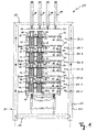
- the Fig. 1 shows a press assembly 10 according to the invention at the beginning of the press.
- the press assembly 10 comprises a press frame 11 and has an upper latch structure 12 and a lower latch structure 13, wherein the upper latch structure 12 and the lower latch structure 13 extend horizontally between two spaced-apart rows of supports 21, which are arranged perpendicular to the plane one behind the other.
- the upper latch structure 12, the lower latch structure 13 and the supports 21 thus define a frame field which serves to receive a plurality of alternately stacked mold support structures 22.1, 22.2, 22.3, 22.4 and press die support structures 24.1, 24.2, 24.3, 24.4.
- On the upper latch structure 12 eight press units 18 are arranged in the form of piston-cylinder units in a regular 4 x 2 grid, but due to the sectional view, only four press units 18 can be seen.
- the press table 17 serves to receive alternating press-stack support structures 22.1, 22.2, 22.3, 22.4 and press-stamp support structures 24.1, 24.2, 24.3, 24.4.
- press-stack support structures 22.1, 22.2, 22.3, 22.4 and press-stamp support structures 24.1, 24.2, 24.3, 24.4 To load the press table 17, it is moved out of the press frame 11 on the carrier rails 15, so that it is more easily accessible for the loading operation with the press pot and press stamp support structures 22.1, 22.2, 22.3, 22.4, 24.1, 24.2, 24.3, 24.4.
- the respectively identically constructed press-pot supporting structures 22.1, 22.2, 22.3, 22.4 each comprise a plate 26 in which eight passage openings 34 are formed in a regular 4 ⁇ 2 grid, of which, on the basis of the sectional view in FIG Fig. 1 and 2 However, only four through holes 34 are visible.
- the through holes 34 are each of circular shape and serve to receive a circular press pot 30, respectively, but for clarity in the figures, only two press pots 30 are shown.
- the through-holes 34 and / or the press pots 30 may also have a different shape.
- both the through-holes 34 and the press pots 30 may have a rectangular shape. It would also be possible that only the passage openings 34 are formed rectangular, whereas the press pots 30 are of circular shape and are slidably mounted in the rectangular, preferably square passage openings 34.
- the press pots 30 each have a cylindrical peripheral wall 40, and are closed on their underside by a circular pot bottom 38 having a larger diameter than the peripheral wall 40, whereby each of the pots 30 has a surrounding the press pot peripheral flange 46. Furthermore, the press pots 30 each have a radially projecting upper flange 44 along their filling opening. In addition, the peripheral wall 40 of each pot 30 is surrounded about halfway between the lower flange 46 and the upper flange 44 by a collar 42.
- the radial extent of both the collar 42 and the lower flange 46 and the bottom flange 46 forming pot bottom 38 is greater than the diameter of the through holes 34, so that the press pots 30 between an upper displacement position in which the lower flanges 46 at abut the plate 26 and a lower displacement position, in the collars 42 rest against the plate 26, are slidably mounted in the passage openings 34.
- the press-stamp support structures 24.1, 24.2, 24.3, 24.4 also each have a plate 28, in which eight through-openings 36 arranged in a regular 4 ⁇ 2 grid are formed.
- the ram 32 each have an upper pressure plate 48 and a lower pressure plate 50, which are held by two vertically aligned and mutually parallel webs 52 at a distance.
- the webs 52 are guided by the lateral boundaries of the through holes 36.
- each of the webs 52 could also be guided in its own slot, with the two slots assigned to a press ram 32 forming a passage opening 36.
- a stop is formed by the laterally over the webs 52 projecting portions of the pressure plates 48, 50, which prevents the press ram 32 from falling out of the through holes 36 or can be pushed out.
- the plungers 32 are thus slidable in the through holes 36 between an upper displacement position in which the lower pressure plate 50 abuts the plate 28 and a lower displacement position in which the upper pressure plate 48 abuts the plate 28 Through openings 36 stored.
- the through the height of the webs 52 defined pressing path of the ram 32 is chosen to be about as large that can be approximately halved by the ram 32 of the pressure chamber of the press pots 30.
- support webs 54 are formed on the underside of the plates 26, which preferably along the outer boundary the respective plate 26, 28 may extend.
- the height of the support webs 54 and the position of serving as an upper stop collar 42 of the Presstöpfe 30 is coordinated such that in the lower displacement position of the press pots 30 whose lower edge with the lower edge of the support webs 54 lies in a plane.
- a plurality of upstanding peg-like projections 56 are provided which are arranged such that they stack when stacking a press pot support structure 22.1, 22.2, 22.3, 22.4 on a Pressstkovtrag Decor 24.1, 24.2, 24.3, 24.4 with the support webs 54 of the overlying plate 26 slidably come into abutment, whereby both a lateral guide and a lateral reinforcement is provided when stacking the Pressstkov- and press-pot support structures 24.1, 24.2, 24.3, 24.4, 22.1, 22.2, 22.3, 22.4.
- the press units 18, the press punches 32 and the press pots 30 are each organized in a regular 4 x 2 grid.
- the 4 x 2 grid of the press units 18 and the 4 x 2 grid of the ram 32 and the 4 x 2 grid of the press pots 30 are identical, so that with the aid of a respective pressing unit 18th a press pot stamping column of a plurality of vertically alternately stacked and stacked in each Presstöpfe 30 and press die 32 can be pressurized to compress the absorbable by the individual Presstöpfen 30 cheese mass and thereby free of excess whey.
- This pressing process is discussed in more detail below.
- the press-pot support structures 22.1, 22.2, 22.3, 22.4 and the press-die support structures 24.1, 24.2, 24.3, 24.4 are alternately stacked on one another, as shown in FIG Fig. 1 is shown.
- a first press pot support structure 22.1 whose press pots 30 were previously filled to the brimful with cheese mass K, is firstly arranged on the press table 17, which has previously been moved out of the press frame 11 on the carrier rails 15.
- the press pot support structure 22 is firstly arranged on the press table 17, which has previously been moved out of the press frame 11 on the carrier rails 15.
- press pot support structure 22.1 is then placed on the press table 17 with its support webs 52, wherein no vertical displacement of the press pots 30 takes place, since its lower edge is flush with the lower edge of the support webs 54.
- the press pots 30 thus each extend approximately halfway above and below the plate 26.
- a first press-die support structure 24.1 can then be gripped and raised, for example, with a gripper in order to be deposited on or placed on the first press-pot support structure 22.1.
- the press-dies 32 hang substantially below the plate 28 thereof.
- the first press die support structure 24.1 is positioned above the first press pot support structure 22.1 such that when the first press die support structure 24.1 is lowered, the press dies 32 and their lower pressure plates 50 penetrate the press pots 30 and rise on the cheese mass K therein.
- the plate 28 of the first press die support structure 24.1 slides down the webs 52 of the press dies 32 until it rests on the upper flanges 44 of the press pots 30, resulting in complete filling of the press pots 30 of the upper shift position of the press dies 32 corresponds.
- the press-dies 32 are pushed in the direction of their upper displacement position, so that, for example, in a constellation according to FIG Fig. 1 extend to the same extent above its support structure as the press pots 30 of the first press pot support structure 22.1.
- a second Pressstopftrag Design 22.2 the Presst Adventure 30 were previously filled with cheese mass K in a filling station, for example, grabbed with a gripper and raised so that their Presst Adventure 30 rest with their collars 42 on the plate 26 and the boundary of the passage opening 34 thereof as previously described with reference to the first press pot support structure 22.1.
- the second press pot support structure 22.2 is then so positioned above the first press die support structure 24.1, that when lowering the second Pressstopftrag Design 22.2 all of its eight press pots 30 with its bottom 38 on a ram 32 and an upper pressure plate 48 of the underlying Pressstkovtrag Design 24.1 stand up.
- a second press die support structure 24.2 is subsequently stacked on the second press pot support structure 22.2 in the same manner as described above with reference to the first press die support structure 24.1.
- a third press pot support structure 22.3 is then stacked on this second press die support structure 24.2, as previously described with reference to the second press pot support structure 22.2.
- a third press die support structure 24.3, a fourth press press support structure 22.4 and a fourth press die support structure 24.4 are then stacked onto the already formed stack.
- press-pot support structures 22.1, 22.2, 22.3, 22.4 and the press-die support structures 24.1, 24.2, 24.3, 24.4 one above the other in the above-described manner one after the other on the press table 17, it is also possible to directly after the filling of the individual Press pots 30 of the press pot support structures 22.1, 22.2, 22.3, 22.4 with cheese mass, to each press frame support structures 22.1, 22.2, 22.3, 22.4 a press die support structure 24.1, 24.2, 24.3, 24.4 to stack, so that the press pot support structures 22.1, 22.2, 22.3, 22.4 and Press stamp support structures 24.1, 24.2, 24.3, 24.4 can be stacked in pairs on the press table 17 on top of each other. This also makes it possible to ensure a further rationalization of the movement processes in the cheese production.
- the pressure applied via the uppermost press dies 32 is applied via the cheese mass located in the uppermost press pot 30 and from there over the bottom of the pot 38 to the next press punch 32 and from there back to the cheese mass of the next press pot 30 and, in a corresponding manner, downward so that the cheese mass K in each press pot 30 of a press pot pillar column is subjected to the same pressure in the desired manner.
- This pressing process which is initiated by the extension of the piston rods 19 of the press units 18, can continue until the upper pressure plates 48 of the press dies 32 are in contact with the plates 28 of the press die support structures 24.1, 24.2, 24.3, 24.4, as shown in FIG of the Fig. 2 is shown, in which a further application of force on the press units 18 propagates directly through the plates 28 of the press die support structures in the underlying peripheral walls 40 of the press pots 30 and from there via the press table 17 in the support rails 15, so that no further compression of the Presstöpfen 30 recorded cheese mass K can be done more.
- the pressing operation may be terminated when a predetermined pressing time has elapsed.
- the upper pressure plates 48 of the press dies 32 do not necessarily come into contact with the plates 28 of the press die support structures 24.1, 24.2, 24.3, 24.4.
- the plates 26, 28 of the press-stop and press-stamp support structures 22.1, 22.2, 22.3, 22.4, 24.1, 24.2, 24.3, 24.4 are displaceable in the vertical direction during the entire pressing operation, so that the pressing dies 32 and Press pots 30 can move independently of these support structures or their plates 26, 28.
- the press-pot support structures 22.1, 22.2, 22.3, 22.4 and the press-die support structures 24.1, 24.2, 24.3, 24.4 serve, on the one hand, as handling aids, so that the individual press-pots 30 and press-dies 32 need not be transported individually into the press frame 11, and, secondly, as guide and Reinforcement for the individual press pot pillars, so that they can not buckle laterally during the pressing process.
Landscapes
- Life Sciences & Earth Sciences (AREA)
- Animal Husbandry (AREA)
- Environmental Sciences (AREA)
- Dairy Products (AREA)
- Press Drives And Press Lines (AREA)
Applications Claiming Priority (1)
| Application Number | Priority Date | Filing Date | Title |
|---|---|---|---|
| DE200810014977 DE102008014977A1 (de) | 2008-03-19 | 2008-03-19 | Pressenanordnung sowie Verfahren zum Pressen von Käse in Blockformen |
Publications (1)
| Publication Number | Publication Date |
|---|---|
| EP2103206A1 true EP2103206A1 (fr) | 2009-09-23 |
Family
ID=40792722
Family Applications (1)
| Application Number | Title | Priority Date | Filing Date |
|---|---|---|---|
| EP09003052A Withdrawn EP2103206A1 (fr) | 2008-03-19 | 2009-03-03 | Agencement de presse et procédé de compression de fromage en forme de blocs |
Country Status (2)
| Country | Link |
|---|---|
| EP (1) | EP2103206A1 (fr) |
| DE (1) | DE102008014977A1 (fr) |
Cited By (1)
| Publication number | Priority date | Publication date | Assignee | Title |
|---|---|---|---|---|
| RU226440U1 (ru) * | 2024-03-04 | 2024-06-04 | Общество С Ограниченной Ответственностью "Транслайн" | Пресс пневматический горизонтальный для сыра |
Citations (4)
| Publication number | Priority date | Publication date | Assignee | Title |
|---|---|---|---|---|
| DE929944C (de) * | 1953-03-17 | 1955-07-07 | Abraham Bijlenga | Kaesepresse |
| FR2555017A1 (fr) * | 1983-11-23 | 1985-05-24 | Chalon Megard Sa | Dispositif de pressage avec possibilite de retournement pour la fabrication de fromages |
| DE3541380A1 (de) * | 1985-11-22 | 1987-05-27 | Alpma Alpenland Masch | Vorrichtung zum pressen von kaesemasse fuer die herstellung von hart- od. dgl. schnittkaese sowie kaeseform zum pressen der kaesemasse |
| EP1114581A1 (fr) * | 2000-01-05 | 2001-07-11 | Seroba | Dispositif de pressage de fromages |
-
2008
- 2008-03-19 DE DE200810014977 patent/DE102008014977A1/de not_active Withdrawn
-
2009
- 2009-03-03 EP EP09003052A patent/EP2103206A1/fr not_active Withdrawn
Patent Citations (4)
| Publication number | Priority date | Publication date | Assignee | Title |
|---|---|---|---|---|
| DE929944C (de) * | 1953-03-17 | 1955-07-07 | Abraham Bijlenga | Kaesepresse |
| FR2555017A1 (fr) * | 1983-11-23 | 1985-05-24 | Chalon Megard Sa | Dispositif de pressage avec possibilite de retournement pour la fabrication de fromages |
| DE3541380A1 (de) * | 1985-11-22 | 1987-05-27 | Alpma Alpenland Masch | Vorrichtung zum pressen von kaesemasse fuer die herstellung von hart- od. dgl. schnittkaese sowie kaeseform zum pressen der kaesemasse |
| EP1114581A1 (fr) * | 2000-01-05 | 2001-07-11 | Seroba | Dispositif de pressage de fromages |
Cited By (2)
| Publication number | Priority date | Publication date | Assignee | Title |
|---|---|---|---|---|
| RU226440U1 (ru) * | 2024-03-04 | 2024-06-04 | Общество С Ограниченной Ответственностью "Транслайн" | Пресс пневматический горизонтальный для сыра |
| RU241887U1 (ru) * | 2025-06-09 | 2026-03-04 | Федеральное государственное бюджетное образовательное учреждение высшего образования "Новосибирский государственный аграрный университет" | Электромеханический вертикальный пресс для сыра |
Also Published As
| Publication number | Publication date |
|---|---|
| DE102008014977A1 (de) | 2009-09-24 |
Similar Documents
| Publication | Publication Date | Title |
|---|---|---|
| EP2616197A1 (fr) | Dispositif et procédé pour fabriquer des profilés creux au moins partiellement fermés au moyen de demi-matrices rotatives avec un temps de cycle réduit | |
| EP2233221A2 (fr) | Dispositif de poinçonnage pour une machine de poinçonnage à coupe continue d'éléments de poinçonnage métalliques | |
| AT512400B1 (de) | Biegemaschine für Drahtgittermatten | |
| EP3426387B1 (fr) | Appareil et procede pour l' installation d'une unite de garnissage structure dans une colonne d'echange de matiere | |
| DE2748462A1 (de) | Presse zur herstellung keramischer oder feuerfester fliesen oder kacheln | |
| DE69621886T2 (de) | Vorrichtung und verfahren zum herstellen von werkstücken | |
| EP0666156A1 (fr) | Procédé et dispositif pour séparer les unes des autres des tranches de blocs parallélépipèdiques en béton poreux à l'état encore plastique | |
| EP2103206A1 (fr) | Agencement de presse et procédé de compression de fromage en forme de blocs | |
| DE3002355C2 (de) | Käsepresse | |
| EP0125540B1 (fr) | Dispositif de fabrication de tubes pourvus de trous dans leur paroi | |
| EP2776237B1 (fr) | Procédé et presse de compression d'une pièce constituée d'au moins deux matériaux métalliques et/ou céramiques pulvérulents et/ou granulaires différents | |
| DE19607257C2 (de) | Hydraulische Blechformpresse | |
| WO2008011954A1 (fr) | Dispositif et procédé pour presser du fromage | |
| EP4383975B1 (fr) | Magasin de composants et installation de montage de composants sur un rail de support | |
| DE2805480A1 (de) | Vorrichtung zum ergreifen und handhaben von auf paletten angeordneten lasten | |
| DE2437703A1 (de) | Einrichtung zum herstellen von gepressten ziegelsteinen | |
| DE60108999T2 (de) | Verfahren und Vorrichtung zur Schichtenbildung von metallischen Ringen | |
| EP0806288B1 (fr) | Presse, notamment pour le pressage de pièces planes | |
| DE60117415T2 (de) | Hydraulische presse mit druckzelle mit einem aus vorgespannten lamellen bestehenden tablett | |
| DE2105890C3 (de) | Vorrichtung zum Pressen von in Formen enthaltenem Käsebruch und zum Entnehmen der gepreßten Käsemasse aus diesen | |
| DE102017108898A1 (de) | Vorrichtung und Verfahren zum Anheben oder Absenken eines Stützlagers | |
| DE3221547C2 (fr) | ||
| CH712456A2 (de) | Presse zum Herstellen von Feinschneidteilen. | |
| DE102011050971B4 (de) | Steinformmaschine mit lineargeführtem Tragelement | |
| WO2016091530A1 (fr) | Procédé pour la fabrication de tuyaux |
Legal Events
| Date | Code | Title | Description |
|---|---|---|---|
| PUAI | Public reference made under article 153(3) epc to a published international application that has entered the european phase |
Free format text: ORIGINAL CODE: 0009012 |
|
| AK | Designated contracting states |
Kind code of ref document: A1 Designated state(s): AT BE BG CH CY CZ DE DK EE ES FI FR GB GR HR HU IE IS IT LI LT LU LV MC MK MT NL NO PL PT RO SE SI SK TR |
|
| AX | Request for extension of the european patent |
Extension state: AL BA RS |
|
| AKX | Designation fees paid | ||
| STAA | Information on the status of an ep patent application or granted ep patent |
Free format text: STATUS: THE APPLICATION IS DEEMED TO BE WITHDRAWN |
|
| 18D | Application deemed to be withdrawn |
Effective date: 20100324 |
|
| REG | Reference to a national code |
Ref country code: DE Ref legal event code: 8566 |