EP2103242A2 - Ensemble de brosse et aspirateur l'utilisant - Google Patents
Ensemble de brosse et aspirateur l'utilisant Download PDFInfo
- Publication number
- EP2103242A2 EP2103242A2 EP20080163772 EP08163772A EP2103242A2 EP 2103242 A2 EP2103242 A2 EP 2103242A2 EP 20080163772 EP20080163772 EP 20080163772 EP 08163772 A EP08163772 A EP 08163772A EP 2103242 A2 EP2103242 A2 EP 2103242A2
- Authority
- EP
- European Patent Office
- Prior art keywords
- brush
- cleaned
- vacuum cleaner
- supporting bracket
- fixing
- Prior art date
- Legal status (The legal status is an assumption and is not a legal conclusion. Google has not performed a legal analysis and makes no representation as to the accuracy of the status listed.)
- Granted
Links
Images

Classifications
-
- A—HUMAN NECESSITIES
- A47—FURNITURE; DOMESTIC ARTICLES OR APPLIANCES; COFFEE MILLS; SPICE MILLS; SUCTION CLEANERS IN GENERAL
- A47L—DOMESTIC WASHING OR CLEANING; SUCTION CLEANERS IN GENERAL
- A47L9/00—Details or accessories of suction cleaners, e.g. mechanical means for controlling the suction or for effecting pulsating action; Storing devices specially adapted to suction cleaners or parts thereof; Carrying-vehicles specially adapted for suction cleaners
- A47L9/02—Nozzles
- A47L9/06—Nozzles with fixed, e.g. adjustably fixed brushes or the like
-
- A—HUMAN NECESSITIES
- A47—FURNITURE; DOMESTIC ARTICLES OR APPLIANCES; COFFEE MILLS; SPICE MILLS; SUCTION CLEANERS IN GENERAL
- A47L—DOMESTIC WASHING OR CLEANING; SUCTION CLEANERS IN GENERAL
- A47L9/00—Details or accessories of suction cleaners, e.g. mechanical means for controlling the suction or for effecting pulsating action; Storing devices specially adapted to suction cleaners or parts thereof; Carrying-vehicles specially adapted for suction cleaners
- A47L9/02—Nozzles
- A47L9/04—Nozzles with driven brushes or agitators
-
- A—HUMAN NECESSITIES
- A47—FURNITURE; DOMESTIC ARTICLES OR APPLIANCES; COFFEE MILLS; SPICE MILLS; SUCTION CLEANERS IN GENERAL
- A47L—DOMESTIC WASHING OR CLEANING; SUCTION CLEANERS IN GENERAL
- A47L9/00—Details or accessories of suction cleaners, e.g. mechanical means for controlling the suction or for effecting pulsating action; Storing devices specially adapted to suction cleaners or parts thereof; Carrying-vehicles specially adapted for suction cleaners
- A47L9/02—Nozzles
- A47L9/06—Nozzles with fixed, e.g. adjustably fixed brushes or the like
- A47L9/0633—Nozzles with fixed, e.g. adjustably fixed brushes or the like with retractable brushes, combs, lips or pads
- A47L9/064—Nozzles with fixed, e.g. adjustably fixed brushes or the like with retractable brushes, combs, lips or pads actuating means therefor
- A47L9/0653—Nozzles with fixed, e.g. adjustably fixed brushes or the like with retractable brushes, combs, lips or pads actuating means therefor with mechanical actuation, e.g. using a lever
-
- A—HUMAN NECESSITIES
- A47—FURNITURE; DOMESTIC ARTICLES OR APPLIANCES; COFFEE MILLS; SPICE MILLS; SUCTION CLEANERS IN GENERAL
- A47L—DOMESTIC WASHING OR CLEANING; SUCTION CLEANERS IN GENERAL
- A47L9/00—Details or accessories of suction cleaners, e.g. mechanical means for controlling the suction or for effecting pulsating action; Storing devices specially adapted to suction cleaners or parts thereof; Carrying-vehicles specially adapted for suction cleaners
- A47L9/02—Nozzles
- A47L9/06—Nozzles with fixed, e.g. adjustably fixed brushes or the like
- A47L9/066—Nozzles with fixed, e.g. adjustably fixed brushes or the like with adjustably mounted brushes, combs, lips or pads; Height adjustment of nozzle or dust loosening tools
Definitions
- the present invention relates to a vacuum cleaner, and more particularly to a brush assembly for suctioning in dust-laden air from a surface being cleaned and for separating the dust from the air.
- a vacuum cleaner generally draws in dust-laden air from a surface being cleaned, separates the dust from the air, and collects the separated dust, using a suction force generated in the vacuum cleaner.
- Conventional vacuum cleaners include a brush assembly positioned opposite the surface being cleaned. The brush assembly strikes the surface being cleaned to dissipate dust on the surface into the air so that dust-laden air can be drawn into the vacuum cleaner via a suction force.
- the brush assembly often includes a rotating brush having bristles protruding from the periphery thereof. The brush removes dust from the surface being cleaned by causing the bristles to strike the surface.
- the intensity of the contact of the brush on a surface such as a wooden floor, is more powerful than on an uneven surface, such as a carpeted floor. The brush cannot satisfactorily remove hair and other long materials from a carpet, which reduces the efficiency of the vacuum cleaner.
- Exemplary embodiments of the present invention address at least the above problems and/or disadvantages and other problems and/or disadvantages not described above.
- the present invention is not required to overcome the disadvantages described above, and embodiments within the scope of the present invention may not overcome any of the problems described above.
- a brush assembly for a vacuum cleaner comprising: a brush body comprising a suction inlet; a main brush which is rotatably coupled to the brush body through the suction inlet to face a surface being cleaned; and a secondary brush which is rotatably mounted on the brush body to rotate between at least two positions including a first position, in which the secondary brush contacts the surface being cleaned, and a second position, in which the secondary brush does not contact the surface being cleaned.
- the secondary brush may include a rake member comprising a plurality of teeth which are positioned along the suction inlet; and at least one supporting bracket which rotatably connect both ends of the rake member to the brush body.
- the rake member moves between the at least two positions of the secondary brush.
- a vacuum cleaner including a cleaner body which generates a suction force; and a brush assembly which removes dust from a surface being cleaned by drawing dust-laden air into the cleaner body
- the brush assembly may include a brush body including a suction inlet; a main brush which is rotatably coupled to the brush body at the suction inlet to face the surface; and a secondary brush which is rotatably mounted on the brush body to rotate between at least two positions including a first position, in which the secondary brush contacts the surface being cleaned, and a second position, in which the secondary brush does not contact the surface being cleaned.
- FIG. 1 is a perspective view illustrating a vacuum cleaner according to an exemplary embodiment of the present invention.
- a vacuum cleaner 1 of the present invention includes a cleaner body 10 and a brush assembly 100.
- the brush assembly 100 is capable of changing the type of brush in use according to the condition of a surface being cleaned, and a vacuum cleaner having the same.
- the cleaner body 10 houses a suction force generation mechanism (not shown), such as a suction motor, to draw in dust-laden air, and a dust separating means to separate dust from the air and to collect the separated dust.
- a suction force generation mechanism such as a suction motor
- a dust separating means to separate dust from the air and to collect the separated dust.
- the brush assembly 100 travels along a surface, and removes dust from the surface.
- the brush assembly 100 is in fluid communication with the cleaner body 10 through an extension pipe 11, and suctions in dust which is removed from the surface being cleaned using a suction force generated in the cleaner body 10.
- the dust suctioned in by the brush assembly 100 is drawn into the cleaner body 10 through the extension pipe 11, and is separated from the air by the dust separating means.
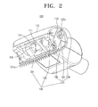
- the brush assembly 100 includes a brush body 110, a main brush 120, and a secondary brush 130.
- the brush body 110 includes a suction inlet 111 which faces a surface being cleaned, and one surface of which is open. Both ends of the main brush 120 are rotatably supported on inner surfaces of the brush body 110, and are external to the suction inlet 111. Bristles 121 are positioned on a periphery of the main brush 120. The bristles 121 of the main brush 120 rotate while contacting the surface being cleaned, and thereby remove dust from the surface.
- bristles 121 are positioned on the periphery of the main brush 120 in this exemplary embodiment of the present invention, as an alternative blades may be formed on the periphery of the main brush 120.
- the secondary brush 130 may be rotatably mounted on the brush body 110 so that either the secondary brush 130 or the main brush 120 is in operation.
- the secondary brush 130 is coupled to the brush body 110 so that the secondary brush 130 can rotate between a first position, in which it contacts the surface being cleaned, and a second position, in which it does not contact the surface being cleaned.
- the secondary brush 130 may include a rake member 131, at least one supporting bracket 132, and a stopper 133.
- the rake member 131 rakes the surface, such as a carpet, in a manner similar to a brush in order to remove dust from the surface.
- a plurality of teeth 131 a are formed on the periphery of the rake member 131 along the suction inlet 111 and facing the surface being cleaned.
- the plurality of teeth 131 a may be formed of rubber.
- the supporting bracket 132 rotatably supports the rake member 131 on the brush body 110.
- the supporting bracket 132 is formed integrally with both ends of the rake member 131, is housed in a recess 112, and is inserted into the ends of the brush body 110 so as to be rotatable in a direction indicated by arrow A1 or A2.
- the stopper 133 prevents the rake member 131 from rotating when not intended by a user, and includes first and second fixing grooves 134 and 135, respectively, and a fixing member 136.
- the first and second fixing grooves 134 and 135 are formed on a portion adjacent to the recess 112 of the brush body 110 to correspond to the first and second positions, respectively, of the rake member 131.
- the first fixing groove 134 corresponds to the first position of the rake member 131
- the second fixing groove 135 corresponds to second position of the rake member 131.
- the rake member 131 rotates between two positions, that is, the first position in which the surface is cleaned, and the second position, in which the surface is not cleaned, and the corresponding two fixing grooves 134 and 135 are provided.
- the rake member 131 can be situated in five positions, for example, three positions in which the surface is cleaned and two positions in which the surface is not cleaned, and five fixing grooves are provided to correspond to the number of the positions.
- the present invention is not limited to the above arrangements.
- the fixing member 136 is slidably mounted on the supporting bracket 132 to be fitted into the first or second fixing groove 134 or 135, and to prevent rotation of the supporting bracket 132.
- the fixing member 136 is mounted on the supporting bracket 132 in order to be slid between a first location, in which the fixing member 135 is inserted into the first or second fixing groove 134 or 135 in a direction indicated by arrow B1 or B2, and a second location, in which the fixing member 135 is not inserted into the first or second fixing groove 134 or 135.
- a guide groove 132a may be formed on each supporting bracket 132 to guide the fixing member 136 in the direction indicated by arrow B1 or B2.
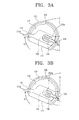
- the rake member 131 When cleaning a flat surface, such as a wooden floor, the rake member 131 may be rotated in the direction indicated by arrow A1 about the brush body 110, as shown in FIGS. 3A and 3B , so that only the main brush 120 is used to remove the dust from the surface.
- the fixing member 136 slides in the direction indicated by arrow B1, rotates to be opposite the second fixing groove 135, and slides in the direction indicated by arrow B2, in order to be fixedly inserted into the second fixing groove 135.
- the fixing member 136 prevents the supporting bracket 132 from further movement, and the rake member 131 remains at the second position, where it is not used to clean a surface. Accordingly, the rake member 131 does not interfere with the operation of the main brush 120.
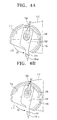
- the rake member 131 When cleaning an uneven surface, such as a carpeted floor, the rake member 131 may be rotated in the direction indicated by arrow A2, as shown in FIGS. 4A and 4B , to be placed at the first position so as to be in contact with the surface being cleaned.
- the fixing member 136 is detached from the second fixing groove 135 by being slid in the direction indicated by arrow B1, rotates together with the rake member 131 in the direction indicated by arrow A2, and is fixedly inserted into the first fixing groove 134 by being slid in the direction indicated by arrow B2.
- the rake member 131 is fixed at the first position and unintentional rotation of the rake member 131 is prevented.
- the dust removed from the surface being cleaned by the main brush 120 or the secondary brush having the rake member 131 is drawn into the cleaner body 10 connected through the extension pipe 11, and is separated by a separating means (not shown).
- the main brush which always contacts the surface being cleaned
- the secondary brush which selectively contacts the surface being cleaned
Landscapes
- Engineering & Computer Science (AREA)
- Mechanical Engineering (AREA)
- Nozzles For Electric Vacuum Cleaners (AREA)
Applications Claiming Priority (1)
| Application Number | Priority Date | Filing Date | Title |
|---|---|---|---|
| KR1020080025613A KR101473793B1 (ko) | 2008-03-19 | 2008-03-19 | 브러시 조립체 및 이를 포함하는 진공청소기 |
Publications (3)
| Publication Number | Publication Date |
|---|---|
| EP2103242A2 true EP2103242A2 (fr) | 2009-09-23 |
| EP2103242A3 EP2103242A3 (fr) | 2013-06-05 |
| EP2103242B1 EP2103242B1 (fr) | 2015-11-04 |
Family
ID=40801991
Family Applications (1)
| Application Number | Title | Priority Date | Filing Date |
|---|---|---|---|
| EP08163772.0A Ceased EP2103242B1 (fr) | 2008-03-19 | 2008-09-05 | Ensemble de brosse et aspirateur l'utilisant |
Country Status (5)
| Country | Link |
|---|---|
| US (1) | US8196258B2 (fr) |
| EP (1) | EP2103242B1 (fr) |
| KR (1) | KR101473793B1 (fr) |
| CN (1) | CN101536891B (fr) |
| AU (1) | AU2008207344B2 (fr) |
Cited By (1)
| Publication number | Priority date | Publication date | Assignee | Title |
|---|---|---|---|---|
| WO2015044399A1 (fr) * | 2013-09-30 | 2015-04-02 | Koninklijke Philips N.V. | Buse pour aspirateur |
Families Citing this family (8)
| Publication number | Priority date | Publication date | Assignee | Title |
|---|---|---|---|---|
| USD621109S1 (en) * | 2009-03-19 | 2010-08-03 | Bissell Homecare, Inc. | Upholstery cleaning tool |
| USD621110S1 (en) * | 2009-05-22 | 2010-08-03 | Eden Denise C | Nozzle with integrated handle |
| USD621111S1 (en) * | 2010-02-12 | 2010-08-03 | Samsung Electronics Co., Ltd. | Brush for vacuum cleaner |
| CN201668348U (zh) * | 2010-04-19 | 2010-12-15 | 苏志平 | 风动地刷机构 |
| CN106491046B (zh) * | 2016-12-12 | 2019-09-06 | 江苏美的清洁电器股份有限公司 | 用于吸尘器的附件刷和吸尘器 |
| KR102438130B1 (ko) * | 2017-08-28 | 2022-08-31 | 삼성전자주식회사 | 공기청정기 |
| WO2020264183A1 (fr) | 2019-06-26 | 2020-12-30 | Milwaukee Electric Tool Corporation | Outils à vide |
| CN114100100B (zh) * | 2021-11-25 | 2022-07-12 | 惠州市恒吉五金制品有限公司 | 一种便于携带的发球机 |
Citations (1)
| Publication number | Priority date | Publication date | Assignee | Title |
|---|---|---|---|---|
| US20070143954A1 (en) | 2005-03-09 | 2007-06-28 | Bissell Homecare, Inc. | Vacuum Cleaner with Hair Collection Element |
Family Cites Families (15)
| Publication number | Priority date | Publication date | Assignee | Title |
|---|---|---|---|---|
| US3825972A (en) | 1973-04-23 | 1974-07-30 | Scott & Fetzer Co | Shag rug fluffer |
| US4143441A (en) * | 1977-01-10 | 1979-03-13 | National Union Electric Corporation | Vacuum cleaner nozzle |
| GB2072495B (en) | 1980-03-25 | 1983-11-30 | Wessel H | Vacuum cleaner nozzles |
| DE4036634A1 (de) * | 1990-11-16 | 1992-05-21 | Siemens Ag | Staubsaugermundstueck |
| JPH0614853A (ja) * | 1992-06-30 | 1994-01-25 | Hitachi Ltd | 電気掃除機の吸口体 |
| US5652996A (en) * | 1995-12-01 | 1997-08-05 | The Hoover Company | Hand held cleaner with swiveling nozzle |
| CA2192882C (fr) * | 1996-01-23 | 2002-04-16 | Shigenori Hato | Outil de succion pour aspirateur electrique |
| FR2799360B1 (fr) * | 1999-10-12 | 2001-12-28 | Millet Marius | Suceur d'aspirateur a corps flottant |
| JP3858217B2 (ja) * | 2000-11-29 | 2006-12-13 | 三菱電機株式会社 | 電気掃除機 |
| KR100556811B1 (ko) * | 2004-06-12 | 2006-03-10 | 엘지전자 주식회사 | 진공청소기의 흡입헤드 |
| JP4621544B2 (ja) * | 2005-06-08 | 2011-01-26 | 株式会社東芝 | 吸込口体及びこれを備える電気掃除機 |
| JP2007252644A (ja) * | 2006-03-23 | 2007-10-04 | Toshiba Corp | 電気掃除機の吸込口体および電気掃除機 |
| KR100757383B1 (ko) | 2006-10-11 | 2007-09-11 | 삼성광주전자 주식회사 | 진공청소기의 노즐조립체 |
| KR20080033048A (ko) | 2006-10-11 | 2008-04-16 | 삼성광주전자 주식회사 | 보조브러시유닛을 구비한 노즐조립체 |
| JP2008104627A (ja) * | 2006-10-25 | 2008-05-08 | Matsushita Electric Ind Co Ltd | 掃除機用吸込具及び電気掃除機 |
-
2008
- 2008-03-19 KR KR1020080025613A patent/KR101473793B1/ko not_active Expired - Fee Related
- 2008-07-31 US US12/183,176 patent/US8196258B2/en active Active
- 2008-08-15 AU AU2008207344A patent/AU2008207344B2/en not_active Ceased
- 2008-09-04 CN CN2008102137605A patent/CN101536891B/zh not_active Expired - Fee Related
- 2008-09-05 EP EP08163772.0A patent/EP2103242B1/fr not_active Ceased
Patent Citations (1)
| Publication number | Priority date | Publication date | Assignee | Title |
|---|---|---|---|---|
| US20070143954A1 (en) | 2005-03-09 | 2007-06-28 | Bissell Homecare, Inc. | Vacuum Cleaner with Hair Collection Element |
Cited By (3)
| Publication number | Priority date | Publication date | Assignee | Title |
|---|---|---|---|---|
| WO2015044399A1 (fr) * | 2013-09-30 | 2015-04-02 | Koninklijke Philips N.V. | Buse pour aspirateur |
| US9572466B2 (en) | 2013-09-30 | 2017-02-21 | Koninklijke Philips N.V. | Nozzle for a vacuum cleaner |
| RU2666092C2 (ru) * | 2013-09-30 | 2018-09-05 | Конинклейке Филипс Н.В. | Насадка для пылесоса |
Also Published As
| Publication number | Publication date |
|---|---|
| AU2008207344A1 (en) | 2009-10-08 |
| KR101473793B1 (ko) | 2014-12-17 |
| EP2103242B1 (fr) | 2015-11-04 |
| CN101536891A (zh) | 2009-09-23 |
| US8196258B2 (en) | 2012-06-12 |
| KR20090100176A (ko) | 2009-09-23 |
| EP2103242A3 (fr) | 2013-06-05 |
| CN101536891B (zh) | 2013-05-15 |
| AU2008207344B2 (en) | 2014-02-06 |
| US20090235483A1 (en) | 2009-09-24 |
Similar Documents
| Publication | Publication Date | Title |
|---|---|---|
| EP2103242B1 (fr) | Ensemble de brosse et aspirateur l'utilisant | |
| US7716784B2 (en) | Suction port assembly and vacuum cleaner having the same | |
| EP3231344B1 (fr) | Corps d'aspiration pour un aspirateur vertical | |
| US20100205768A1 (en) | Brush assembly of vacuum cleaner | |
| CN101150975A (zh) | 多功能真空吸尘器 | |
| JPH07299015A (ja) | 真空掃除機の回転型常用吸入口 | |
| CN100998482A (zh) | 用于真空吸尘器的吸尘刷 | |
| KR101331719B1 (ko) | 청소 키트 및 이를 포함하는 자동 청소기 | |
| JP2012235867A (ja) | 電気掃除機用吸込具 | |
| KR100445807B1 (ko) | 업라이트형 진공청소기의 흡입 호스 조립체 | |
| US11197594B2 (en) | Cleaner | |
| JP2004121879A (ja) | 電気掃除機 | |
| JP6623114B2 (ja) | 電気掃除機の吸込具及びこれを備える電気掃除機 | |
| KR102725309B1 (ko) | 진공 청소기 노즐 | |
| WO2024157496A1 (fr) | Accessoire pour aspirateur électrique | |
| KR101192869B1 (ko) | 진공 청소기용 흡입구체 | |
| JP2017018413A (ja) | 電気掃除機 | |
| US8166609B2 (en) | Suction nozzle and vacuum cleaner having the same | |
| KR970003567B1 (ko) | 진공청소기의 보조청소기 | |
| JP2013094211A (ja) | 電気掃除機用吸込具およびそれを用いた電気掃除機 | |
| KR20050061734A (ko) | 진공청소기의 복합형 노즐 | |
| JP2010162081A (ja) | 電気掃除機 | |
| JPH1043098A (ja) | 電気掃除機の床用吸込口 | |
| JPS6219139A (ja) | 電気掃除機用床ノズル | |
| HK1072706A1 (zh) | 電動清掃機 |
Legal Events
| Date | Code | Title | Description |
|---|---|---|---|
| PUAI | Public reference made under article 153(3) epc to a published international application that has entered the european phase |
Free format text: ORIGINAL CODE: 0009012 |
|
| AK | Designated contracting states |
Kind code of ref document: A2 Designated state(s): AT BE BG CH CY CZ DE DK EE ES FI FR GB GR HR HU IE IS IT LI LT LU LV MC MT NL NO PL PT RO SE SI SK TR |
|
| AX | Request for extension of the european patent |
Extension state: AL BA MK RS |
|
| RAP1 | Party data changed (applicant data changed or rights of an application transferred) |
Owner name: SAMSUNG ELECTRONICS CO., LTD. |
|
| RAP1 | Party data changed (applicant data changed or rights of an application transferred) |
Owner name: SAMSUNG ELECTRONICS CO., LTD. |
|
| PUAL | Search report despatched |
Free format text: ORIGINAL CODE: 0009013 |
|
| AK | Designated contracting states |
Kind code of ref document: A3 Designated state(s): AT BE BG CH CY CZ DE DK EE ES FI FR GB GR HR HU IE IS IT LI LT LU LV MC MT NL NO PL PT RO SE SI SK TR |
|
| AX | Request for extension of the european patent |
Extension state: AL BA MK RS |
|
| RIC1 | Information provided on ipc code assigned before grant |
Ipc: A47L 9/04 20060101ALI20130426BHEP Ipc: A47L 9/06 20060101AFI20130426BHEP |
|
| 17P | Request for examination filed |
Effective date: 20131202 |
|
| RBV | Designated contracting states (corrected) |
Designated state(s): AT BE BG CH CY CZ DE DK EE ES FI FR GB GR HR HU IE IS IT LI LT LU LV MC MT NL NO PL PT RO SE SI SK TR |
|
| AKX | Designation fees paid |
Designated state(s): DE FR GB |
|
| 17Q | First examination report despatched |
Effective date: 20140922 |
|
| GRAP | Despatch of communication of intention to grant a patent |
Free format text: ORIGINAL CODE: EPIDOSNIGR1 |
|
| INTG | Intention to grant announced |
Effective date: 20150522 |
|
| GRAS | Grant fee paid |
Free format text: ORIGINAL CODE: EPIDOSNIGR3 |
|
| GRAA | (expected) grant |
Free format text: ORIGINAL CODE: 0009210 |
|
| AK | Designated contracting states |
Kind code of ref document: B1 Designated state(s): DE FR GB |
|
| REG | Reference to a national code |
Ref country code: GB Ref legal event code: FG4D |
|
| REG | Reference to a national code |
Ref country code: DE Ref legal event code: R096 Ref document number: 602008040964 Country of ref document: DE |
|
| REG | Reference to a national code |
Ref country code: DE Ref legal event code: R097 Ref document number: 602008040964 Country of ref document: DE |
|
| REG | Reference to a national code |
Ref country code: FR Ref legal event code: PLFP Year of fee payment: 9 |
|
| PLBE | No opposition filed within time limit |
Free format text: ORIGINAL CODE: 0009261 |
|
| STAA | Information on the status of an ep patent application or granted ep patent |
Free format text: STATUS: NO OPPOSITION FILED WITHIN TIME LIMIT |
|
| 26N | No opposition filed |
Effective date: 20160805 |
|
| REG | Reference to a national code |
Ref country code: FR Ref legal event code: PLFP Year of fee payment: 10 |
|
| REG | Reference to a national code |
Ref country code: FR Ref legal event code: PLFP Year of fee payment: 11 |
|
| PGFP | Annual fee paid to national office [announced via postgrant information from national office to epo] |
Ref country code: FR Payment date: 20180822 Year of fee payment: 11 Ref country code: DE Payment date: 20180820 Year of fee payment: 11 |
|
| PGFP | Annual fee paid to national office [announced via postgrant information from national office to epo] |
Ref country code: GB Payment date: 20180822 Year of fee payment: 11 |
|
| REG | Reference to a national code |
Ref country code: DE Ref legal event code: R119 Ref document number: 602008040964 Country of ref document: DE |
|
| PG25 | Lapsed in a contracting state [announced via postgrant information from national office to epo] |
Ref country code: DE Free format text: LAPSE BECAUSE OF NON-PAYMENT OF DUE FEES Effective date: 20200401 |
|
| GBPC | Gb: european patent ceased through non-payment of renewal fee |
Effective date: 20190905 |
|
| PG25 | Lapsed in a contracting state [announced via postgrant information from national office to epo] |
Ref country code: FR Free format text: LAPSE BECAUSE OF NON-PAYMENT OF DUE FEES Effective date: 20190930 Ref country code: GB Free format text: LAPSE BECAUSE OF NON-PAYMENT OF DUE FEES Effective date: 20190905 |