EP2103261B1 - Implantat - Google Patents
Implantat Download PDFInfo
- Publication number
- EP2103261B1 EP2103261B1 EP20090155739 EP09155739A EP2103261B1 EP 2103261 B1 EP2103261 B1 EP 2103261B1 EP 20090155739 EP20090155739 EP 20090155739 EP 09155739 A EP09155739 A EP 09155739A EP 2103261 B1 EP2103261 B1 EP 2103261B1
- Authority
- EP
- European Patent Office
- Prior art keywords
- piece
- frustoconical
- locking
- bearing
- optionally
- Prior art date
- Legal status (The legal status is an assumption and is not a legal conclusion. Google has not performed a legal analysis and makes no representation as to the accuracy of the status listed.)
- Not-in-force
Links
- 210000003484 anatomy Anatomy 0.000 claims description 40
- 208000034991 Hiatal Hernia Diseases 0.000 claims description 19
- 206010020028 Hiatus hernia Diseases 0.000 claims description 19
- -1 polyoxymethylene Polymers 0.000 claims description 15
- 229920000642 polymer Polymers 0.000 claims description 11
- 210000002784 stomach Anatomy 0.000 claims description 11
- 238000002513 implantation Methods 0.000 claims description 9
- 229930040373 Paraformaldehyde Natural products 0.000 claims description 8
- 239000004696 Poly ether ether ketone Substances 0.000 claims description 8
- 239000004698 Polyethylene Substances 0.000 claims description 8
- 239000004743 Polypropylene Substances 0.000 claims description 8
- 229920002530 polyetherether ketone Polymers 0.000 claims description 8
- 229920000139 polyethylene terephthalate Polymers 0.000 claims description 8
- 229920006324 polyoxymethylene Polymers 0.000 claims description 8
- 210000003815 abdominal wall Anatomy 0.000 claims description 5
- 210000002216 heart Anatomy 0.000 claims description 5
- 210000003734 kidney Anatomy 0.000 claims description 5
- 210000004185 liver Anatomy 0.000 claims description 5
- 210000004072 lung Anatomy 0.000 claims description 5
- 229920000573 polyethylene Polymers 0.000 claims description 5
- 229920001155 polypropylene Polymers 0.000 claims description 5
- 210000004291 uterus Anatomy 0.000 claims description 5
- 230000003387 muscular Effects 0.000 claims description 4
- 239000013013 elastic material Substances 0.000 claims description 3
- 229920001296 polysiloxane Polymers 0.000 claims description 3
- 230000001012 protector Effects 0.000 description 32
- 206010019909 Hernia Diseases 0.000 description 18
- 210000003238 esophagus Anatomy 0.000 description 18
- 230000000903 blocking effect Effects 0.000 description 14
- 238000000034 method Methods 0.000 description 10
- 210000003205 muscle Anatomy 0.000 description 9
- 238000010008 shearing Methods 0.000 description 7
- 239000005020 polyethylene terephthalate Substances 0.000 description 6
- 238000002357 laparoscopic surgery Methods 0.000 description 5
- 239000012528 membrane Substances 0.000 description 4
- 208000021302 gastroesophageal reflux disease Diseases 0.000 description 3
- 230000002787 reinforcement Effects 0.000 description 3
- 238000001356 surgical procedure Methods 0.000 description 3
- 206010000060 Abdominal distension Diseases 0.000 description 2
- 240000008042 Zea mays Species 0.000 description 2
- 210000000683 abdominal cavity Anatomy 0.000 description 2
- 230000003187 abdominal effect Effects 0.000 description 2
- 238000004026 adhesive bonding Methods 0.000 description 2
- 210000000038 chest Anatomy 0.000 description 2
- 210000001072 colon Anatomy 0.000 description 2
- 210000003236 esophagogastric junction Anatomy 0.000 description 2
- 239000007943 implant Substances 0.000 description 2
- 238000002350 laparotomy Methods 0.000 description 2
- 238000010992 reflux Methods 0.000 description 2
- 210000000115 thoracic cavity Anatomy 0.000 description 2
- 206010061218 Inflammation Diseases 0.000 description 1
- 208000031481 Pathologic Constriction Diseases 0.000 description 1
- 230000001464 adherent effect Effects 0.000 description 1
- 230000004075 alteration Effects 0.000 description 1
- 210000000709 aorta Anatomy 0.000 description 1
- 210000000988 bone and bone Anatomy 0.000 description 1
- 210000002318 cardia Anatomy 0.000 description 1
- 239000011248 coating agent Substances 0.000 description 1
- 238000000576 coating method Methods 0.000 description 1
- 238000009826 distribution Methods 0.000 description 1
- 230000000694 effects Effects 0.000 description 1
- 230000003628 erosive effect Effects 0.000 description 1
- 230000002349 favourable effect Effects 0.000 description 1
- 230000004054 inflammatory process Effects 0.000 description 1
- 210000003041 ligament Anatomy 0.000 description 1
- 230000007774 longterm Effects 0.000 description 1
- 210000000111 lower esophageal sphincter Anatomy 0.000 description 1
- 230000007257 malfunction Effects 0.000 description 1
- 239000000463 material Substances 0.000 description 1
- 238000002844 melting Methods 0.000 description 1
- 230000008018 melting Effects 0.000 description 1
- 210000001087 myotubule Anatomy 0.000 description 1
- 230000007170 pathology Effects 0.000 description 1
- 230000035515 penetration Effects 0.000 description 1
- 230000002572 peristaltic effect Effects 0.000 description 1
- 239000004810 polytetrafluoroethylene Substances 0.000 description 1
- 229920001343 polytetrafluoroethylene Polymers 0.000 description 1
- 230000002980 postoperative effect Effects 0.000 description 1
- 238000004321 preservation Methods 0.000 description 1
- 230000000750 progressive effect Effects 0.000 description 1
- 230000010349 pulsation Effects 0.000 description 1
- 238000002271 resection Methods 0.000 description 1
- 230000000241 respiratory effect Effects 0.000 description 1
- 230000000717 retained effect Effects 0.000 description 1
- 238000007493 shaping process Methods 0.000 description 1
- 239000002904 solvent Substances 0.000 description 1
- 210000000952 spleen Anatomy 0.000 description 1
- 230000036262 stenosis Effects 0.000 description 1
- 208000037804 stenosis Diseases 0.000 description 1
- 238000005728 strengthening Methods 0.000 description 1
- 239000000126 substance Substances 0.000 description 1
- 230000001360 synchronised effect Effects 0.000 description 1
- 210000001186 vagus nerve Anatomy 0.000 description 1
- 230000002792 vascular Effects 0.000 description 1
- 210000001835 viscera Anatomy 0.000 description 1
- 238000003466 welding Methods 0.000 description 1
Images




Classifications
-
- A—HUMAN NECESSITIES
- A61—MEDICAL OR VETERINARY SCIENCE; HYGIENE
- A61B—DIAGNOSIS; SURGERY; IDENTIFICATION
- A61B17/00—Surgical instruments, devices or methods
- A61B17/04—Surgical instruments, devices or methods for suturing wounds; Holders or packages for needles or suture materials
- A61B17/0401—Suture anchors, buttons or pledgets, i.e. means for attaching sutures to bone, cartilage or soft tissue; Instruments for applying or removing suture anchors
-
- A—HUMAN NECESSITIES
- A61—MEDICAL OR VETERINARY SCIENCE; HYGIENE
- A61B—DIAGNOSIS; SURGERY; IDENTIFICATION
- A61B17/00—Surgical instruments, devices or methods
- A61B17/04—Surgical instruments, devices or methods for suturing wounds; Holders or packages for needles or suture materials
- A61B17/0487—Suture clamps, clips or locks, e.g. for replacing suture knots; Instruments for applying or removing suture clamps, clips or locks
-
- A—HUMAN NECESSITIES
- A61—MEDICAL OR VETERINARY SCIENCE; HYGIENE
- A61B—DIAGNOSIS; SURGERY; IDENTIFICATION
- A61B17/00—Surgical instruments, devices or methods
- A61B17/04—Surgical instruments, devices or methods for suturing wounds; Holders or packages for needles or suture materials
- A61B17/0469—Suturing instruments for use in minimally invasive surgery, e.g. endoscopic surgery
-
- A—HUMAN NECESSITIES
- A61—MEDICAL OR VETERINARY SCIENCE; HYGIENE
- A61B—DIAGNOSIS; SURGERY; IDENTIFICATION
- A61B17/00—Surgical instruments, devices or methods
- A61B17/04—Surgical instruments, devices or methods for suturing wounds; Holders or packages for needles or suture materials
- A61B17/0401—Suture anchors, buttons or pledgets, i.e. means for attaching sutures to bone, cartilage or soft tissue; Instruments for applying or removing suture anchors
- A61B2017/0404—Buttons
-
- A—HUMAN NECESSITIES
- A61—MEDICAL OR VETERINARY SCIENCE; HYGIENE
- A61B—DIAGNOSIS; SURGERY; IDENTIFICATION
- A61B17/00—Surgical instruments, devices or methods
- A61B17/04—Surgical instruments, devices or methods for suturing wounds; Holders or packages for needles or suture materials
- A61B17/0487—Suture clamps, clips or locks, e.g. for replacing suture knots; Instruments for applying or removing suture clamps, clips or locks
- A61B2017/0488—Instruments for applying suture clamps, clips or locks
-
- A—HUMAN NECESSITIES
- A61—MEDICAL OR VETERINARY SCIENCE; HYGIENE
- A61B—DIAGNOSIS; SURGERY; IDENTIFICATION
- A61B17/00—Surgical instruments, devices or methods
- A61B17/04—Surgical instruments, devices or methods for suturing wounds; Holders or packages for needles or suture materials
- A61B17/06—Needles ; Sutures; Needle-suture combinations; Holders or packages for needles or suture materials
- A61B17/06166—Sutures
- A61B2017/06176—Sutures with protrusions, e.g. barbs
Definitions
- the present invention relates to the technical field of implantable devices for the approximation of fragile anatomical structures, such as the diaphragm pillars in the treatment of hiatal hernia.
- the hiatal opening is crossed by the distal segment of the esophagus accompanied by anterior and posterior vagus nerves.
- the junction between the stomach and the esophagus (cardia) is normally located below the diaphragm.
- the diaphragmatic muscle separates the abdominal cavity and the thoracic cavity. It has three orifices that allow the passage of the vena cava, the aorta and the esophagus.
- the passage opening of the esophagus is called the hiatal orifice. It is formed essentially by the right diaphragmatic pounder, with a smaller contribution from the left pillar.
- the right pillar originates from the anterior longitudinal vertebral ligament that covers the lumbar vertebrae.
- a hiatal hernia is caused by an alteration of the anatomy of the hiatal orifice.
- Anatomical structures normally confined in the abdominal cavity then pass through said deformed orifice and are found in the intrathoracic position.
- the treatment of a hiatal hernia involves the reduction of the hernia, that is to say the repositioning of the herniated viscera below the diaphragm, and the plasty of the enlarged hiatal opening.
- the plasty of the hiatal opening consists of the recalibration of the hiatal opening around the esophagus, without mechanically compressing the esophagus while ensuring a satisfactory closure which must prevent recurrence of the hernia.
- This repair is applied to a muscular structure (pillars of the diaphragm) that does not have the resistance of a fascial structure and is solicited by intra-abdominal (positive) and thoracic (negative) pressure variations.
- the location of the hiatal (posterior) orifice increases the difficulty of the technical gesture.
- a first technique of plasty of hiatal hernias is to suture with nonabsorbable sutures the pillars of the diaphragm, forward and / or back of the esophagus.
- Tabs usually made of PTFE, can be inserted between the suture and the diaphragm pillars to avoid shearing the muscle structures, this suture technique is then called suture supported.
- This suture technique is then called suture supported.
- This first technique performed by laparoscopy reports recurrence rates up to 42% higher than the recurrence rates observed in conventional surgery, that is to say by laparotomy.
- There is no randomized study comparing simple suture and supported suture The difference in rates of recurrence between open surgery and laparoscopic surgery suggests the existence of technical difficulties specific to laparoscopic surgery.
- a second technique involves strengthening the suture of the pillars by covering it with a prosthesis that partially or totally surrounds the esophagus.
- the prosthesis is invariably close to the wall of the esophagus.
- a study carried out over a short period of 6 months demonstrates a recurrence rate of 9% after reinforcement with a prosthesis compared to 24% for simple suture.
- Direct contact between the prosthesis and the wall of the esophagus can cause either a fibrous inflammatory reaction that causes stenosis of the esophagus, or progressive erosion of the esophageal wall with penetration of the prosthesis into the lumen of the esophagus.
- These complications require surgical revision up to resection of the esophagus.
- the probability of observing these complications is increased by the fact that prosthesis-esophageal contact is dynamic, between the respiratory movements of the diaphragm and the peristaltic movements of the esophagus, which are not synchronized.
- a third technique is to have a prosthesis on the hiatal orifice without tension, that is to say without prior suture of the pillars. No long-term follow-up has been reported to date on this latter technique.
- FR 2,889,441 A1 describes a reinforcement prosthesis used for the implementation of the second and third techniques.
- This prosthesis has a flange shape in the center of which is placed the esophagus.
- the preamble of claim 1 is based on the document WO 2005/016176 .
- the present invention relates to an implantable device overcoming the aforementioned problems for the approximation of fragile anatomical structures, including muscle structures such as the abdominal wall, the pillars of the diaphragm in the treatment of hiatal hernia, heart, stomach or the uterus, or parenchymal structures such as the kidneys, the liver and the lungs, comprising at least a first elongate member for bringing together at least two of said anatomical structures having along its length a first support piece, fixed or fixable in a given position of said first element, at least one locking piece fixed at a given distance D of said first support piece in said position, and a second support piece which is able to slide along the length of said elongate element in so that, during implantation, said locking piece is forced through said second support piece and abuts against said second support piece, the first and second support members delimiting between them a space having at least one dimension D less than or equal to D and adapted to receive and enclose said anatomical structures.
- the second bearing piece has a first orifice allowing passage of the first elongate member and comprises a first hollow frustoconical piece having cutouts forming lateral fins and having a central recess which extends said first passage opening, the outlet diameter of the recess of the first frustoconical part being smaller than the bulk of said locking piece so that the forced passage of said locking piece through the second support piece is obtained thanks to the radial deformation fins.
- the first frustoconical piece is provided with a protector having a width of the order of the height of said frustoconical piece, optionally increased by all or part of the height of said locking piece, and able to be arranged in operation on the first frustoconical piece, and possibly said locking piece, so as to cover at least said lateral cutouts.
- fragile anatomical structure is meant any anatomical structure with the exception of the bones, and in particular the muscular and parenchymal structures.
- the first port allows the second support piece to slide freely along the length of said first elongate member.
- the first frustoconical piece preferably extends from the outer face of said second support piece so that it retains a substantially flat inner face so as not to shear the anatomical structures.
- the protector prevents the first elongate element, and possibly the locking piece, from passing through one of the lateral cutouts during the force passage of said locking piece causing the deformation of said fins or once the implanted device, and not come into contact with the outer surface of the anatomical structures to avoid any risk of shearing and interfere with the handling of the device by the practitioner.
- the locking piece in particular when it has a thinned or pointed end, is preferably covered by said protector to avoid perforating neighboring anatomical structures.
- the Applicant has observed that, without a protector, if the first elongate element and possibly the locking piece pass through a lateral cut and come into contact with the pillar receiving the second support piece, the pillar is sheared transversely by the latter and the bringing together of the pillars operated by the device is then zero .
- the protector thus prevents any shearing of the pillars of the diaphragm and allows that the approach of the pillars operated by the device according to the invention is perfectly stable.
- the elongate member traverses said anatomical structures, which are held between the first and second support pieces.
- Said anatomical structures, for example the pillars are sandwiched between the support pieces locked and distant at a determined distance D less than or equal to D so that the practitioner knows precisely the distance by which he has brought said anatomical structures together thus increasing. the precision of the operative technique.
- the device In the case of treatment of the hiatal hernia, the device once implanted has no external edges likely to come into contact with the esophageal wall.
- the device is easy to implement unlike the prostheses and sutures used in the state of the art which reduces the post-operative risk of recurrence.
- said device being compact can be easily implanted by laparoscopy.
- the left and right pillars abut against the inner faces of the first and second support pieces and are retained in their narrowed position between them. It is of course possible to implant the device according to the present invention by laparotomy.
- the first support piece and the one or more locking pieces are fixed or fixable along the length of said elongated element by any means mechanical or chemical known from the state of the art: clipping, gluing, ultrasonic or high frequency welding ..., or by making a knot on itself of said elongate member acting as a locking piece or rear stop for said first piece of support.
- first and second support members have at least one substantially planar inner face, preferably said inner face has a generally elliptical shape.
- the flat inner faces of the first and second support members are pressed against the anatomical structures, so that they can not shear the fibrous muscle structure of the latter when it comes to muscles, particularly the pillars of the diaphragm.
- the first support piece has a substantially flat overall shape.
- the device comprises a second elongate member for approximating said anatomical structures, the first support piece being fixed or fixable in a given position of said second element, and at least one locking piece fixed on the length of said second element to a given distance D of said first support piece in said position, the second support piece being able to slide along the length of said second elongate element so that, during implantation, said locking piece is forced through said second support piece and abuts against said second support piece.
- the second support piece is able to slide both on the first elongate element and on the second elongate element.
- the second element also passes through said anatomical structures so that it can not shear their outer surfaces.
- the choice of the number of elongated element is a function of the reinforcement to be made to the plasty of the esophageal hiatus and the type of hiatal hernia.
- the first, and possibly the second, elongated element comprises several successive locking pieces, preferably having a height of the same order, at predetermined distances D of said first support piece, preferably the distance D is included in the range [10; 25] mm.
- the first, and possibly the second, elongated element preferably comprises four locking pieces, the first being at a distance D preferably of the order of 10 mm from the first support piece, the following locking pieces being spaced the each other preferably of the order of 5 mm from said first blocking part.
- the locking pieces are as much a reference for the practitioner to block the second support piece and precisely determine the distance D 'according to which the anatomical structures are close together, which was not possible with the sutures and orthoses used in the treatment. state of the art, particularly for the treatment of hiatal hernia.
- the locking pieces disposed on the first and second elongate members are preferably at equal distances from said first support piece so that the practitioner forces two locking pieces at a time through the second support piece so as to form a space defined between the first and second support members having at least one dimension D 'substantially constant.
- the height of a locking piece corresponds to the length of a portion of first or second elongate element in which said piece is fixed.
- the locking pieces are identical and have a height of the same order.
- the second support piece has a second orifice allowing the passage of said second elongate element.
- the second port allows the second support piece to slide freely along the length of said second elongate member.
- the second support piece comprises a second hollow frustoconical part having cutouts forming lateral fins and having a central recess which extends the second passage opening.
- the outlet diameter of the recess of said second frustoconical piece is smaller than the size of the blocking piece, so that the force passage of the blocking piece through the second piece of support is obtained thanks to the radial deformation of the fins.
- the second hollow frustoconical piece preferably extends from the outer face of said second support piece so that it retains a substantially flat inner face so as not to shear the anatomical structures.
- the first, and possibly the second, hollow frustoconical part has an internal shoulder in its end portion forming a housing adapted to receive all or part of the height of a locking piece.
- the height of the locking piece is housed inside the first, or second, frustoconical piece and in the central recess.
- the lateral cutouts are thus partly, or totally according to the depth of the shoulder, closed by the locking piece so that the elongated member can pass through said fins and shear surrounding anatomical structures.
- said second frustoconical piece is provided with a protector having a width of the order of the height of said second frustoconical piece, optionally increased by all or part of the height of one of the locking pieces, and capable of to be disposed in operation on said second frustoconical piece and possibly said locking piece, so as to cover at least said lateral cutouts.
- the second support piece preferably comprises two frustoconical parts as described above and two of said protectors, each being able to be arranged in operation on the frustoconical parts.
- the width of the protector is determined so that it covers both the side cuts and all or part of the height of the piece blocking selected.
- the width of the protector corresponds to the height of said frustoconical piece plus the height of the locking piece minus the depth of said shoulder. This arrangement allows the locking piece, in particular when it has a thinned or even pointed end, to be covered by said protector to avoid perforating neighboring anatomical structures.
- This protector prevents the second elongate element, and possibly the locking piece, from passing through one of the lateral cutouts and does not come into contact with the outer surface of the anatomical structures in order to avoid any risk of shearing.
- the protector of the first hollow frustoconical part, and possibly the protector of the second hollow frustoconical part consists of a strip made of an elastic material, preferably based on silicone.
- the protector may be held on the first frustoconical piece simply by its elastic force or glued, preferably according to its base on the outer face of the second support piece corresponding to its non-oriented face in operation towards the anatomical structures to be brought together.
- the protector although pressed against the frustoconical piece so as to cover at least said lateral cutouts of the latter, is sufficiently elastic in order to allow the lateral fins to deform radially when the blocking piece is forced through the hole. passage opening.
- the protector can thus be selected independently of the other parts of the device (first and second support parts, first and second frustoconical parts), in particular by its width, as a function of the height of the frustoconical part and / or the height of the the blocking part.
- the first, and possibly the second, elongate element is a monofilament, a braid or a rigid cable of small diameter, preferably of the order of 1.7 mm.
- the first, and possibly the second, elongated element has a rigid end and curve allowing its introduction in said anatomical structures, in particular opposite said first support piece.
- Said end may be formed from the first or second elongate element itself by coating or impregnating an implantable polymer and then shaping, or by melting the polymer or polymers forming said first or second element using a solvent of these. Said end may also be formed by providing on the free end a molded curved and rigid molded piece.
- the locking piece or pieces have a generally frustoconical shape.
- the first and second support members, the one or more locking pieces, the first hollow frustoconical piece, possibly the second hollow frustoconical piece, the protector of the first hollow frustoconical, possibly the protector of the second hollow frustoconical piece. are molded, preferably in a polymer selected from the following polymers: PEEK (polyetheretherketone), POM (polyoxymethylene), PET (polyethylene terephthalate), PP (polypropylene), PE (polyethylene).
- the protector being in this case rigid, is in the form of a cylinder extending from the face of the second non-oriented support piece in operation towards the anatomical structures to be brought together.
- the protector covers at least the lateral cutouts of the hollow frustoconical part without coming into direct contact with said frustoconical piece and thus its fins so as to provide a free space, delimited between said frustoconical piece and said protector, in which said fins can deform radially during the passage of force of the locking piece.
- the invention relates to a second aspect an assembly for the approximation of fragile anatomical structures, including muscle structures such as the abdominal wall, the pillars of the diaphragm in the treatment of hiatal hernia, heart, stomach or uterus or structures parenchymatics such as kidneys, liver and lungs comprising an implantable device according to one of the embodiments described above and an implantation kit comprising in particular a traction member and a pusher.
- the invention relates to a third aspect, the use of one or more implantable devices according to one of the embodiments described above, for the approximation of muscle structures such as the abdominal wall, the diaphragm, the heart, the stomach or the uterus.
- the invention relates in a fourth aspect, the use of one or more implantable devices according to one of the embodiments described above, for the approximation of parenchymal structures such as the kidneys, liver and lungs.
- the implantable device 1 shown in FIG. Figure 1A is intended for the treatment of hiatal hernia. It comprises an elongate element of approximation 2, which comprises along its length a first support piece 3, fixed and ending one of the ends 2a of said elongate member 2, and four locking pieces 4,5,6,7 successive.
- the first 4, second 5, third 6 and fourth 7 locking pieces are respectively at distances D1, D2, D3, D4 of said first support piece 3.
- D1, D2, D3, D4 are respectively equal to 10 mm, 15 mm, 20 mm and 25 mm.
- the locking pieces 4,5,6,7 respectively have a height h4, h5, h6, h7 of the same order, in this specific example of the order of 5 mm.
- the locking pieces 4,5,6,7 have a generally frustoconical shape whose smallest base is oriented on said elongated element 2 in a direction opposite to the first support piece 3.
- the first support piece 3 and the blocking pieces 4,5,6,7 are fixed along the length of said elongated element 2 by any means known from the state of the art, for example by gluing.
- the device 1 comprises a second support piece 8, represented in FIG. Figure 1B , having an orifice 8a allowing the passage of said elongated element 2.
- the first 3 and second 8 support pieces have their inner surfaces 3a, 8b substantially flat and have, viewed along their inner faces 3a, 8b, a general shape of ellipse .
- the first support piece 3 has a generally flat shape.
- the second support piece 8 comprises a hollow frustoconical piece 9 extending from its outer face 8c.
- the frustoconical piece 9 has cutouts 10 forming lateral fins 11 and having a central recess 9a which extends the orifice of passage 8a.
- the outlet diameter of the recess 9a of said frustoconical piece 9 is smaller than the size of the locking pieces 4,5,6,7.
- the elongate element 2 has a rigid and curved end 2b opposite said first support piece 3.
- the device 1 also comprises a protector in the form of a strip 12 in an elastic and implantable material, of preferably based on silicone, having a width l1 of the order of the height h1 of said frustoconical piece 9, preferably of the order of the height h1 added to the height h4, h5, h6, h7 of one of blocking parts 4,5,6,7.
- Said band 12 is arranged in operation on the frustoconical piece 9 so as to cover not only the lateral cutouts 10, but also the locking piece 4,5,6,7 to protect the anatomical structures close to any perforations due to the thinned end, generally in the shape of a tip, of the locking piece 4,5,6,7.
- the figure 2 is a schematic representation of a hiatal hernia 13 highlighting the rise by the esophageal hiatus 13 of a portion 14a of the stomach 14 following a distention between the pillars 15,16 of the diaphragm.
- the device 1 is preferably implanted by laparoscopy.
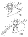
- the base of the esophagus 17 is removed by means of a lake 18 kept under tension and being in the form of a cord to clear the pillars 15,16.
- the elongated element 2 is introduced through the pillars 15,16, substantially at their centers, from its curved end 2b serving as means for introducing said elongated element 2 as shown in FIG. figure 4 .
- the elongate element 2 is thus introduced until the first support piece 3 comes into abutment and abuts against the pillar 16.
- the flat inner face 3a of the first support piece 3 comes into contact with the outer surface of said pillar 16 as shown in figure 5 .
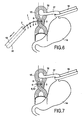
- the practitioner puts in tension said elongate member 2 by means of a traction member 19 passed through the inner conduit of a pusher 20 and attached to its curved end 2b.
- the second support piece 8 can be easily threaded from the curved and rigid end 2b and then pushed through said inner conduit by means of a piston actuated by the practitioner.
- the practitioner then has the second support piece 8 against the second pillar 15 by actuating both the traction member 19 putting in tension said elongated member 2 and the piston for forcing the second piece 8 on each blocking piece to the locking piece predetermined by the practitioner according to the degree of distension of the pillars 15,16.
- the second support piece 8 is inserted so that its flat inner face 8b comes into contact with the second pillar 15.
- the fins 11 of the frustoconical piece 9 are deformed radially for its passage, in the example illustrated the fourth locking piece 4 abuts against the second support piece 8.
- the practitioner adjusts the bringing together of the two pillars 15, 16 by means of the locking pieces which it forces one by one through said second support piece 8.
- the second piece 8 was forced over the four locking pieces 4,5,6,7.
- the space delimited between said support pieces 3.8 thus has at least one dimension D less than 10 mm capable of receiving and gripping the two pillars 15, 16 of the diaphragm.
- the practitioner cuts the elongate element 2 flush with the fourth locking piece 4 abuts against the second support piece 8 and removes the slender member portion 2 cut and the pusher 20 and the lake 18.
- the band 12 is pre-positioned on the frustoconical piece 9 before implantation.
- the elastic band 12 prevents during the passage of force blocking parts 4,5,6,7, causing the deformation of the fins, that the elongated element 2 passes through one of the side cuts and does not come shear the pillars 15,16 and / or interfere with the handling of the device 1 by the practitioner.
- the device 1 thus implanted is perfectly maintained in tension by said locking member 4, which also maintains the inner planar faces 3a, 8b against the fibrous abutments 15, 16.
- the device 1 has no part capable of shearing the outer surface of the pillars 15,16.
- the pillars 15,16 are kept close together durably.
- the frustoconical piece 9 'shown in FIGS. figures 10 and 11 is a variant of the frustoconical piece 9 described above. Only the elements of the frustoconical piece 9 'which differs from the part 9 are renumbered.
- the frustoconical piece 9 ' has an internal shoulder 9'a having a depth h1' in its end portion 9b forming a housing adapted to receive a portion of the height h4, h5, h6, h7 of one of the locking pieces 4,5,6,7.
- the width l1 'of the band 12' is of the order of the height h1 of the frustoconical piece 9 'plus the height h4, h5, h6, h7 minus the depth h1' of the internal shoulder 9a so in operation (as represented in part by the figure 10 ), the band 12 'covers both the lateral cutouts 10 and the locking piece portion emerging from the shoulder 9a.
- the elongated element 2 is not likely to shear neighboring anatomical structures passing through one of the cuts, and the thinned or sharp end of the blocking piece is not likely to perforate said structures.
- the first 3 and second 8 bearing parts, including the frustoconical parts 9, 9 'and the blocking parts 4,5,6,7 are molded, preferably in a polymer chosen from the following polymers: PEEK (polyetheretherketone), POM (polyoxymethylene), PET (polyethylene terephthalate), PP (polypropylene), PE (polyethylene).
- PEEK polyetheretherketone
- POM polyoxymethylene
- PET polyethylene terephthalate
- PP polypropylene
- PE polyethylene
- the protector 12 "shown in figure 13 is a variant of the protector or strip 12 'shown in FIG. figure 10 . Only the elements of the frustoconical piece 9 'that differs from the piece 9 are renumbered to the figure 13 .
- This protector 12 " is molded at the same time as the second support piece 8 and the first frustoconical piece 9 ', preferably in a polymer chosen from the following polymers: PEEK (polyetheretherketone), POM (polyoxymethylene), PET (polyethylene terephthalate) , PP (polypropylene), PE (polyethylene) .
- the protector 12 ", being in this case rigid, is in the form of a cylinder extending from the face 8c of the second support piece 8.
- the protector 12 "covers the lateral cutouts 10 of the hollow frustoconical piece 9 'without coming into direct contact with said frustoconical piece 9' and therefore its fins 11 so as to provide a free space, delimited between said frustoconical piece 9 'and said protector 12', in which said fins 11 can deform radially during the passage of force in the blocking part 4,5,6,7.
- the device 1 'shown in FIG. figure 11 differs from the device 1 in that it comprises two elongate elements 21,22.
- the first support piece 23 has a flat inner face 23a sufficient to be fixed in two different fastening zones 23b, 23c at the ends 21a, 22a of the first 21 and second 22 elements.
- Each elongated element 21, 22 has four locking pieces, preferably arranged as described above.
- the second support piece 24, at the figure 12 comprises a first 24a and a second 24b passage orifices to be slidably mounted at the same time respectively on the first 21 and the second 22 elongate elements.
- Opposite the first support piece 23, the free ends 21b, 22b of the elements 21, 22 are rigid and curved.
- the second support piece 24 comprises two frustoconical parts 25,26 projecting from its outer face 24c identical to the frustoconical piece 9 of the device 1 and each having in operation a band of the type of the strip 12.
- the practitioner successively passes the first element 21 and the second element 22 through the pillars of the diaphragm until the first support piece 23 abuts against a first pillar. Then he puts the second support piece 24 on the first 21 and second 22 elongate elements with the first 24a and second 24b through holes. Each of the locking pieces disposed along the length of the first 21 and second 22 elements is forced through the first 24a and second 24b through holes.
- the practitioner blocks the second support piece 24 with two pieces blocking devices arranged substantially at a distance of the same order from the first support 23.
- the second elongate element 22, like the first elongate element 21, does not shear the pillars and reinforces the clamping pressure exerted by the device 1 'and in particular the first 23 and second 24 support pieces.
- the device 1 'allows the use of support pieces 23,24 having greater bearing surfaces than those of the parts 3,8 of the device 1, and better balance the distribution of the tensions exerted by the first 21 and second 22 elongate elements between said parts 23,24.
- the frustoconical parts 25,26 each comprise a protector in the form of a tube in an adherent elastic material equivalent to the protector 12 of the device 1.
Landscapes
- Health & Medical Sciences (AREA)
- Surgery (AREA)
- Life Sciences & Earth Sciences (AREA)
- Biomedical Technology (AREA)
- Nuclear Medicine, Radiotherapy & Molecular Imaging (AREA)
- Engineering & Computer Science (AREA)
- Heart & Thoracic Surgery (AREA)
- Medical Informatics (AREA)
- Molecular Biology (AREA)
- Animal Behavior & Ethology (AREA)
- General Health & Medical Sciences (AREA)
- Public Health (AREA)
- Veterinary Medicine (AREA)
- Rheumatology (AREA)
- Prostheses (AREA)
Claims (14)
- Implantierbare Vorrichtung (1,1') für die Annäherung fragiler anatomischer Strukturen, insbesondere von Muskelstrukturen, wie der Bauchwandung, der Zwerchfellpfeiler bei der Behandlung des Zwerchfellbruchs, des Herzens, des Magens oder der Gebärmutter, oder von parenchymatösen Strukturen, wie den Nieren, der Leber und den Lungen, umfassend wenigstens ein erstes langgestrecktes Element (2, 21) zur Annäherung von wenigstens zwei der anatomischen Strukturen (15, 16), das über seine Länge ein erstes Anlageteil (3), welches in einer gegebenen Position des ersten Elements (2, 21) fest oder fixierbar ist, wenigstens ein Blockierungsteil (4, 5, 6, 7), welches in einem gegebenen Abstand D (D1, D2, D3, D4) von dem ersten Anlageteil (3) in der genannten Position festgelegt ist, sowie ein zweites Anlageteil (8) umfaßt, das eine den Durchgang des ersten langgestreckten Elements (2, 21) ermöglichende erste Öffnung (8a, 24a) aufweist und das über die Länge des ersten langgestreckten Elements (2, 21) derart verschieblich ist, daß während des Implantierens das Blockierungsteil (4, 5, 6, 7) durch das zweite Anlageteil (8) gedrückt wird und an dem zweiten Anlageteil (8) in Anschlag gelangt, wobei das erste Anlageteil (3) und das zweite Anlageteil (8) zwischen sich einen Raum begrenzen, der wenigstens eine Abmessung D' aufweist, die kleiner als oder gleich D ist, und geeignet ist, die anatomischen Strukturen (15, 16) aufzunehmen und festzuklemmen, dadurch gekennzeichnet, daß das zweite Anlageteil (8, 24) ein erstes kegelstumpfförmiges Hohlteil (9, 9', 25) umfaßt, das Seitenflügel (11) bildende Ausschnitte (10) sowie eine mittlere Aussparung (9a) aufweist, die die erste Durchgangsöffnung (8a, 24a, 25a) fortsetzt, wobei der Austrittsdurchmesser der Aussparung (9a) des ersten kegelstumpfförmigen Teils (9, 9', 25) kleiner als der Platzbedarf des Blockierungsteils (4, 5, 6, 7) ist, so daß das Hindurchdrücken des Blockierungsteils (4, 5, 6, 7) durch das zweite Anlageteil (8, 24) dank der radialen Verformung der Flügel (11) erreicht wird, und daß das erste kegelstumpfförmige Teil mit einer Schutzabdeckung (12, 12') versehen ist, die eine Breite (l1, l1') in der Größenordnung der Höhe (h1) des kegelstumpfförmigen Teils (9, 9', 25, 26) aufweist, eventuell erhöht um die gesamte Höhe (h4, h5, h6, h7) des Blockierungsteils (4, 5, 6, 7) oder einen Teil dieser Höhe, und die geeignet ist, im Betrieb auf dem ersten kegelstumpfförmigen Teil (9, 9', 25, 26) und eventuell dem Blockierungsteil (4, 5, 6, 7) angeordnet zu werden, um wenigstens die seitlichen Ausschnitte (10) zu bedecken.
- Vorrichtung (1, 1') nach Anspruch 1, dadurch gekennzeichnet, daß das erste Anlageteil (3) und das zweite Anlageteil (8) wenigstens eine im wesentlichen ebene Innenseite (3a, 8b) aufweisen, vorzugsweise ist die Innenseite (3a, 8b) allgemein ellipsenförmig ausgebildet.
- Vorrichtung (1, 1') nach dem einen oder anderen der Ansprüche 1 und 2, dadurch gekennzeichnet, daß sie ein zweites langgestrecktes Element (22) zur Annäherung der anatomischen Strukturen (15, 16), wobei das erste Anlageteil (23) in einer gegebenen Position des zweiten Elements (22) fest oder fixierbar ist, sowie wenigstens ein Blockierungsteil umfaßt, welches über die Länge des zweiten Elements in einem gegebenen Abstand D von dem ersten Anlageteil (23) in der genannten Position festgelegt ist, wobei das zweite Anlageteil (24) über die Länge des zweiten langgestreckten Elements (22) derart verschieblich ist, daß während des Implantierens das Blockierungsteil durch das zweite Anlageteil (24) gedrückt wird und an dem zweiten Anlageteil (24) in Anschlag gelangt
- Vorrichtung (1, 1') nach einem der Ansprüche 1 bis 3, dadurch gekennzeichnet, daß das erste (2, 21) und eventuell das zweite (22) langgestreckte Element mehrere aufeinanderfolgende Blockierungsteile (4, 5, 6, 7), vorzugsweise mit einer Höhe (h4, h5, h6, h7) der gleichen Größenordnung, in vorbestimmten Abständen D (D1, D2, D3, D4) vom ersten Anlageteil (3, 23) umfaßt, vorzugsweise liegt der Abstand D (D1, D2, D3, D4) im Bereich [10; 25] mm.
- Vorrichtung (1, 1') nach einem der Ansprüche 1 bis 4, dadurch gekennzeichnet, daß das zweite Anlageteil (8, 24) eine zweite Öffnung (24b) aufweist, die den Durchgang des zweiten langgestreckten Elements (22) ermöglicht.
- Vorrichtung (1, 1') nach Anspruch 5, dadurch gekennzeichnet, daß das zweite Anlageteil (8, 24) ein zweites kegelstumpfförmiges Hohlteil (26) umfaßt, das Seitenflügel (11) bildende Ausschnitte (10) sowie eine mittlere Aussparung (9a) aufweist, die die zweite Durchgangsöffnung (8a, 24a, 25a) fortsetzt, und daß der Austrittsdurchmesser der Aussparung (9a) des zweiten kegelstumpfförmigen Teils (9, 9', 25) kleiner als der Platzbedarf des Blockierungsteils (4, 5, 6, 7) ist, so daß das Hindurchdrücken des Blockierungsteils (4, 5, 6, 7) durch das zweite Anlageteil (8, 24) dank der radialen Verformung der Flügel (11) erreicht wird.
- Vorrichtung (1) nach Anspruch 6, dadurch gekennzeichnet, daß das erste (9') und eventuell das zweite kegelstumpfförmige Hohlteil eine Innenschulter (9'a) in seinem Endabschnitt (9b) aufweist, der eine Aufnahme bildet, welche geeignet ist, die gesamte Höhe (h4, h5, h6, h7) von einem der Blockierungsteile (4, 5, 6, 7) oder einen Teil dieser Höhe aufzunehmen.
- Vorrichtung (1,1') nach dem einen oder anderen der Ansprüche 6 und 7, dadurch gekennzeichnet, daß das zweite kegelstumpfförmige Teil (26) mit einer Schutzabdeckung (12, 12') versehen ist, die eine Breite (11, 11') in der Größenordnung der Höhe (h1) des zweiten kegelstumpfförmigen Teils (9, 9', 25, 26) aufweist, eventuell erhöht um die gesamte Höhe (h4, h5, h6, h7) von einem der Blockierungsteile (4, 5, 6, 7) oder einen Teil dieser Höhe, und die geeignet ist, im Betrieb auf dem zweiten kegelstumpfförmigen Teil (9, 9`, 25, 26) und eventuell dem Blockierungsteil (4, 5, 6, 7) angeordnet zu werden, um wenigstens die seitlichen Ausschnitte (10) zu bedecken.
- Vorrichtung nach einem der Ansprüche 1 bis 8, dadurch gekennzeichnet, daß die Schutzabdeckung des ersten kegelstumpfförmigen Hohlteils und eventuell des zweiten kegelstumpfförmigen Hohlteils aus einem Band aus einem elastischen Material, vorzugsweise auf Silikonbasis besteht.
- Vorrichtung (1, 1') nach einem der Ansprüche 1 bis 9, dadurch gekennzeichnet, daß das erste langgestreckte Element (2, 21) und eventuell das zweite langgestreckte Element (22) ein Monofilament, eine Schnur oder ein starres Seil mit geringem Durchmesser, vorzugsweise in der Größenordnung von 1,7 mm ist.
- Vorrichtung (1,1') nach einem der Ansprüche 1 bis 10, dadurch gekennzeichnet, daß das erste (2, 21) und eventuell das zweite (22) langgestreckte Element ein starres und gebogenes Ende (2b, 21 b, 22b), insbesondere gegenüber dem ersten Anlageteil (3, 23), aufweist, das sein Einführen in die anatomischen Strukturen ermöglicht.
- Vorrichtung (1,1') nach einem der Ansprüche 1 bis 11, dadurch gekennzeichnet, daß das oder die Blockierungsteile (4, 5, 6, 7) allgemein kegelstumpfförmig ausgebildet sind.
- Vorrichtung (1, 1') nach einem der Ansprüche 1 bis 12, dadurch gekennzeichnet, daß das erste Anlageteil (3, 23) und das zweite Anlageteil (8, 24), das oder die Blockierungsteile (4, 5, 6, 7), das erste kegelstumpfförmige Hohlteil (9, 9', 25), eventuell das zweite kegelstumpfförmige Hohlteil (26), die Schutzabdeckung des ersten kegelstumpfförmigen Hohlteils (12") und eventuell die Schutzabdeckung des zweiten kegelstumpfförmigen Hohlteils geformt sind, vorzugsweise aus einem Polymer, das aus den folgenden Polymeren ausgewählt ist, nämlich PEEK (Polyetheretherketon), POM (Polyoxymethylen), PET (Polyethylenterephtalat), PP (Polypropylen), PE (Polyethylen).
- Anordnung für die Annäherung fragiler anatomischer Strukturen, insbesondere von Muskelstrukturen, wie der Bauchwandung, der Zwerchfellpfeiler bei der Behandlung des Zwerchfellbruchs, des Herzens, des Magens oder der Gebärmutter, oder von parenchymatösen Strukturen, wie den Nieren, der Leber und den Lungen, umfassend eine implantierbare Vorrichtung (1, 1') nach einem der Ansprüche 1 bis 13 und ein Implantationsset, das insbesondere ein Zugorgan (19) und eine Druckvorrichtung (20) umfaßt.
Applications Claiming Priority (1)
| Application Number | Priority Date | Filing Date | Title |
|---|---|---|---|
| FR0851862A FR2928826B1 (fr) | 2008-03-21 | 2008-03-21 | Dispositif implantable |
Publications (2)
| Publication Number | Publication Date |
|---|---|
| EP2103261A1 EP2103261A1 (de) | 2009-09-23 |
| EP2103261B1 true EP2103261B1 (de) | 2011-01-05 |
Family
ID=39789296
Family Applications (1)
| Application Number | Title | Priority Date | Filing Date |
|---|---|---|---|
| EP20090155739 Not-in-force EP2103261B1 (de) | 2008-03-21 | 2009-03-20 | Implantat |
Country Status (4)
| Country | Link |
|---|---|
| EP (1) | EP2103261B1 (de) |
| DE (1) | DE602009000508D1 (de) |
| ES (1) | ES2361470T3 (de) |
| FR (1) | FR2928826B1 (de) |
Cited By (1)
| Publication number | Priority date | Publication date | Assignee | Title |
|---|---|---|---|---|
| RU2482801C2 (ru) * | 2011-07-19 | 2013-05-27 | Владимир Иванович Белоконев | Способ пластики диафрагмы при посттравматической диафрагмальной грыже |
Family Cites Families (7)
| Publication number | Priority date | Publication date | Assignee | Title |
|---|---|---|---|---|
| JPS5542626A (en) * | 1978-09-20 | 1980-03-26 | Olympus Optical Co | Blocking device of coelom inside tubular portion |
| US5372146A (en) * | 1990-11-06 | 1994-12-13 | Branch; Thomas P. | Method and apparatus for re-approximating tissue |
| US7021316B2 (en) * | 2003-08-07 | 2006-04-04 | Tools For Surgery, Llc | Device and method for tacking a prosthetic screen |
| US20080161717A1 (en) * | 2005-05-10 | 2008-07-03 | Michael Eric Gertner | Obesity Treatment Systems |
| US7766816B2 (en) * | 2005-06-09 | 2010-08-03 | Chf Technologies, Inc. | Method and apparatus for closing off a portion of a heart ventricle |
| US20100094079A1 (en) * | 2005-06-21 | 2010-04-15 | Ams Research Corporation | Method and Apparatus for Securing a Urethral Sling to Pubic Bone |
| FR2889441B1 (fr) | 2005-08-04 | 2008-05-16 | Microval Sa | Prothese de renfort sous forme d'une structure textile |
-
2008
- 2008-03-21 FR FR0851862A patent/FR2928826B1/fr not_active Expired - Fee Related
-
2009
- 2009-03-20 ES ES09155739T patent/ES2361470T3/es active Active
- 2009-03-20 DE DE200960000508 patent/DE602009000508D1/de active Active
- 2009-03-20 EP EP20090155739 patent/EP2103261B1/de not_active Not-in-force
Cited By (1)
| Publication number | Priority date | Publication date | Assignee | Title |
|---|---|---|---|---|
| RU2482801C2 (ru) * | 2011-07-19 | 2013-05-27 | Владимир Иванович Белоконев | Способ пластики диафрагмы при посттравматической диафрагмальной грыже |
Also Published As
| Publication number | Publication date |
|---|---|
| EP2103261A1 (de) | 2009-09-23 |
| FR2928826A1 (fr) | 2009-09-25 |
| DE602009000508D1 (de) | 2011-02-17 |
| FR2928826B1 (fr) | 2011-04-15 |
| ES2361470T3 (es) | 2011-06-17 |
Similar Documents
| Publication | Publication Date | Title |
|---|---|---|
| EP2150205B1 (de) | Kit zur verarbeitung einer blutkreislaufleitung | |
| EP0878175B1 (de) | System zum Ausbessern eines Körpergefässes durch ein Implantat mit einer sich stufenweise ausweiterbaren Öffnung | |
| EP0909147B9 (de) | Endoprothese für eine vaskuläre bifurcation | |
| EP1033946B1 (de) | Vorrichtung zum einführen einer prothese zur behandlung eines leistenbruchs bei einer zölioskopie | |
| EP2334256B1 (de) | Operationsinstrument zur ablage einer prothese | |
| EP1406543A1 (de) | Satz mit medizinischem befestigungselement und vorrichtung zur anordnung des befestigungselements | |
| WO2008015338A2 (fr) | Hamac sous-uretral | |
| EP1610714A2 (de) | Implantat zur behandlung einer rectocele und vorrichtung zur platzierung des implantats | |
| FR2929835A1 (fr) | Attache chirurgicale pour la fixation d'une prothese herniaire | |
| WO2004091443A2 (fr) | Implant pour le traitement de la cystocele et dispositif pour la mise en place de cet implant | |
| FR2964553A1 (fr) | Systeme de traitement chirurgical pour realiser une anastomose entre la vessie et l'uretre | |
| EP2103261B1 (de) | Implantat | |
| CA2494586A1 (fr) | Dispositif semi-automatique de blocage et de tension d'un fil de suture chirurgical | |
| EP2451362B1 (de) | Implantierbare vorrichtung zur zusammenfügung anatomischer strukturen, im besonderen bei der behandlung einer hiatushernie | |
| FR2979228A1 (fr) | Endoprothese aortique universelle | |
| FR2979229A1 (fr) | Dispositif de fenestration d'endoprothese | |
| WO2024240871A1 (fr) | Système de fixation et kit de fixation pour ligamentoplastie | |
| EP2723250B1 (de) | Anastomosevorrichtung und herstellungsverfahren dafür | |
| EP2127614B1 (de) | Vorrichtung zur Verankerung und Leitung, Verfahren zur Herstellung einer derartigen Vorrichtung und Implantat mit einer derartigen Vorrichtung | |
| EP1800618B1 (de) | Chirurgische Prothese zum Stützen eines Organs | |
| WO2026069191A1 (fr) | Implant osseux expansible de chirurgie orthopédique vétérinaire, système orthopédique et procédé de fabrication de l'implant | |
| FR2904527A1 (fr) | Necessaire chirurgical de ligamentoplastie | |
| WO2010023418A1 (fr) | Implant prothetique de soutenement sous uretral a gousset bombe | |
| FR2948011A1 (fr) | Dispositif destine au traitement des hernies et en particulier des hernies ombilicales et eventrations sur trous de trocarts | |
| WO2010049368A1 (fr) | Kit de maintien d'un organe comprenant un element implantable allonge avec un moyen de renfort |
Legal Events
| Date | Code | Title | Description |
|---|---|---|---|
| PUAI | Public reference made under article 153(3) epc to a published international application that has entered the european phase |
Free format text: ORIGINAL CODE: 0009012 |
|
| AK | Designated contracting states |
Kind code of ref document: A1 Designated state(s): AT BE BG CH CY CZ DE DK EE ES FI FR GB GR HR HU IE IS IT LI LT LU LV MC MK MT NL NO PL PT RO SE SI SK TR |
|
| AX | Request for extension of the european patent |
Extension state: AL BA RS |
|
| 17P | Request for examination filed |
Effective date: 20100114 |
|
| AKX | Designation fees paid |
Designated state(s): DE ES FR GB IT |
|
| GRAP | Despatch of communication of intention to grant a patent |
Free format text: ORIGINAL CODE: EPIDOSNIGR1 |
|
| GRAS | Grant fee paid |
Free format text: ORIGINAL CODE: EPIDOSNIGR3 |
|
| GRAA | (expected) grant |
Free format text: ORIGINAL CODE: 0009210 |
|
| AK | Designated contracting states |
Kind code of ref document: B1 Designated state(s): DE ES FR GB IT |
|
| REG | Reference to a national code |
Ref country code: GB Ref legal event code: FG4D Free format text: NOT ENGLISH |
|
| REF | Corresponds to: |
Ref document number: 602009000508 Country of ref document: DE Date of ref document: 20110217 Kind code of ref document: P |
|
| REG | Reference to a national code |
Ref country code: DE Ref legal event code: R096 Ref document number: 602009000508 Country of ref document: DE Effective date: 20110217 |
|
| REG | Reference to a national code |
Ref country code: ES Ref legal event code: FG2A Ref document number: 2361470 Country of ref document: ES Kind code of ref document: T3 Effective date: 20110617 |
|
| PLBE | No opposition filed within time limit |
Free format text: ORIGINAL CODE: 0009261 |
|
| STAA | Information on the status of an ep patent application or granted ep patent |
Free format text: STATUS: NO OPPOSITION FILED WITHIN TIME LIMIT |
|
| 26N | No opposition filed |
Effective date: 20111006 |
|
| REG | Reference to a national code |
Ref country code: DE Ref legal event code: R097 Ref document number: 602009000508 Country of ref document: DE Effective date: 20111006 |
|
| REG | Reference to a national code |
Ref country code: FR Ref legal event code: PLFP Year of fee payment: 8 |
|
| REG | Reference to a national code |
Ref country code: FR Ref legal event code: PLFP Year of fee payment: 9 |
|
| REG | Reference to a national code |
Ref country code: FR Ref legal event code: PLFP Year of fee payment: 10 |
|
| PGFP | Annual fee paid to national office [announced via postgrant information from national office to epo] |
Ref country code: DE Payment date: 20190312 Year of fee payment: 11 Ref country code: GB Payment date: 20190320 Year of fee payment: 11 Ref country code: FR Payment date: 20190321 Year of fee payment: 11 Ref country code: IT Payment date: 20190312 Year of fee payment: 11 |
|
| PGFP | Annual fee paid to national office [announced via postgrant information from national office to epo] |
Ref country code: ES Payment date: 20190410 Year of fee payment: 11 |
|
| REG | Reference to a national code |
Ref country code: DE Ref legal event code: R119 Ref document number: 602009000508 Country of ref document: DE |
|
| PG25 | Lapsed in a contracting state [announced via postgrant information from national office to epo] |
Ref country code: FR Free format text: LAPSE BECAUSE OF NON-PAYMENT OF DUE FEES Effective date: 20200331 Ref country code: DE Free format text: LAPSE BECAUSE OF NON-PAYMENT OF DUE FEES Effective date: 20201001 |
|
| GBPC | Gb: european patent ceased through non-payment of renewal fee |
Effective date: 20200320 |
|
| PG25 | Lapsed in a contracting state [announced via postgrant information from national office to epo] |
Ref country code: GB Free format text: LAPSE BECAUSE OF NON-PAYMENT OF DUE FEES Effective date: 20200320 |
|
| REG | Reference to a national code |
Ref country code: ES Ref legal event code: FD2A Effective date: 20210805 |
|
| PG25 | Lapsed in a contracting state [announced via postgrant information from national office to epo] |
Ref country code: IT Free format text: LAPSE BECAUSE OF NON-PAYMENT OF DUE FEES Effective date: 20200320 |
|
| PG25 | Lapsed in a contracting state [announced via postgrant information from national office to epo] |
Ref country code: ES Free format text: LAPSE BECAUSE OF NON-PAYMENT OF DUE FEES Effective date: 20200321 |