EP2103271B1 - Gelenkimplantatanordnung - Google Patents
Gelenkimplantatanordnung Download PDFInfo
- Publication number
- EP2103271B1 EP2103271B1 EP08154210.2A EP08154210A EP2103271B1 EP 2103271 B1 EP2103271 B1 EP 2103271B1 EP 08154210 A EP08154210 A EP 08154210A EP 2103271 B1 EP2103271 B1 EP 2103271B1
- Authority
- EP
- European Patent Office
- Prior art keywords
- limb
- implant
- relative
- reference system
- femur
- Prior art date
- Legal status (The legal status is an assumption and is not a legal conclusion. Google has not performed a legal analysis and makes no representation as to the accuracy of the status listed.)
- Not-in-force
Links
Images




Classifications
-
- A—HUMAN NECESSITIES
- A61—MEDICAL OR VETERINARY SCIENCE; HYGIENE
- A61B—DIAGNOSIS; SURGERY; IDENTIFICATION
- A61B34/00—Computer-aided surgery; Manipulators or robots specially adapted for use in surgery
- A61B34/10—Computer-aided planning, simulation or modelling of surgical operations
-
- A—HUMAN NECESSITIES
- A61—MEDICAL OR VETERINARY SCIENCE; HYGIENE
- A61B—DIAGNOSIS; SURGERY; IDENTIFICATION
- A61B17/00—Surgical instruments, devices or methods
- A61B17/02—Surgical instruments, devices or methods for holding wounds open, e.g. retractors; Tractors
- A61B17/025—Joint distractors
- A61B2017/0268—Joint distractors for the knee
-
- A—HUMAN NECESSITIES
- A61—MEDICAL OR VETERINARY SCIENCE; HYGIENE
- A61B—DIAGNOSIS; SURGERY; IDENTIFICATION
- A61B34/00—Computer-aided surgery; Manipulators or robots specially adapted for use in surgery
- A61B34/10—Computer-aided planning, simulation or modelling of surgical operations
- A61B2034/101—Computer-aided simulation of surgical operations
- A61B2034/105—Modelling of the patient, e.g. for ligaments or bones
-
- A—HUMAN NECESSITIES
- A61—MEDICAL OR VETERINARY SCIENCE; HYGIENE
- A61B—DIAGNOSIS; SURGERY; IDENTIFICATION
- A61B34/00—Computer-aided surgery; Manipulators or robots specially adapted for use in surgery
- A61B34/20—Surgical navigation systems; Devices for tracking or guiding surgical instruments, e.g. for frameless stereotaxis
- A61B2034/2046—Tracking techniques
- A61B2034/2055—Optical tracking systems
-
- A—HUMAN NECESSITIES
- A61—MEDICAL OR VETERINARY SCIENCE; HYGIENE
- A61B—DIAGNOSIS; SURGERY; IDENTIFICATION
- A61B34/00—Computer-aided surgery; Manipulators or robots specially adapted for use in surgery
- A61B34/20—Surgical navigation systems; Devices for tracking or guiding surgical instruments, e.g. for frameless stereotaxis
-
- A—HUMAN NECESSITIES
- A61—MEDICAL OR VETERINARY SCIENCE; HYGIENE
- A61F—FILTERS IMPLANTABLE INTO BLOOD VESSELS; PROSTHESES; DEVICES PROVIDING PATENCY TO, OR PREVENTING COLLAPSING OF, TUBULAR STRUCTURES OF THE BODY, e.g. STENTS; ORTHOPAEDIC, NURSING OR CONTRACEPTIVE DEVICES; FOMENTATION; TREATMENT OR PROTECTION OF EYES OR EARS; BANDAGES, DRESSINGS OR ABSORBENT PADS; FIRST-AID KITS
- A61F2/00—Filters implantable into blood vessels; Prostheses, i.e. artificial substitutes or replacements for parts of the body; Appliances for connecting them with the body; Devices providing patency to, or preventing collapsing of, tubular structures of the body, e.g. stents
- A61F2/02—Prostheses implantable into the body
- A61F2/30—Joints
- A61F2/38—Joints for elbows or knees
-
- A—HUMAN NECESSITIES
- A61—MEDICAL OR VETERINARY SCIENCE; HYGIENE
- A61F—FILTERS IMPLANTABLE INTO BLOOD VESSELS; PROSTHESES; DEVICES PROVIDING PATENCY TO, OR PREVENTING COLLAPSING OF, TUBULAR STRUCTURES OF THE BODY, e.g. STENTS; ORTHOPAEDIC, NURSING OR CONTRACEPTIVE DEVICES; FOMENTATION; TREATMENT OR PROTECTION OF EYES OR EARS; BANDAGES, DRESSINGS OR ABSORBENT PADS; FIRST-AID KITS
- A61F2/00—Filters implantable into blood vessels; Prostheses, i.e. artificial substitutes or replacements for parts of the body; Appliances for connecting them with the body; Devices providing patency to, or preventing collapsing of, tubular structures of the body, e.g. stents
- A61F2/02—Prostheses implantable into the body
- A61F2/30—Joints
- A61F2/46—Special tools for implanting artificial joints
- A61F2/4603—Special tools for implanting artificial joints for insertion or extraction of endoprosthetic joints or of accessories thereof
- A61F2/461—Special tools for implanting artificial joints for insertion or extraction of endoprosthetic joints or of accessories thereof of knees
-
- A—HUMAN NECESSITIES
- A61—MEDICAL OR VETERINARY SCIENCE; HYGIENE
- A61F—FILTERS IMPLANTABLE INTO BLOOD VESSELS; PROSTHESES; DEVICES PROVIDING PATENCY TO, OR PREVENTING COLLAPSING OF, TUBULAR STRUCTURES OF THE BODY, e.g. STENTS; ORTHOPAEDIC, NURSING OR CONTRACEPTIVE DEVICES; FOMENTATION; TREATMENT OR PROTECTION OF EYES OR EARS; BANDAGES, DRESSINGS OR ABSORBENT PADS; FIRST-AID KITS
- A61F2/00—Filters implantable into blood vessels; Prostheses, i.e. artificial substitutes or replacements for parts of the body; Appliances for connecting them with the body; Devices providing patency to, or preventing collapsing of, tubular structures of the body, e.g. stents
- A61F2/02—Prostheses implantable into the body
- A61F2/30—Joints
- A61F2/46—Special tools for implanting artificial joints
- A61F2002/4632—Special tools for implanting artificial joints using computer-controlled surgery, e.g. robotic surgery
- A61F2002/4633—Special tools for implanting artificial joints using computer-controlled surgery, e.g. robotic surgery for selection of endoprosthetic joints or for pre-operative planning
Definitions
- the present invention relates to a method for planning a placement of an implant.
- the implant comprises at least two implants, a first implant and a second implant. Both implants represent parts of a joint.
- the joint joins anatomical limbs.
- the first and the second implants form an artificial structure for joining the first and the second limb.
- the present invention is in particular directed to the planning of the placement of such an implant in case of no deformity of the anatomical joint or a moderate deformity of the anatomical joint.
- the determination of a deformity of an anatomical joint is treated by the priority patent application called "Method and system for determination of a degree of deformity of an anatomical joint".
- EP 08 153 031.1 the content of which is incorporated by reference.
- the assessment or determination of a degree of deformity of a knee joint or any other anatomical structure joining two limbs assist the planning and performing of surgery, alleviates possible complications, and fosters successful rehabilitation.
- the knee joint is suitable for total knee arthroblasty (TKA), for instance.
- TKA total knee arthroblasty
- Determination of structural anatomic features require the acquisition of locations and/or orientations of anatomic objects, such as limbs relative to a spatial coordinate system or operating space.
- a locating or tracking device may be used to determine a pose (position and/or orientation) of an anatomical object in a three-dimensional coordinate system or operating space by means of an array of activated markers attached to the object.
- a position and/or orientation is an example for a pose.
- the pose (position and/or orientation) of an object in space is referred to as the pose of the object.
- US 2007/0185498 A2 discloses to position a femur prosthesis such that its groove coincides at best with the trajectory of a point defined on the surface of the patella pointing towards the femur.
- the position, orientation, or size of the prosthesis may be modified iteratively until a stable convergence of the ideal position, orientation and size of the implant is obtained.
- a number of flexion positions is passed through in order to determine the ideal relative position between the femural component and the tibial component of the prosthesis.
- the trajectory of the surface point of the patella is determined by attaching a marker device to the patella and recording motions of the patella.
- An object of the present invention is to plan the placement of an implant in such a manner that movement of the joint after implantation corresponds to the movement of the replaced anatomical joint.
- the influence of a pre-operative deformity on the movement of the joint is preferably reduced due to the planning according to the invention.
- the present invention is defined in claim 1.
- the placement of a first and second implant is planned.
- the first and second implant is meant to replace in particular a part of a first and second anatomical limb.
- structure which is close to the joint In other words, the placement of an artificial joint (artificial structure) is to be planned such that the artificial joint replaces an anatomical joint.
- a determination step is performed. This determination step determines a plurality of envelope points.
- location data describing the location of at least one point of the second implant is provided.
- the locution data are included in the representation data which represent the second implant.
- this at least one point is at the surface of the second implant.
- this at least one point is a point where typically a contact between the first implant and the second implant should occur in case of relative movement of the implants after implantation of the implants.
- the location of two contact points are provided in the reference system of the second limb.
- the aforementioned location of the at least one point (e.g. surface point and/or contact point) is known in the second reference system.
- the location of the at least one point (e.g. surface point and/or contact point) in the first reference system may be calculated for each of the plurality of relative poses.
- a plurality of points are generated in the first reference system. These points arse called envelope points. If an sufficient number of envelope points is gene-rateck, an envelope curve may be described, According to the method, in a further step, a (virtual) representation of the first implant is virtually placed so that the first implant is adjusted with respect to the plurality of envelope points.
- the term adjusting means here in particular, that the first implant virtually contacts or matches the envelope points as good as possible. That is, the distance between the first implant and the envelope point is preferably minimized by using for instance least square fit methods. Preferably, the distance is 0 or larger than 0. According to an embodiment, the distance is not negative, i.e. the first implant does not partially penetrate a curve represented by the envelope points.
- a plurality of representations of first implants is provided. For instance, in a data base, characteristical data of first implants are stored, for instance size and shape of the implants. From these pluralities of virtual implants, those are selected, for which the beset adjustment or matching to the envelope point can be achieved. For instance, those are selected, for which the aforementioned least square fit achieves the best fit result. In other words, preferably, that implant representation is selected, which fits to the envelope points in the best manner.
- fitting means for instance abutting to the envelope points or snuggly fitting in a curve described by the envelope points.
- the envelope points are generated by movement of the limbs in case of no deformity or moderate deformity. It is preferred that after implantation of the implants, the artificial joint performs a movement of no or moderate deformity even if the anatomical join exhibited a significant pre-operative deformity provided the significant deformity may be corrected to a moderate deformity by applying an external force to the anatomical joint.
- the envelope points are preferably provided in a manner which represent a movement of the joint in case of no or moderate deformity.
- the deformity may be determined beforehand as described in the parallel application.
- it may be determined to what degree (correction degree) the deformity may be corrected by applying an external force.
- This degree of correction may be used in order to calculate the envelope points in accordance to the invention. This calculation may be, in a first step, based on uncorrected envelope points which are generated by an uncorrected movement of the limbs. This uncorrected envelope points are then, in a second step, corrected based on the determined correction degree.
- the correction degree is provided to the method of the present invention and may be determined as described in the parallel application.
- the correction degree is described by a vector which describes the change of location of the first and second limb axis due to the external force in the first and second reference system, respectively.
- This correction vector is used to correct the relative pose of the first and second reference system to each other in case of correction,
- This correction vector is not only applied for instance in one of the relative poses in which the correction has been measured, for instance in the relative pose of full extension but preferably for all of the determined plurality of relative poses. In this manner, a plurality of corrected relative poses are determined. Based on these corrected relative poses, the corrected envelope points are calculated.
- connection of the relative pose at the reference system results in a connection of the location of the surface and/or contact points in the first reference system.
- the corrected envelope points may be generated by applying a correcting force during relative movement of the limbs.
- the first limb is in particular the femur and the second limb is the tibia.
- the tibia and the femur in the aforementioned embodiment such that the second limb is the femur and the first limb is the tibia.
- the envelope points are generated in a manner such that a relative rotation of the first limb relative to the second limb is within a predetermined degree. This may be preferably controlled by detecting a rotation of the first and second reference array (fixed to the first and second limb, respectively) relative to the limb axes.
- each envelope point the corresponding degree of rotation is detected and stored.
- Preferably only those envelope points are used for the placement of the representation of the first implant which fulfill the condition to be generated within the predetermined range of rotational angle.
- a virtual displacement in particular a translational movement of the first implant along the axis of the first limb is performed.
- This translational movement is preferably combined with a tilting movement of the first implant with respect to the axis of the first limb.
- the present invention is also directed to a program which performs at least a part of the aforementioned steps when running on a computer or when loaded into a computer.
- the present invention is directed to a system which comprises a computer on which the aforementioned program runs or is loaded. Additionally, the system comprises preferably a detector which detects reference arrays and/or pointers in order to gather the data necessary for performing the method. In particular, reference arrays attached to the limbs and/or pointers for detecting landmarks are detected by the detector and the corresponding detection signals are input in the computer in order to be processed in accordance with the program steps.
- the system is in particular constituted as a navigation system in order to allow image guided surgery.
- the present invention is directed to the situation of a moderate pre-operative deformity of the relative poses of limbs.
- the limbs are the tibia and the femur.
- the embodiment relates to elimination of the deformity by the surgeon from force, release, osteophyte removal or any combination of the three.
- the femur is matched to the virtual tibia in extension.
- the present embodiment allows the surgeon to allocate 1 mm to 3 mm of laxity that he would like to produce by essentially raising the distal femoral cut by this amount. In particular, this allows the surgeon to customize the desired laxity in extension in relation to his/her requirements and the patients compliance in regards to the soft tissue envelope.
- the limbs are relatively moved to take them through a range of motion. This is done in order to automatically plan femoral sizing (sagittal) and rotation (axial) based upon kinematics matched anteriorly to the registered points of the anterior cortex of the femur, Preferably, best fit analysis to the kinematics is achieved with the ability to choose between best sizes by the surgeon. Preferably, a small and larger size arc offered and the surgeon chooses and can move the implant more anteriorly or posteriori or flex a bit to customize just a bit more if he/she really needs to.
- Fig. 1 shows schematically the tibia and the femur.
- Several points, in particular landmarks are acquired beforehand, in order to define axis for the femur and the tibia.
- the center 10 of rotation to the femoral head is calculated based on movements of the femur.
- the center of malleolus 17 is acquired by detecting location of the medial and literal landmarks 16 and 17, e.g. by means of a pointer.
- an anterior posterior axial rotation is adjusted for the tibia.
- an incision is made and the knee is cleaned of as many ostheophytes as possible.
- the proximal tibia mechanical axis is registered.
- the reference arrays 22 and 32 are fixed at the femur and the tibia, respectively.
- the markers 23, 24 and 25 of the reference array 22 is preferably detected by a camera or detector 100 which is connected to a computer 200 having a monitor 220.
- the markers, 33, 34, and 35 of the reference array 32 is detected.
- a reference system is assigned to each reference array.
- the limbs have a fixed position, respectively.
- the proximal tibial mechanical axis 38 and the distal femora] mechanical axis 28 is registered based on detection of the aforementioned landmarks and points shown schematically as 10, 12, 14, 16, 17, 18 in Fig. 1 . Additional landmarks may be acquired.
- the landmarks are in particular detected by using a so-called pointer 40 shown schematically in Fig. 1 .
- the pointer 40 has preferably at least two markers 42 and 43 also detected by the detector 100.
- the relative spatial position between the tip of the pointer and the markers 42 and 43 are known to the computer system. The same is for the relative position of the markers of the reference array 22 and the reference array 32.
- the relative positions are characteristic so that the navigation system consisting at least of the elements of the computer 200, the monitor 220 and the detector 100 may identify the reference arrays and the pointers.
- the surgeon attempts to reduce the deformation of the limb joint as close as possible. For this, he preferably use this computer guidance. How a computer guidance may be realized in order to achieve this goal is described in the parallel application named "Method and system for determination of a degree of deformity of an anatomical joint.” This parallel application is herewith incorporated by reference. This parallel application describes the measurement of deformation. The measurement results may be displayed in order to guide the user.
- the relative pose of the femur axis to the tibia axis represents the deformity and is measured in degrees.
- a predetermined degree is fixed representing a limit within which the surgeon has to correct the deformity in order to apply the embodiment according to the present invention.
- a predetermined limit is below 10 degrees, preferably, less than 5 degrees, even more preferably about 3 degrees.
- the present invention is applied if there is no deformity, a moderate deformity or a deformity which may be corrected (by applying force) to be only a moderate deformity.
- the relative pose of the femur axis to the tibia axis is stored in the computer 200 in order to represent a basis for the further calculation.
- a data set representing a reference system in which the femur is fixed is provided.
- the pose of the first limb axis which is e.g. a femoral axis
- the pose of the second limb axis is known in the second reference system, by a reference system defined by the reference array 32 fixed to the tibia.
- an implant placement may be planned in accordance writh the invention.
- the planning procedure may be performed as follows, It is planned to place an implant which replaces the tibial head close to the joint at a known position. This is called the second implant or tibia head implant. This virtual situation is schematically shown in Fig. 2 for 90° flexion.
- the implant head 40 is virtually placed close to the joint between the femur 20 and tibia 30.
- the virtual situation which represents a basis for the calculation is a situation where preferably there is no deformation or a deformation that has been reduced beforehand, e.g. by applying a force, to be within an acceptable degree.
- the final result of the calculation to be described in the following will be a virtual placement of the implants at those locations which result in an undeformed knee joint or at least which result in a deformation, which is within a preferred or predetermined range.
- the virtual placement of the second implant may be done by the surgeon and the pose of the second implant in the reference system of the tibia and in particular relative to the tibia axis represents data which is input in the planning method of the present invention. These data are a representation of the second implant in a known position in the second reference system (tibial reference system).
- the present invention and in particular a program based on the present invention is constituted to place the virtual tibial implant relative to the tibial mechanical axis point and/or other tibial landmarks and additionally preferably to match the femural implant, in particular the cruciate retaining implant within the data base for the middle of the tibial implant.
- tibia implant placement is preferred because the middle of the knee is not subject to bone loss and articular cartilage differences as the plateaus are.
- the planning software allows to change the shaping size of the implant (tibia implant and/or femur implant).
- the placement of the implant is virtually performed in extension of the limbs.
- the femur implant is placed.
- the femur implant is preferably placed just proximal to the virtual tibia provided both limbs arc in extension.
- envelope points are used as described later.
- one relative pose for instance in extension, is provided as data to the data processing method but a plurality of relative poses.
- the surgeon moves the limbs relative to each other. For instance, the surgeon takes the limb through a range of motion.
- the reference arrays 22 and 34 are detected by the detector 100.
- a plurality of relative poses of the tibia reference system relative to the femur reference system i.e. of the second reference system relative to the first reference system.
- envelope points may be calculated as explained in the following.
- a surgeon may for instance perform flexion of the joint for instance at least about 90 degrees.
- a flexion of 90 degrees may be possible since the patients have no deformity or no significant deformity as described above
- the relative poses of the reference systems are stored for instance in regular intervals of flexion.
- the intervals may be for instance in the range of 1 to 20 degrees, preferably in the range of 5 to 1.5 degrees, preferably about 10 degrees.
- the detector 100 the reference arrays are detected and the relative poses are detected and stored in the computer 100 in order to use these relative pose data for the determination of the aforementioned envelope points.
- At least one location of at least one point of the implant is known in the reference system in which the implant has a fixed position.
- a surface point of the tibia implant is known in the tibia reference system (second reference system).
- the location of the tibia surface point in the other reference system i.e. in the reference system of the femur, may be calculated for each of the relative poses.
- a plurality of locations of the surface point in the other reference system i.e. in the reference system of the femur, is calculated.
- These plurality of locations generated by one and the same surface point are called envelope points.
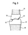
- Fig. 3 shows the tibia 30 and the femur 20 as well as the tibia implant 40 and the femur implant 50 which represent the virtual placement of the implants.
- the position of the femur implant 50 is matched and/or adjusted to the envelope points such that the implants 40 and 50 virtually touch each other at points 62 and 63 for each relative pose.
- the touch points 62, 63 in the reference system of the tibia represent a plurality of points in the reference system of the femur. These points are called envelope points.
- the femur implant is virtually placed.
- a representation of the first implant in the first reference system is placed.
- This placement is done such that the femur implant is adjusted or matched relative to the plurality of envelope points preferably, such that the femur implant contacts the envelope points as close as possible so that in case of movement, the envelope points represent the touch points between the femur and the tibia.
- the surgeon it is up to the surgeon, to deviate from this proposal for placement which is a result of the virtual planning according to the present invention.
- a relative rotation of the limb axis i.e. of the tibia axis and the femur axis
- This predetermined range may be described by degrees of relative rotation of the limb axis.
- the upper limit of the range may be between 0 and 10 degree, preferably between 1 and 5 degree, preferably between 2 and 4 degree, preferably about 3 degree.
- the situation in extension of the limbs may be used as a starting point. In extension, there is generally no relative rotation of the limbs.
- a relative rotation of one of the reference systems with respect to the limb axis fixed in the other reference system may be calculated.
- the relative rotation describes the rotational degree with respect to the starting situation, i.e. the situation of full extension.
- the relative pose data may be acquired by relative movement of the limbs.
- this pre-operative deformity may be corrected by external force to be within a predetermined, i.e. an acceptable range.
- this external force may be applied in order to assure that all relative pose data relate to a situation of corrected deformity.
- the situation as shown in Fig. 4 may be given, In Fig. 4 the femur axis 20 is shown in case of no deformity.
- the position of femur axis 20' is shown for deformation after appliance of force where the deformation is acceptable. For instance, the degree of deformation is 20.
- the position of the femoral axis 20" shows a situation where there is a deformation before appliance of force, i.e. no corrected deformation.
- the angle ⁇ between the location 20' and 20" may be detected as described in the parallel application.
- the angle ⁇ describes the difference between the uncorrected relative pose (forceless situation) and the corrected relative pose (force situation).
- This detected angle ⁇ may be used to calculate the relative pose data in case the relative movement is performed without applying a correction force in order to correct the deformity. If uncorrected relative pose data (representing the relative pose between the reference systems) are acquired by relative movement of the limbs without external force (i.e.
- this data may be used in order to calculated corrected relative pose data which describes the situation where the deformity is corrected, to be within an acceptable range. This may be done by using the angle ⁇ or distance determined in case of extension of the limbs and to correct the relative pose based on this angle ⁇ in order to virtually place the axis 20" to the position 20'.
- the femur implant is adjusted to the tibia implant, this is preferably done by virtually rotating the femur implant 50 around an axis 70 which is perpendicular to the femur axis 20 shown in Fig. 5 .
- this axis penetrates virtually the femur implant 50.
- This rotation movement is called a tilting movement of the femur implant.
- a virtual translational movement along the axis 20 is preferably performed by the virtual implant 50.
- the implant 50 is placed at a predefined position relative to the femur axis 20.
- a victual tilting movement and translational movement is performed until a preferred relative position between contact points 52 and 54 of the femur implant and the envelope points is achieved.
- a position is selected and preferred to be determined where the contact points 52 and 54 of the femur implant 50 contact the envelope points.
- the tilting movement is shown by the arrow B in Fig. 5 and the translational movement by the arrow A in Fig. 5 .
- the contact points 52 and 54 of the femur implant 50 are predetermined points which are selected to be most appropriate to contact the envelope points.
- the position of the femur implant is determined relative to the position of the tibia implant.
- cutting planes may be planned. The surgeon may later use the planned cutting planes in order to cut the tibia and the femur along the planes and to then attach the implants to the tibia and the femur.
- a so-called "joint line” is calculated based on the planned location of the femur implant and the tibia implant. This joint line describes an axis of rotation in case of a flexion movement of the limbs.
- the method of the present invention Joint allows the user or surgeon to move the joint line to a different position. Based on the displacement of the joint line and based on the previous location of the virtual femur implant and tibia, implant, the planning method of the present invention calculates the new and displaced position of the femur implant and the tibia implant.
- the implants are selected out of a plurality of virtual candidate implants based on the adjusting process of the femur implant to the tibia implant.
- a tibia implant is selected by a surgeon.
- the contact or surface points 62 and 63 are determined.
- a femur implant is selected out of the plurality of virtual candidate femur implants which selected femur implant allows for best adjustment of the femur implant to the envelope points.
- the selection procedure may be based on a calculation of deviation of the femur implant from the envelope points for the different candidate virtual femur implants. That femur implant is selected out of the candidate femur implants for which the minimal deviation has been calculated.
- An exemplary method for pre-operatively determining a degree of deformity of an anatomical structure joining to limbs may be used to determine a degree of deformity of an anatomical joint, e.g. a knee-joint joining femur and tibia, respectively or of an elbow joint.
- an anatomical joint e.g. a knee-joint joining femur and tibia, respectively or of an elbow joint.
- the above mentioned correction degree or correction vector may be determined as described in the following.
- a degree of deformity of an anatomical structure joining two limbs comprises the relative angular orientation or angular difference of axis corresponding to the two limbs.
- the degree of deformity is measured in angular degrees.
- An angular difference of a predetermined angle e. g. of up to 3° or 4° may be considered as a mild deformity.
- An angular difference greater than the predetermined angle but lower than another higher predetermined angle, e. g. between 3° and 5° or 4° and 6° may be considered as a moderate deformity.
- the deformity may comprise varus and valgus deformity.
- An exemplary method may comprise the step of providing data representing the pose of an axis of limb in a reference system in which the limb is fixed.
- a reference system in which a limb is fixed i.e. representing poses of the limb, may be provided by a marker array fixedly coupled to the limb, as described above.
- This marker array is also called reference array.
- an additional locating device or locating devices are brought into selected poses determining the axis and measured in the reference system in which the limb is fixed, as described above.
- An exemplary method may provide data representing poses of a first limb (e. g. femur) in a first reference system in which the first limb is fixed and of a second axis of the second limb (e. g. tibia) in a reference system in which the second limb is fixed, the first and second limb being joined by an anatomical structure, e.g. the knee joint.
- a first limb e. g. femur
- a second axis of the second limb e. g. tibia
- An exemplary method may further comprise the step of providing pose orientation data representing a relative pose between the first and second reference system with the first and second limb in extension, and with an external force being applied to eliminate or reduce the deformity of the anatomical structure.
- An external force may be applied to the first and second limb in extension in order to at least partially compensate the deformation of the anatomical structure.
- An exemplary method may further comprise the step of determining a relative angular orientation between the first axis of the first limb and the second axis of the second limb based on the force orientation data, said relative angular orientation being referred to as force relative angular orientation.
- Determining a relative angular orientation between the first and second axis from force orientation data may comprise determining a rotation between the first and second reference system with the first and second limb in extension, and with an external force being applied.
- a relative angular orientation may comprise components related to planes, e.g. a sagittal and/or coronal component. Splitting the relative angular orientation into components may simplify the assessment of degree of deformity of the anatomical structure.
- An exemplary method may further comprise the step of comparing force relative angular orientation with a relative angular orientation which is used as a reference.
- An exemplary method may further obtain the reference relative orientation by the step of providing forceless orientation data representing a relative pose between the first and second reference system with the first and second limb in extension and without an external force being applied.
- the pose of a limb in a reference system may be represented by the pose of an axis of the limb and/or by poses of landmarks of the limb.
- An axis of the limb is in particular a characteristical axis of the limb along the extension of the limb.
- An exemplary method may obtain the reference relative angular orientation by the further step of determining the reference relative angular orientation, i. e. a forceless relative angular orientation, between the poses of the limbs e.g. between the first axis of the first limb and the second axis of the second limb based on forceless orientation data.
- a method according to the invention may be executed by a computer program loaded by executed on a general purpose computer, a dedicated computer or a computer on a chip,
- An exemplary method may obtain a difference vector between the force relative angular orientation and the forceless relative angular orientation in order to obtain the correction degree or correction vector suitable to virtually correct a pre-operative deformity of the anatomical structure joining the first and second limb.
Landscapes
- Health & Medical Sciences (AREA)
- Surgery (AREA)
- Engineering & Computer Science (AREA)
- Life Sciences & Earth Sciences (AREA)
- Medical Informatics (AREA)
- Robotics (AREA)
- Biomedical Technology (AREA)
- Heart & Thoracic Surgery (AREA)
- Nuclear Medicine, Radiotherapy & Molecular Imaging (AREA)
- Molecular Biology (AREA)
- Animal Behavior & Ethology (AREA)
- General Health & Medical Sciences (AREA)
- Public Health (AREA)
- Veterinary Medicine (AREA)
- Prostheses (AREA)
- Measurement Of The Respiration, Hearing Ability, Form, And Blood Characteristics Of Living Organisms (AREA)
Claims (8)
- Verfahren zum Planen von Implantatplatzierung, wobei das Implantat ein erstes Implantat (50) in einer ersten Gliedmaße (20) und ein zweites Implantat (40) in einer zweiten Gliedmaße (30) enthält, wobei das erste und das zweite Implantat eine künstliche Gelenkstruktur bilden, die die erste und zweite Gliedmaße verbindet, wobei das Verfahren folgende Schritte enthält:a) Bereitstellen eines ersten Gliedmaßendatensatzes, der ein erstes Bezugssystem darstellt, in dem die erste Gliedmaße fixiert ist;b) Bereitstellen eines zweiten Gliedmaßendatensatzes, der ein zweites Bezugssystem darstellt, in dem die zweite Gliedmaße fixiert ist;c) Bereitstellen einer Repräsentation des Implantats (40) für den Kopf der zweiten Gliedmaße in einer bekannten Position in dem zweiten Bezugssystem;d) Bereitstellen von Relativposedaten, die eine Mehrzahl verschiedener relativer Positionen und/oder Orientierungen, nachfolgend als relative Posen in Bezug genommen, des ersten und des zweiten Bezugssystems darstellen;e) Bestimmen eines Datensatzes, der eine Mehrzahl von Einhüllendenpunkten darstellt, wobei die Einhüllendenpunkte erzeugt werden, indem die Orte eines Punkts (62, 63) der zweiten Implantatrepräsentation in dem ersten Bezugssystem für die Mehrzahl der relativen Posen berechnet werden; undf) Platzieren einer Repräsentation des ersten Implantats (50) in dem ersten Bezugssystem, indem die Pose der Repräsentation des ersten Implantats auf die Mehrzahl der Einhüllendenpunkte eingestellt und/oder an die Pose der Repräsentation des ersten Implantats mit der Mehrzahl der Einhüllendenpunkte in Übereinstimmung gebracht werden,
dadurch gekennzeichnet, dass
die Mehrzahl der Einhüllendenpunkte berechnet werden, indem der Ort eines zweiten Implantatpunkts in dem ersten Bezugssystem für die Mehrzahl der relativen Posen im Falle einer unkorrigierten Deformierung der anatomischen Gliedmaße mittels eines Korrekturvektors, der die Korrektur einer relativen Pose des ersten und zweiten Bezugssystems im Falle einer korrigierten Deformierung beschreibt, korrigiert wird. - Verfahren gemäß Anspruch 1, bei dem eine Repräsentation aus einer Mehrzahl von Repräsentation des ersten Implantats (50) in dem ersten Bezugssystem platziert wird und in Bezug auf die Mehrzahl der Einhüllendenpunkte eingestellt und/oder in Übereinstimmung gebracht wird und aus der Mehrzahl von Repräsentationen des ersten Implantats (50) diejenige Repräsentation ausgewählt wird, für die die beste Einstellung und/oder Übereinstimmung erzielbar ist.
- Verfahren gemäß einem der vorhergehenden Ansprüche, bei dem das Bereitstellen der Relativposedaten, die eine Mehrzahl verschiedener Posen des ersten und zweiten Bezugssystems darstellen, enthält, dass Referenzanordnungen, die an der ersten Gliedmaße und der zweiten Gliedmaße angebracht sind, während einer Bewegung der zweiten Gliedmaße relativ zur ersten Gliedmaße detektiert werden, wobei die Bewegung eine Flexion und/oder Extension der zweiten Gliedmaße relativ zur ersten Gliedmaße enthält.
- Verfahren gemäß irgendeinem der vorhergehenden Ansprüche, bei dem die Implantatplatzierung für eine totale Kniearthroplastik geeignet ist, wobei die die erste und zweite Gliedmaße verbindende künstliche Struktur ein künstliches Kniegelenk enthält und die erste bzw. zweite Gliedmaße einen Femur bzw. eine Tibia enthalten.
- Verfahren gemäß irgendeinem der vorhergehenden Ansprüche, bei dem der Platzierungsschritt ferner enthält:Versetzen der Repräsentation des ersten Implantats entlang einer Achse der ersten Gliedmaße und/oder Kippen der Repräsentation des ersten Implantats relativ zur Achse der ersten Gliedmaße.
- Verfahren gemäß irgendeinem der vorhergehenden Ansprüche, wobei das Verfahren ferner enthält:Registrieren einer Achse der ersten Gliedmaße in dem ersten Bezugssystem und einer Achse der zweiten Gliedmaße in dem zweiten Bezugssystem.
- Programm, das, wenn es auf einem Computer abläuft oder in einen Computer geladen ist, das Verfahren gemäß irgendeinem der vorhergehenden Ansprüche ausführt.
- System, enthaltend:einen Computer (200), auf den das Programm aus dem vorhergehenden Anspruch läuft oder in den es geladen ist, undeinen Detektor (100), der funktionsfähig mit dem Computer gekoppelt ist, zum Detektieren von Lokalisierungsvorrichtungen oder Referenzmarkern, die Posen darstellen.
Priority Applications (2)
| Application Number | Priority Date | Filing Date | Title |
|---|---|---|---|
| EP08154210.2A EP2103271B1 (de) | 2008-03-19 | 2008-04-08 | Gelenkimplantatanordnung |
| US12/407,031 US8172775B2 (en) | 2008-03-19 | 2009-03-19 | Joint implant placement |
Applications Claiming Priority (2)
| Application Number | Priority Date | Filing Date | Title |
|---|---|---|---|
| EP08153031A EP2103259B1 (de) | 2008-03-19 | 2008-03-19 | Verfahren und System zur Bestimmung eines Deformitätsgrades einer anatomischen Verbindungsstelle |
| EP08154210.2A EP2103271B1 (de) | 2008-03-19 | 2008-04-08 | Gelenkimplantatanordnung |
Publications (2)
| Publication Number | Publication Date |
|---|---|
| EP2103271A1 EP2103271A1 (de) | 2009-09-23 |
| EP2103271B1 true EP2103271B1 (de) | 2014-03-26 |
Family
ID=39682621
Family Applications (2)
| Application Number | Title | Priority Date | Filing Date |
|---|---|---|---|
| EP08153031A Expired - Fee Related EP2103259B1 (de) | 2008-03-19 | 2008-03-19 | Verfahren und System zur Bestimmung eines Deformitätsgrades einer anatomischen Verbindungsstelle |
| EP08154210.2A Not-in-force EP2103271B1 (de) | 2008-03-19 | 2008-04-08 | Gelenkimplantatanordnung |
Family Applications Before (1)
| Application Number | Title | Priority Date | Filing Date |
|---|---|---|---|
| EP08153031A Expired - Fee Related EP2103259B1 (de) | 2008-03-19 | 2008-03-19 | Verfahren und System zur Bestimmung eines Deformitätsgrades einer anatomischen Verbindungsstelle |
Country Status (2)
| Country | Link |
|---|---|
| US (2) | US20090254002A1 (de) |
| EP (2) | EP2103259B1 (de) |
Families Citing this family (18)
| Publication number | Priority date | Publication date | Assignee | Title |
|---|---|---|---|---|
| CA2683717C (en) | 2007-04-19 | 2016-10-11 | Mako Surgical Corp. | Implant planning using captured joint motion information |
| US9364291B2 (en) | 2008-12-11 | 2016-06-14 | Mako Surgical Corp. | Implant planning using areas representing cartilage |
| JP2011157155A (ja) | 2010-01-29 | 2011-08-18 | Brother Industries Ltd | 画像記録装置 |
| US8496704B2 (en) | 2010-04-13 | 2013-07-30 | Smith & Nephew, Inc. | Systems and methods for tensioning ligaments and other soft tissues |
| US20120035507A1 (en) * | 2010-07-22 | 2012-02-09 | Ivan George | Device and method for measuring anatomic geometries |
| US8696675B2 (en) | 2010-08-31 | 2014-04-15 | Orthosoft Inc. | Proximity-triggered computer-assisted surgery system and method |
| WO2013021357A1 (en) * | 2011-08-08 | 2013-02-14 | Ecole Polytechnique Federale De Lausanne (Epfl) | In-vivo condition monitoring of metallic implants by electrochemical techniques |
| WO2016049151A1 (en) * | 2014-09-24 | 2016-03-31 | Depuy (Ireland) | Surgical planning and method |
| DE102018201612A1 (de) * | 2018-02-02 | 2019-08-08 | Carl Zeiss Industrielle Messtechnik Gmbh | Verfahren und Vorrichtung zur Erzeugung eines Steuersignals, Markeranordnung und steuerbares System |
| WO2019245862A1 (en) | 2018-06-19 | 2019-12-26 | Tornier, Inc. | Visualization of intraoperatively modified surgical plans |
| US11278416B2 (en) | 2019-11-14 | 2022-03-22 | Howmedica Osteonics Corp. | Concentric keel TKA |
| AU2020404991B2 (en) | 2019-12-18 | 2023-10-19 | Howmedica Osteonics Corp. | Surgical guidance for surgical tools |
| US11816831B2 (en) | 2020-04-29 | 2023-11-14 | Medtronic Navigation, Inc. | System and method for navigating and illustrating a procedure |
| US11890060B2 (en) * | 2020-04-29 | 2024-02-06 | Medtronic Navigation, Inc. | System and method for navigating and illustrating a procedure |
| US12533805B2 (en) | 2020-10-30 | 2026-01-27 | Mako Surgical Corp. | Robotic surgical system with cut selection logic |
| US12527632B2 (en) | 2020-12-15 | 2026-01-20 | Mako Surgical Corp. | Systems and methods for initial assessment warnings |
| USD1044829S1 (en) | 2021-07-29 | 2024-10-01 | Mako Surgical Corp. | Display screen or portion thereof with graphical user interface |
| US12458442B2 (en) | 2023-06-30 | 2025-11-04 | Depuy Ireland Unlimited Company | Apparatus, system, and method for bone loss compensation of a patient's knee joint during an orthopaedic surgical procedure |
Family Cites Families (9)
| Publication number | Priority date | Publication date | Assignee | Title |
|---|---|---|---|---|
| US5828770A (en) | 1996-02-20 | 1998-10-27 | Northern Digital Inc. | System for determining the spatial position and angular orientation of an object |
| EP1079756B1 (de) * | 1998-05-28 | 2004-08-04 | Orthosoft, Inc. | Interaktives und rechnerunterstüztes chirurgisches system |
| US6701174B1 (en) | 2000-04-07 | 2004-03-02 | Carnegie Mellon University | Computer-aided bone distraction |
| FR2816200A1 (fr) | 2000-11-06 | 2002-05-10 | Praxim | Determination de la position d'une prothese du genou |
| EP1501406A4 (de) * | 2002-04-16 | 2006-08-30 | Philip C Noble | Computergestützte schulungsverfahren für chirurgische eingriffe |
| DE10313747A1 (de) * | 2003-03-27 | 2004-10-28 | Aesculap Ag & Co. Kg | Verfahren und Vorrichtung zur Bestimmung eines Gelenkpunktes von zwei Knochen |
| US20070066917A1 (en) | 2005-09-20 | 2007-03-22 | Hodorek Robert A | Method for simulating prosthetic implant selection and placement |
| US20070179626A1 (en) | 2005-11-30 | 2007-08-02 | De La Barrera Jose L M | Functional joint arthroplasty method |
| US8337508B2 (en) * | 2006-03-20 | 2012-12-25 | Perception Raisonnement Action En Medecine | Distractor system |
-
2008
- 2008-03-19 EP EP08153031A patent/EP2103259B1/de not_active Expired - Fee Related
- 2008-04-08 EP EP08154210.2A patent/EP2103271B1/de not_active Not-in-force
-
2009
- 2009-03-19 US US12/407,027 patent/US20090254002A1/en not_active Abandoned
- 2009-03-19 US US12/407,031 patent/US8172775B2/en not_active Expired - Fee Related
Also Published As
| Publication number | Publication date |
|---|---|
| US20090240169A1 (en) | 2009-09-24 |
| EP2103259A1 (de) | 2009-09-23 |
| US20090254002A1 (en) | 2009-10-08 |
| US8172775B2 (en) | 2012-05-08 |
| EP2103259B1 (de) | 2012-01-25 |
| EP2103271A1 (de) | 2009-09-23 |
Similar Documents
| Publication | Publication Date | Title |
|---|---|---|
| EP2103271B1 (de) | Gelenkimplantatanordnung | |
| CA2607036C (en) | Leg alignment for surgical parameter measurement in hip replacement surgery | |
| AU2008323521B2 (en) | Leg alignment and length measurement in hip replacement surgery | |
| EP3322337B1 (de) | Computer-implementiertes verfahren zur berechnung der beinlängen der unteren extremitäten | |
| EP2247254B1 (de) | Computer assistiertes chirurgiesystem | |
| US8790351B2 (en) | Hip replacement in computer-assisted surgery | |
| US9949665B2 (en) | Method, system and device for positioning an implant | |
| KR101837301B1 (ko) | 수술 항법 시스템 | |
| US10463506B2 (en) | Acetabular implant alignment devices and methods | |
| AU2002246466A1 (en) | Computer assisted insertion of an artifical hip joint | |
| JP2008526427A (ja) | 膝関節形成術におけるコンピュータ支援による靭帯バランシング | |
| CN115500944B (zh) | 膝关节骨科手术导航系统 | |
| Harris et al. | Intra-operative application of a robotic knee surgery system | |
| CN116831731A (zh) | 用于髋关节置换手术的机械臂辅助导航系统及手术系统 | |
| US9042621B2 (en) | Intra-operative surgical plan changing | |
| CN115844546A (zh) | 骨骼的切削方法、装置、存储介质和处理器 | |
| WO2024246875A1 (en) | Orientation aid for orienting a bone section | |
| Perlick et al. | Cup and stem navigation with the VectorVision system |
Legal Events
| Date | Code | Title | Description |
|---|---|---|---|
| PUAI | Public reference made under article 153(3) epc to a published international application that has entered the european phase |
Free format text: ORIGINAL CODE: 0009012 |
|
| 17P | Request for examination filed |
Effective date: 20080408 |
|
| AK | Designated contracting states |
Kind code of ref document: A1 Designated state(s): AT BE BG CH CY CZ DE DK EE ES FI FR GB GR HR HU IE IS IT LI LT LU LV MC MT NL NO PL PT RO SE SI SK TR |
|
| AX | Request for extension of the european patent |
Extension state: AL BA MK RS |
|
| 17Q | First examination report despatched |
Effective date: 20091111 |
|
| AKX | Designation fees paid |
Designated state(s): DE FR GB |
|
| RAP1 | Party data changed (applicant data changed or rights of an application transferred) |
Owner name: BRAINLAB AG |
|
| GRAP | Despatch of communication of intention to grant a patent |
Free format text: ORIGINAL CODE: EPIDOSNIGR1 |
|
| INTG | Intention to grant announced |
Effective date: 20131212 |
|
| GRAS | Grant fee paid |
Free format text: ORIGINAL CODE: EPIDOSNIGR3 |
|
| GRAA | (expected) grant |
Free format text: ORIGINAL CODE: 0009210 |
|
| AK | Designated contracting states |
Kind code of ref document: B1 Designated state(s): DE FR GB |
|
| REG | Reference to a national code |
Ref country code: GB Ref legal event code: FG4D |
|
| REG | Reference to a national code |
Ref country code: DE Ref legal event code: R096 Ref document number: 602008031083 Country of ref document: DE Effective date: 20140508 |
|
| REG | Reference to a national code |
Ref country code: DE Ref legal event code: R097 Ref document number: 602008031083 Country of ref document: DE |
|
| PLBE | No opposition filed within time limit |
Free format text: ORIGINAL CODE: 0009261 |
|
| STAA | Information on the status of an ep patent application or granted ep patent |
Free format text: STATUS: NO OPPOSITION FILED WITHIN TIME LIMIT |
|
| 26N | No opposition filed |
Effective date: 20150106 |
|
| REG | Reference to a national code |
Ref country code: DE Ref legal event code: R097 Ref document number: 602008031083 Country of ref document: DE Effective date: 20150106 |
|
| REG | Reference to a national code |
Ref country code: FR Ref legal event code: PLFP Year of fee payment: 8 |
|
| PGFP | Annual fee paid to national office [announced via postgrant information from national office to epo] |
Ref country code: DE Payment date: 20150421 Year of fee payment: 8 Ref country code: GB Payment date: 20150420 Year of fee payment: 8 |
|
| PGFP | Annual fee paid to national office [announced via postgrant information from national office to epo] |
Ref country code: FR Payment date: 20150421 Year of fee payment: 8 |
|
| REG | Reference to a national code |
Ref country code: DE Ref legal event code: R119 Ref document number: 602008031083 Country of ref document: DE |
|
| GBPC | Gb: european patent ceased through non-payment of renewal fee |
Effective date: 20160408 |
|
| REG | Reference to a national code |
Ref country code: FR Ref legal event code: ST Effective date: 20161230 |
|
| PG25 | Lapsed in a contracting state [announced via postgrant information from national office to epo] |
Ref country code: FR Free format text: LAPSE BECAUSE OF NON-PAYMENT OF DUE FEES Effective date: 20160502 Ref country code: DE Free format text: LAPSE BECAUSE OF NON-PAYMENT OF DUE FEES Effective date: 20161101 Ref country code: GB Free format text: LAPSE BECAUSE OF NON-PAYMENT OF DUE FEES Effective date: 20160408 |