EP2103506A2 - Flurförderzeug - Google Patents
Flurförderzeug Download PDFInfo
- Publication number
- EP2103506A2 EP2103506A2 EP09002041A EP09002041A EP2103506A2 EP 2103506 A2 EP2103506 A2 EP 2103506A2 EP 09002041 A EP09002041 A EP 09002041A EP 09002041 A EP09002041 A EP 09002041A EP 2103506 A2 EP2103506 A2 EP 2103506A2
- Authority
- EP
- European Patent Office
- Prior art keywords
- spring
- driver
- damper elements
- workplace
- axis
- Prior art date
- Legal status (The legal status is an assumption and is not a legal conclusion. Google has not performed a legal analysis and makes no representation as to the accuracy of the status listed.)
- Granted
Links
- 238000013016 damping Methods 0.000 description 16
- 238000010276 construction Methods 0.000 description 7
- 239000000725 suspension Substances 0.000 description 7
- 238000005516 engineering process Methods 0.000 description 2
- 230000005484 gravity Effects 0.000 description 2
- 238000005096 rolling process Methods 0.000 description 2
- 230000035939 shock Effects 0.000 description 2
- 230000006978 adaptation Effects 0.000 description 1
- 230000002238 attenuated effect Effects 0.000 description 1
- 230000003068 static effect Effects 0.000 description 1
Images

Classifications
-
- B—PERFORMING OPERATIONS; TRANSPORTING
- B62—LAND VEHICLES FOR TRAVELLING OTHERWISE THAN ON RAILS
- B62D—MOTOR VEHICLES; TRAILERS
- B62D33/00—Superstructures for load-carrying vehicles
- B62D33/06—Drivers' cabs
- B62D33/0604—Cabs insulated against vibrations or noise, e.g. with elastic suspension
-
- B—PERFORMING OPERATIONS; TRANSPORTING
- B62—LAND VEHICLES FOR TRAVELLING OTHERWISE THAN ON RAILS
- B62D—MOTOR VEHICLES; TRAILERS
- B62D51/00—Motor vehicles characterised by the driver not being seated
- B62D51/02—Motor vehicles characterised by the driver not being seated the driver standing in the vehicle
-
- B—PERFORMING OPERATIONS; TRANSPORTING
- B60—VEHICLES IN GENERAL
- B60N—SEATS SPECIALLY ADAPTED FOR VEHICLES; VEHICLE PASSENGER ACCOMMODATION NOT OTHERWISE PROVIDED FOR
- B60N2/00—Seats specially adapted for vehicles; Arrangement or mounting of seats in vehicles
- B60N2/24—Seats specially adapted for vehicles; Arrangement or mounting of seats in vehicles for particular purposes or particular vehicles
- B60N2002/247—Seats specially adapted for vehicles; Arrangement or mounting of seats in vehicles for particular purposes or particular vehicles to support passengers in a half-standing position
Definitions
- the invention relates to an industrial truck, in particular storage technology device, with a frame and a driver's workplace, which is spring-mounted and / or damped on the frame by means of at least one spring and / or damper element.
- the damping elements in this case allow movement of the driver's cab in the vertical direction and in the horizontal direction.
- a tilting of the driver's workplace about a horizontal transverse axis, a yawing of the driver's workplace about a vertical vertical axis and a rolling of the driver's workplace about a horizontal longitudinal axis can not be effectively damped.
- an adaptation to the weight of an operator is not provided.
- the present invention has for its object to provide an industrial truck of the type mentioned, which is improved in terms of comfort for the operator.
- the spring and / or damper element is arranged inclined in the vertical direction.
- the spring and / or damper elements are subjected to pressure and thrust.
- the angle of the spring and / or damper element relative to the vertical plane thus the stiffness of the spring and / or Damper element in the vertical direction changed in a simple manner and adapted, for example, to different weights of the operator.
- the inventive arrangement of the spring and / or damper elements is thus in a simple manner and with low construction costs, an improvement in comfort for the operator located on the driver's workplace achievable.
- a three-point bearing with three spring and / or damper elements is provided for supporting the driver's workplace on the frame.
- a static certain spring-mounted storage of the driver's workplace can be achieved with low construction costs.
- a four-point bearing with four spring and / or damper elements is provided for supporting the driver's workplace on the frame.
- a point bearing allows not only damping or suspension of the driver's workplace in the vertical direction, in the vehicle longitudinal direction and in the vehicle transverse direction further damping of tilting the driver's workplace about a horizontal transverse axis, damping the yawing of the driver's workplace about a vertical vertical axis and a damping of the rolling of the driver's workplace a horizontal longitudinal axis.
- At least two spring and / or damper element are provided, which are spaced in the vehicle longitudinal direction, wherein the spring and / or damper element to each other in an vertical plane at an angle in the range of 10 ° to 90 °.
- the spring and / or damper elements are arranged inclined in the horizontal direction and at least two spring and / or damper element are provided, which are spaced in the vehicle transverse direction, wherein the spring and / or damper elements to each other in an horizontal plane an angle in the range of 10 ° to 90 °.
- the driver's workplace has a front wall and a rear wall spaced in the vehicle longitudinal direction, wherein between the front wall and the frame two spaced in the vehicle transverse direction spring and / or damper elements and between the rear wall and the frame two spaced in the vehicle transverse direction spring and / or damper elements are arranged.
- the spring and / or damper elements are arranged in the vertical upper region of the driver's workplace.
- the spring and / or damper elements are thus arranged in the region of the overall center of gravity of the driver's workplace and the operator thereon, resulting in small movement deflections of the driver's workplace, in particular due to inertia, which increase comfort.
- the spring and / or damper elements are expediently attached to the frame, wherein the driver's workplace is provided with receptacles for the spring and / or damper elements.
- the driver's workplace is provided with receptacles for the spring and / or damper elements.
- the angle of the spring and / or damper elements in the vertical plane and / or the angle of the spring and / or damper elements in the horizontal plane is adjustable, the spring and damping behavior of the driver's workplace can be easily adapted and to different weights of Adjusted operator.
- the spring and / or damper elements are designed as rubber spring elements.
- pressure and shear loaded spring and / or damper elements can be provided with low construction costs, resulting in a low construction cost for the inventive storage of the driver's workplace.
- the spring and / or damper elements have a higher rigidity in a compressive load than in a shear load, the adjustability of the angle of the spring and / or damper elements in the vertical plane and in the horizontal plane, the damping and suspension behavior of the driver's workplace easy way to be set.
- the driver's workplace is designed as a driver's platform with an operating device and / or a leaning.
- the control device such as a handlebar assembly
- the hands and operating on the trained example as a back cushion or standing seat leaning support operator is thus completely decoupled via the driver's cab vibration technology.
- the operator is decoupled in a simple manner and with low construction costs of acting road shocks and vibrations, whereby the loads acting on the operator can be effectively reduced and a truck with a high level of comfort for the operator can be achieved.
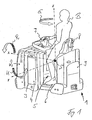
- FIG. 1 shows an inventive designed as a warehouse truck industrial truck 1 in a side view.
- the truck 1 has seen in the direction of travel on a front-side drive part 2, in which, for example, a not-shown steerable drive wheel, an electric traction drive motor, a service brake and a power electronics unit are.
- a battery compartment 3 Adjacent to the drive part 2, a battery compartment 3 is formed with a battery block 4 arranged therein. Adjacent to the battery compartment 3 is a driver's workplace 5, which has a driver's platform 6 for a standing operator B and a handlebar-like operating arrangement 7, by means of which the steering and the travel drive of the tractor 1 can be controlled.
- the driver's workplace 5 furthermore comprises a leaning aid 8 designed, for example, as a standing seat.
- the leaning aid 8 can here be arranged to be height-adjustable on the driver's workplace 5.
- the operator B can lean on the leaning 8 and support part of their weight on the leaning 8. This prevents a rapid fatigue of the operator B and also ensures a secure position of the operator B on the driver's platform 5.
- Adjacent to the driver's workplace 5, the truck 1 is provided with a vertical frame wall 9.
- the driver's workplace 5 has - as from FIG. 2 it can be seen - on a substantially vertical front wall 10 on which the operating assembly 7 is fixed, and a substantially vertical rear wall 11 on which the leaning 8 arranged. Between the front wall 10 and the rear wall 11, the operator platform 6 is arranged.
- the truck 1 has a supporting frame 12 which, of the vertical frame wall 9, one in the region of Battery compartment 3 arranged vertical frame wall 13 and at least one of the frame wall 13 with the frame wall 9 connecting longitudinal member 14 is formed.
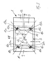
- the driver's workplace is 5 - as in the FIG. 3 is shown - sprung and damped on the frame 12 by means of one of four spring and / or damper elements 15a, 15b, 16a, 16b formed four-point storage.
- the spring and / or damper elements 15a, 15b are hereby spaced apart in the vehicle transverse direction (axis Y) and arranged between the front wall 10 of the driver's workplace 5 and the frame wall 13 of the frame 12.
- the spring and / or damper elements 16a, 16b are spaced from the spring and / or damper elements 15a, 15b in the vehicle longitudinal direction (axis X) and likewise spaced apart in the vehicle transverse direction (axis Y), wherein the spring and / or damper elements 16a, 16 b are arranged between the rear wall 11 of the driver's workplace 5 and the frame wall 9 of the frame 12.
- the spring and / or damper elements 15a, 15b and 16a, 16b are in each case inclined in the vertical direction.
- the spring and / or damper elements 15a, 15b are in this case inclined relative to the vertical (axis Z) in a range of 5 ° to 45 ° to the rear in the direction of the driver's workplace 5.
- the spring and / or damper elements 16a, 16b are inclined relative to the vertical (axis Z) in a range of 5 ° to 45 ° forward in the direction of the driver's workplace.
- the spaced apart in the vehicle longitudinal direction spring and / or damper elements 15a, 16a and 15b, 16b thus close - as from FIG. 2 can be seen - in a vertical plane, which is spanned by the axes X and Z, to each other an angle W1 in the range of 10 ° to 90 °.
- the spring and / or damper element 15a, 15b further inclined in the horizontal direction, wherein the spring and / or damper elements 15a and 15b respectively facing inwardly relative to a vehicle longitudinal axis (axis X) by an angle in the range of 5 ° to 45 ° are arranged inclined.
- the spring and / or damper elements 16a, 16b are inclined in the horizontal direction and in each case inclined inwards relative to a vehicle longitudinal axis (axis X) at an angle in the range of 5 ° to 45 °.
- the spring and / or damper elements 15a, 15b and 16a, 16b are here - as shown in FIG. 2 can be seen in the vertical upper area of the driver's workplace 5 in the range of the height of the total center of gravity S of the driver's workplace 5 and the operator B arranged.
- the vehicle longitudinal axis (axis X) are in the vehicle transverse direction (axis Y) spaced spring and / or damper elements 15a, 15b and 16a, 16b are also inclined by 45 °, resulting in each case an angle W2 of 90 °.
- the spring and / or damper elements 15a, 15b and 16a, 16b are in this case arranged on corresponding fastening brackets 17a, 17b or 18a, 18b, the fastening brackets 17a, 17b on the frame wall 13 and the fastening brackets 18a, 18b on the frame wall 9 are arranged.
- On the front wall 10 of the driver's workplace 5 are here corresponding receptacles 19a, 19b for the spring and / or damper elements 15a, 15b and on the rear wall 11 of the driver's workplace 5 corresponding receptacles 20a, 20b for the spring and / or damper elements 16a, 16b formed ,
- the spring and / or damper elements 15a, 15b and 16a, 16b are each formed as rubber spring elements, which have a higher rigidity at a pressure load than at a thrust load.
- a suspension and damping of Driver workplace 5 in the vehicle longitudinal direction (axis X), in the vehicle transverse direction (axis Y) and in the vertical direction (axis Z) can be achieved.
- a role R of the driver's workplace 5 around a horizontal longitudinal axis (X axis) effectively attenuated.
- the suspension and damping of the driver's workplace 5 are adapted to different weights of the operator B, wherein the stiffness in the vertical direction (axis Z) regardless of the stiffness in the horizontal plane (axes X and Y) can be changed.
- an automatic adjustment of the position and the location of the driver's workplace 5 in the frame 12 of the truck 1 can be achieved by the storage invention. Furthermore, there are small movement deflections of the driver's workplace 5 due to inertia.
- a truck 1 is achieved with a high level of comfort for the operator B, in which the operator B is exposed during operation low impact loads and vibrations.
- the truck 1 according to the invention can in this case - as in the FIG. 1 is shown - be designed as a tractor, wherein arranged in the region of the frame wall 9 a hitch.
- the truck according to the invention it is also possible to form the truck according to the invention as Niederhubkommissionierer or as a picker, wherein in the region of the frame wall, a load-receiving means is arranged.
Landscapes
- Engineering & Computer Science (AREA)
- Chemical & Material Sciences (AREA)
- Combustion & Propulsion (AREA)
- Transportation (AREA)
- Mechanical Engineering (AREA)
- Body Structure For Vehicles (AREA)
- Springs (AREA)
Abstract
Description
- Die Erfindung betrifft ein Flurförderzeug, insbesondere Lagertechnikgerät, mit einem Rahmen und einem Fahrerarbeitsplatz, der am Rahmen mittels mindestens eines Feder- und/oder Dämpferelements gefedert und/oder gedämpft gelagert ist.
- Aus der
WO 96/24519 - Die Dämpfungselemente erlauben hierbei eine Bewegung des Fahrerstandes in vertikaler Richtung und in horizontaler Richtung. Bei der aus der
WO 96/24519 - Der vorliegenden Erfindung liegt die Aufgabe zugrunde, ein Flurförderzeug der eingangs genannten Gattung zur Verfügung zu stellen, das hinsichtlich des Komforts für die Bedienperson verbessert ist.
- Diese Aufgabe wird erfindungsgemäß dadurch gelöst, dass das Feder- und/oder Dämpferelement in vertikaler Richtung geneigt angeordnet ist. Durch die gegenüber einer vertikalen Ebene geneigte Anordnung der Feder- und/oder Dämpferelemente werden die Feder- und/oder Dämpferelemente auf Druck und auf Schub beansprucht. Durch eine Veränderung des Winkels des Feder- und/oder Dämpferelements gegenüber der vertikalen Ebene kann somit die Steifigkeit des Feder- und/oder Dämpferelements in vertikaler Richtung auf einfache Weise verändert und beispielsweise an unterschiedliche Gewichte der Bedienperson angepasst werden. Durch die erfindungsgemäße Anordnung der Feder- und/oder Dämpferelemente ist somit auf einfache Weise und mit geringem Bauaufwand eine Verbesserung des Komforts für die auf dem Fahrerarbeitsplatz befindliche Bedienperson erzielbar.
- Gemäß einer Ausführungsform der Erfindung ist zur Lagerung des Fahrerarbeitsplatzes am Rahmen eine Dreipunktlagerung mit drei Feder- und/oder Dämpferelementen vorgesehen. Hierdurch ist mit geringem Bauaufwand eine statische bestimmte gefederte Lagerung des Fahrerarbeitsplatzes erzielbar.
- Besondere Vorteile ergeben sich, wenn gemäß einer Ausführungsform der Erfindung zur Lagerung des Fahrerarbeitsplatzes am Rahmen eine Vierpunktlagerung mit vier Feder- und/oder Dämpferelementen vorgesehen ist. Eine Verpunktlagerung ermöglicht neben einer Dämpfung bzw. Federung des Fahrerarbeitsplatzes in vertikaler Richtung, in Fahrzeuglängsrichtung sowie in Fahrzeugquerrichtung weiterhin eine Dämpfung des Kippens des Fahrerarbeitsplatzes um eine horizontale Querachse, eine Dämpfung des Gierens des Fahrerarbeitsplatzes um eine vertikale Hochachse und eine Dämpfung des Rollens des Fahrerarbeitsplatzes um eine horizontale Längsachse. Hierdurch ist ein hoher Komfort für die auf dem Fahrerarbeitsplatz befindliche Bedienperson und eine Verringerung der auf die Bedienperson einwirkenden Stoß- und Schwingungsbelastungen auf einfache Weise erzielbar.
- Gemäß einer Ausgestaltungsform der Erfindung sind hierbei mindestens zwei Feder- und/oder Dämpferelement vorgesehen, die in Fahrzeuglängsrichtung beabstandet sind, wobei die Feder- und/oder Dämpferelement zueinander in einer vertikalen Ebene einen Winkel im Bereich von 10° bis 90° einschließen. Durch eine Einstellung des Winkels der beiden in Fahrzeuglängsrichtung beabstandeten Feder- und/oder Dämpferelement in der vertikalen Ebene zueinander kann die Steifigkeit der Feder- und/oder Dämpferelemente in vertikaler Richtung verändert werden, wodurch auf einfache Weise eine Anpassung der Dämpfungs- und Federungseigenschaften an unterschiedliche Gewichte der Bedienperson und eine Einstellung der Dämpfung des Fahrerarbeitsplatzes hinsichtlich des Kippens um die horizontale Querachse erzielbar ist.
- Besondere Vorteile sind erzielbar, wenn gemäß einer Weiterbildung der Erfindung die Feder- und/oder Dämpferelemente in horizontaler Richtung geneigt angeordnet sind und mindestens zwei Feder- und/oder Dämpferelement vorgesehen sind, die in Fahrzeugquerrichtung beabstandet sind, wobei die Feder- und/oder Dämpferelemente zueinander in einer horizontalen Ebene einen Winkel im Bereich von 10° bis 90° einschließen. Durch die Einstellung des Winkels der in Fahrzeugquerrichtung beabstandeten Feder- und/oder Dämpferelemente zueinander in der horizontalen Ebene kann die Federung und Dämpfung des Fahrerarbeitsplatzes in Längsrichtung und Querrichtung sowie das Gieren um die vertikale Hochachse sowie das Rollen um die horizontale Längsachse eingestellt und angepasst werden.
- Hinsichtlich eines geringen Bauaufwandes ergeben sich Vorteile, wenn gemäß einer Ausgestaltungsform der Erfindung der Fahrerarbeitsplatz eine Vorderwand und eine in Fahrzeuglängsrichtung beabstandete Rückwand aufweist, wobei zwischen der Vorderwand und dem Rahmen zwei in Fahrzeugquerrichtung beabstandete Feder- und/oder Dämpferelemente und zwischen der Rückwand und dem Rahmen zwei in Fahrzeugquerrichtung beabstandete Feder- und/oder Dämpferelemente angeordnet sind. Durch eine derartige Anordnung der Feder- und/oder Dämpferelemente zwischen dem Rahmen und einer im Wesentlichen vertikalen Vorderwand sowie einer im Wesentlichen vertikalen Rückwand des Fahrerarbeitsplatzes kann eine Vierpunktlagerung des Fahrerarbeitsplatzes mit geringem Bauaufwand und geringem Bauraumbedarf erzielt werden.
- Gemäß einer bevorzugten Weiterbildung der Erfindung sind die Feder- und/oder Dämpferelemente im vertikal oberen Bereich des Fahrerarbeitsplatzes angeordnet. Die Feder- und/oder Dämpferelemente sind somit im Bereich des Gesamtschwerpunktes des Fahrerarbeitsplatzes und der darauf befindlichen Bedienperson angeordnet, wodurch sich kleine Bewegungsauslenkungen des Fahrerarbeitsplatzes insbesondere aufgrund der Massenträgheit ergeben, die sich Komfort erhöhend auswirken.
- Die Feder- und/oder Dämpferelemente sind zweckmäßigerweise an dem Rahmen befestigt, wobei der Fahrerarbeitsplatz mit Aufnahmen für die Feder- und/oder Dämpferelemente versehen ist. Hierdurch ist eine einfache Anordnung der Feder- und/oder Dämpferelemente zwischen dem Fahrerarbeitsplatz und dem Rahmen erzielbar.
- Sofern der Winkel der Feder- und/oder Dämpferelemente in der vertikalen Ebene und/oder der Winkel der Feder- und/oder Dämpferelemente in der horizontalen Ebene verstellbar ist, kann das Feder- und Dämpfungsverhalten des Fahrerarbeitsplatzes auf einfache Weise angepasst und an unterschiedliche Gewichte der Bedienperson angepasst werden.
- Gemäß einer bevorzugten Ausführungsform der Erfindung sind die Feder- und/oder Dämpferelemente als Gummifederelemente ausgebildet. Mit Gummifederelementen können mit geringem Bauaufwand druck- und schubbelastete Feder- und/oder Dämpferelemente zur Verfügung gestellt werden, wodurch sich für die erfindungsgemäße Lagerung des Fahrerarbeitsplatzes ein geringer Bauaufwand ergibt.
- Sofern die Feder- und/oder Dämpferelemente bei einer Druckbelastung eine höhere Steifigkeit als bei einer Scherungsbelastung aufweisen, kann durch die Einstellbarkeit der Winkel der Feder- und/oder Dämpferelemente in der vertikalen Ebene sowie in der horizontalen Ebene das Dämpfungs- und Federungsverhalten des Fahrerarbeitsplatzes auf einfache Weise eingestellt werden.
- Gemäß einer Weiterbildung der Erfindung ist der Fahrerarbeitsplatz als Fahrerstandplattform mit einer Bedieneinrichtung und/oder einer Anlehnhilfe ausgebildet. Die auf der Fahrerstandplattform stehende, die Bedieneinrichtung, beispielsweise eine Lenkeranordnung, mit den Händen betätigende und sich an der beispielsweise als Rückenpolster oder Stehsitz ausgebildeten Anlehnhilfe abstützende Bedienperson ist somit über den Fahrerstand vollständig von dem Rahmen schwingungstechnisch entkoppelt. Hierdurch wird die Bedienperson auf einfache Weise und mit geringem Bauaufwand von einwirkenden Fahrbahnstößen und Schwingungen entkoppelt, wodurch die auf die Bedienperson einwirkenden Belastungen wirksam verringert werden können und ein Flurförderzeug mit einem hohen Komfort für die Bedienperson erzielt werden kann.
- Weitere Vorteile und Einzelheiten der Erfindung werden anhand des in den schematischen Figuren dargestellten Ausführungsbeispiels näher erläutert. Hierbei zeigt
- Figur 1
- ein erfindungsgemäßes Flurförderzeug in einer perspektivischen Darstellung,
- Figur 2
- das Flurförderzeug gemäß der
Figur 1 in einer Seitenansicht und - Figur 3
- das Flurförderzeug gemäß den
Figuren 1 und2 in einer Draufsicht. - Die
Figur 1 zeigt ein erfindungsgemäßes als Lagertechnikgerät ausgebildetes Flurförderzeug 1 in einer Seitenansicht. Das Flurförderzeug 1 weist in Fahrtrichtung gesehen einen frontseitigen Antriebssteil 2 auf, in welchem sich beispielsweise ein nicht mehr dargestelltes lenkbares Antriebsrad, ein elektrischer Fahrantriebsmotor, eine Betriebsbremse und eine Leistungselektronikeinheit befinden. - Angrenzend an den Antriebsteil 2 ist ein Batteriefach 3 mit einem darin angeordneten Batterieblock 4 ausgebildet. An das Batteriefach 3 grenzt ein Fahrerarbeitsplatz 5 an, der eine Fahrerstandplattform 6 für eine stehende Bedienperson B und eine lenkerähnliche Bedienanordnung 7 aufweist, mittels der die Lenkung und der Fahrantrieb des Schleppers 1 gesteuert werden kann. Der Fahrerarbeitsplatz 5 umfasst weiterhin eine beispielsweise als Stehsitz ausgebildete Anlehnhilfe 8. Die Anlehnhilfe 8 kann hierbei höhenverstellbar an dem Fahrerarbeitsplatz 5 angeordnet sein. Insbesondere während des Fahrens kann sich die Bedienperson B an der Anlehnhilfe 8 anlehnen und einen Teil ihrer Gewichtskraft an der Anlehnhilfe 8 abstützen. Dies verhindert ein schnelles Ermüden der Bedienperson B und gewährleistet darüber hinaus einen sicheren Stand der Bedienperson B auf der Fahrerstandplattform 5. Angrenzend an den Fahrerarbeitsplatz 5 ist das Flurförderzeug 1 mit einer vertikalen Rahmenwand 9 versehen.
- Der Fahrerarbeitsplatz 5 weist - wie aus der
Figur 2 ersichtlich ist - eine im Wesentlichen vertikale Vorderwand 10 auf, an der die Bedienanordnung 7 befestigt ist, und eine im Wesentliche vertikale Rückwand 11 auf, an der die Anlehnhilfe 8 angeordnet. Zwischen der Vorderwand 10 und der Rückwand 11 ist die Fahrerstandplattform 6 angeordnet. Das Flurförderzeug 1 weist einen tragenden Rahmen 12 auf, der von der vertikalen Rahmenwand 9, einer im Bereich des Batteriefachs 3 angeordneten vertikalen Rahmenwand 13 und zumindest einem die Rahmenwand 13 mit der Rahmenwand 9 verbindenden Längsträger 14 gebildet ist. - Erfindungsgemäß ist der Fahrerarbeitsplatz 5 - wie in der
Figur 3 dargestellt ist - am Rahmen 12 mittels einer von vier Feder- und/oder Dämpferelementen 15a, 15b, 16a, 16b gebildeten Vierpunktlagerung gefedert und gedämpft gelagert. Die Feder- und/oder Dämpferelemente 15a, 15b sind hierbei in Fahrzeugquerrichtung (Achse Y) voneinander beabstandet und zwischen der Vorderwand 10 des Fahrerarbeitsplatzes 5 und der Rahmenwand 13 des Rahmens 12 angeordnet. Die Feder- und/oder Dämpferelemente 16a, 16b sind von den Feder- und/oder Dämpferelementen 15a, 15b in Fahrzeuglängsrichtung (Achse X) beabstandet und ebenfalls in Fahrzeugquerrichtung (Achse Y) voneinander beabstandet, wobei die Feder- und/oder Dämpferelemente 16a, 16b zwischen der Rückwand 11 des Fahrerarbeitsplatzes 5 und der Rahmenwand 9 des Rahmens 12 angeordnet sind. - Die Feder- und/oder Dämpferelemente 15a, 15b und 16a, 16b sind hierbei jeweils in vertikaler Richtung geneigt. Die Feder- und/oder Dämpferelemente 15a, 15b sind hierbei gegenüber der Vertikalen (Achse Z) in einem Bereich von 5° bis 45° nach hinten in Richtung des Fahrerarbeitsplatzes 5 geneigt. Die Feder- und/oder Dämpferelemente 16a, 16b sind entsprechend gegenüber der Vertikalen (Achse Z) in einem Bereich von 5° bis 45° nach vorn in Richtung des Fahrerarbeitsplatzes 5 geneigt. Die voneinander in Fahrzeuglängsrichtung beabstandeten Feder- und/oder Dämpferelemente 15a, 16a und 15b, 16b schließen somit - wie aus der
Figur 2 ersichtlich ist - in einer vertikalen Ebene, die von den Achsen X und Z aufgespannt ist, zueinander einen Winkel W1 im Bereich von 10° bis 90° ein. - Gemäß der
Figur 3 sind die Feder- und/oder Dämpferelement 15a, 15b weiterhin in horizontaler Richtung geneigt, wobei die Feder- und/oder Dämpferelemente 15a und 15b jeweils nach Innen weisend gegenüber einer Fahrzeuglängsachse (Achse X) um einen Winkel im Bereich von 5° bis 45° geneigt angeordnet sind. Entsprechend sind die Feder- und/oder Dämpferelemente 16a, 16b in horizontaler Richtung geneigt und jeweils nach Innen weisend gegenüber einer Fahrzeuglängsachse (Achse X) um einen Winkel im Bereich von 5° bis 45° geneigt angeordnet. Die voneinander in Fahrzeugquerrichtung (Achse Y) beabstandeten Feder- und/oder Dämpferelemente 15a, 15b bzw. 16a, 16b schließen somit in einer horizontalen Ebene, die von den Achsen X und Y aufgespannt ist, jeweils einen Winkel W2 im Bereich von 10° bis 90° ein. - Die Feder- und/oder Dämpferelemente 15a, 15b und 16a, 16b sind hierbei - wie aus der
Figur 2 zu erkennen ist- im vertikal oberen Bereich des Fahrerarbeitsplatzes 5 im Bereich der Höhe des Gesamtschwerpunktes S des Fahrerarbeitsplatzes 5 und der Bedienperson B angeordnet. - Im dargestellten Ausführungsbeispiel sind die voneinander in Fahrzeuglängsrichtung (Achse X) beabstandeten Feder- und/oder Dämpferelemente 15a, 16a und 15b, 16b gegenüber der Vertikalen (Achse Z) um 45° geneigt angeordnet, wodurch sich ein Winkel W1 von 90° ergibt. Gegenüber der Fahrzeuglängsachse (Achse X) sind die in Fahrzeugquerrichtung (Achse Y) voneinander beabstandeten Feder- und/oder Dämpferelemente 15a, 15b und 16a, 16b ebenfalls um 45° geneigt angeordnet, wodurch sich jeweils ein Winkel W2 von 90° ergibt. In Fahrzeuglängsrichtung (Achse X) sowie in Fahrzeugquerrichtung (Achse Y) sind durch die auf Druck und Schub beanspruchten Feder- und/oder Dämpferelemente 15a, 15b, 16a, 16b somit im Wesentlichen identische Federungs- und Dämpfungseigenschaften des Fahrerarbeitsplatzes 5 erzielbar.
- Die Feder- und/oder Dämpferelemente 15a, 15b bzw. 16a, 16b sind hierbei an entsprechenden Befestigungskonsolen 17a, 17b bzw. 18a, 18b angeordnet, wobei die Befestigungskonsolen 17a, 17b an der Rahmenwand 13 und die Befestigungskonsolen 18a, 18b an der Rahmenwand 9 angeordnet sind. An der Vorderwand 10 des Fahrerarbeitsplatzes 5 sind hierbei entsprechende Aufnahmen 19a, 19b für die Feder- und/oder Dämpferelemente 15a, 15b und an der Rückwand 11 des Fahrerarbeitsplatzes 5 entsprechende Aufnahmen 20a, 20b für die Feder- und/oder Dämpferelemente 16a, 16b ausgebildet.
- Die Feder- und/oder Dämpferelemente 15a, 15b und 16a, 16b sind jeweils als Gummifederelemente ausgebildet, die bei einer Druckbelastung eine höhere Steifigkeit aufweisen als bei einer Schubbelastung.
- Mit der erfindungsgemäßen Anordnung und Ausbildung der Feder- und/oder Dämpferelemente 15a, 15b und 16a, 16b kann eine Federung und Dämpfung des Fahrerarbeitsplatzes 5 in Fahrzeuglängsrichtung (Achse X), in Fahrzeugquerrichtung (Achse Y) und in vertikaler Richtung (Achse Z) erzielt werden. Zudem werden ein Gieren G des Fahrerarbeitsplatzes 5 um die vertikale Hochachse (Achse Z), ein Kippen K des Fahrerarbeitsplatzes 5 um die horizontale Querachse (Achse Y) und eine Rollen R des Fahrerarbeitsplatzes 5 um eine horizontale Längsachse (Achse X) wirkungsvoll gedämpft.
- Zudem kann mittels der Feder- und/oder Dämpferelemente 15a, 15b und 16a, 16b und deren Anordnung die Federung und Dämpfung des Fahrerarbeitsplatzes 5 an unterschiedliche Gewichte der Bedienperson B angepasst werden, wobei die Steifigkeit in vertikaler Richtung (Achse Z) unabhängig von der Steifigkeit in der horizontalen Ebene (Achsen X und Y) verändert werden kann. Darüber hinaus ist durch die erfindungsgemäße Lagerung weiterhin eine automatische Anpassung der Position und der Lage des Fahrerarbeitsplatzes 5 im Rahmen 12 des Flurförderzeugs 1 erzielbar. Weiterhin ergeben sich geringe Bewegungsauslenkungen des Fahrerarbeitsplatzes 5 aufgrund der Massenträgheit.
- Insgesamt wird somit ein Flurförderzeug 1 mit einem hohen Komfort für die Bedienperson B erzielt, bei dem die Bedienperson B im Betrieb geringen Stoßbelastungen und Schwingungen ausgesetzt ist.
- Das erfindungsgemäße Flurförderzeug 1 kann hierbei - wie in der
Figur 1 dargestellt ist - als Schlepper ausgebildet sein, wobei im Bereich der Rahmenwand 9 eine Anhängevorrichtung angeordnet st. Es ist jedoch ebenfalls möglich, das erfindungsgemäße Flurförderzeug als Niederhubkommissionierer oder als Kommissionierer auszubilden, wobei im Bereich der Rahmenwand ein Lastaufnahmemittel angeordnet ist.
Claims (14)
- Flurförderzeug, insbesondere Lagertechnikgerät, mit einem Rahmen und einem Fahrerarbeitsplatz, der am Rahmen mittels mindestens eines Feder- und/oder Dämpferelements gefedert und/oder gedämpft gelagert ist, dadurch gekennzeichnet, dass das Feder- und/oder Dämpferelement (15a; 15b; 16a; 16b) in vertikaler Richtung (Achse Z) geneigt angeordnet ist.
- Flurförderzeug nach Anspruch 1, dadurch gekennzeichnet, dass zur Lagerung des Fahrerarbeitsplatzes (5) am Rahmen (12) eine Dreipunktlagerung mit drei Feder- und/oder Dämpferelementen vorgesehen ist.
- Flurförderzeug nach Anspruch 1, dadurch gekennzeichnet, dass zur Lagerung des Fahrerarbeitsplatzes (5) am Rahmen (12) eine Vierpunktlagerung mit vier Feder- und/oder Dämpferelementen (15a, 15b, 16a, 16b) vorgesehen ist.
- Flurförderzeug nach einem der Ansprüche 1 bis 3, dadurch gekennzeichnet, dass mindestens zwei Feder- und/oder Dämpferelemente (15a, 16a; 15b, 16b) vorgesehen sind, die in Fahrzeuglängsrichtung (Achse X) beabstandet sind, wobei die Feder- und/oder Dämpferelemente (15a, 16a; 15b, 16b) zueinander in einer vertikalen Ebene (Achsen X, Z) einen Winkel (W1) im Bereich von 10° bis 90° einschließen.
- Flurförderzeug nach einem der Ansprüche 1 bis 4, dadurch gekennzeichnet, dass das Feder- und/oder Dämpferelement (15a; 15b; 16a; 16b) in horizontaler Richtung (Achse X) geneigt angeordnet ist.
- Flurförderzeug nach Anspruch 4, dadurch gekennzeichnet, dass mindestens zwei Feder- und/oder Dämpferelement (15a, 15b; 16a, 16b) vorgesehen sind, die in Fahrzeugquerrichtung (Achse Y) beabstandet sind, wobei die Feder- und/oder Dämpferelemente (15a, 15b; 16a, 16b) zueinander in einer horizontalen Ebene (Achsen X, Y) einen Winkel (W2) im Bereich von 10° bis 90° einschließen.
- Flurförderzeug nach Anspruch 3 bis 6, dadurch gekennzeichnet, dass der Fahrerarbeitsplatz (5) eine Vorderwand (10) und eine in Fahrzeuglängsrichtung (Achse X) beabstandete Rückwand (11) aufweist, wobei zwischen der Vorderwand (10) und dem Rahmen (12) zwei in Fahrzeugquerrichtung (Achse Y) beabstandete Feder- und/oder Dämpferelemente (15a, 15b) und zwischen der Rückwand (11) und dem Rahmen (12) zwei in Fahrzeugquerrichtung (Achse Y) beabstandete Feder- und/oder Dämpferelemente (16a, 16b) angeordnet sind.
- Flurförderzeug nach einem der Ansprüche 1 bis 7, dadurch gekennzeichnet, dass die Feder- und/oder Dämpferelemente (15a, 15b; 16a, 16b) im vertikal oberen Bereich des Fahrerarbeitsplatzes (5) angeordnet sind.
- Flurförderzeug nach einem der Ansprüche 1 bis 8, dadurch gekennzeichnet, dass die Feder- und/oder Dämpferelemente (15a, 15b; 16a, 16b) an dem Rahmen (12) befestigt sind, wobei der Fahrerarbeitsplatz (5) mit Aufnahmen (19a, 19b; 20a, 20b) für die Feder- und/oder Dämpferelemente (15a, 15b; 16a, 16b) versehen ist.
- Flurförderzeug nach einem der Ansprüche 1 bis 9, dadurch gekennzeichnet, dass der Winkel (W1) der Feder- und/oder Dämpferelemente (15a, 15b; 16a, 16b) in der vertikalen Ebene (Achsen X, Z) einstellbar ist.
- Flurförderzeug nach einem der Ansprüche 5 bis 10, dadurch gekennzeichnet, dass der Winkel (W2) der Feder- und/oder Dämpferelemente (15a, 15b; 16a, 16b) in der horizontaler Ebene (Achsen X, Y) einstellbar ist.
- Flurförderzeug nach einem der Ansprüche 1 bis 11, dadurch gekennzeichnet, dass das Feder- und/oder Dämpferelemente (15a, 15b; 16a, 16b) als Gummifederelement ausgebildet ist.
- Flurförderzeug nach einem der Ansprüche 1 bis 12, dadurch gekennzeichnet, dass die Feder- und/oder Dämpferelemente (15a, 15b; 16a, 16b) bei einer Druckbelastung eine höhere Steifigkeit als bei einer Schubbelastung aufweisen.
- Flurförderzeug nach einem der vorangegangenen Ansprüche, dadurch gekennzeichnet, dass der Fahrerarbeitsplatz (5) als Fahrerstandplattform (6) mit einer Bedieneinrichtung (7) und/oder einer Anlehnhilfe (8) ausgebildet ist.
Applications Claiming Priority (1)
| Application Number | Priority Date | Filing Date | Title |
|---|---|---|---|
| DE102008014642A DE102008014642A1 (de) | 2008-03-17 | 2008-03-17 | Flurförderzeug |
Publications (3)
| Publication Number | Publication Date |
|---|---|
| EP2103506A2 true EP2103506A2 (de) | 2009-09-23 |
| EP2103506A3 EP2103506A3 (de) | 2009-10-28 |
| EP2103506B1 EP2103506B1 (de) | 2011-06-29 |
Family
ID=40456836
Family Applications (1)
| Application Number | Title | Priority Date | Filing Date |
|---|---|---|---|
| EP09002041A Not-in-force EP2103506B1 (de) | 2008-03-17 | 2009-02-13 | Flurförderzeug |
Country Status (3)
| Country | Link |
|---|---|
| EP (1) | EP2103506B1 (de) |
| AT (1) | ATE514619T1 (de) |
| DE (1) | DE102008014642A1 (de) |
Cited By (4)
| Publication number | Priority date | Publication date | Assignee | Title |
|---|---|---|---|---|
| CN102322496A (zh) * | 2010-04-23 | 2012-01-18 | 雷蒙德股份有限公司 | 操作者乘驾改进系统 |
| EP2412552B1 (de) * | 2010-07-30 | 2014-09-10 | Linde Material Handling GmbH | Lagertechnikflurförderzeug, insbesondere Schlepper oder Kommissionierer |
| EP3696134A1 (de) * | 2019-02-13 | 2020-08-19 | STILL S.p.A. | Flurförderzeug mit einem eine fahrerstandplattform umfassenden fahrerarbeitsplatzmodul |
| EP4166431A1 (de) * | 2021-10-13 | 2023-04-19 | TOYOTA MATERIAL HANDLING MANUFACTURING ITALY S.p.A | Abschlepptraktor |
Families Citing this family (4)
| Publication number | Priority date | Publication date | Assignee | Title |
|---|---|---|---|---|
| DE102009058598B4 (de) | 2009-12-17 | 2022-08-04 | Linde Material Handling Gmbh | Lagertechnikfahrzeug mit einer Fahrerstandplattform |
| DE102009058599B4 (de) | 2009-12-17 | 2020-06-18 | Linde Material Handling Gmbh | Lagertechnikfahrzeug, insbesondere Hubwagen |
| DE102013105536A1 (de) | 2013-05-29 | 2014-12-04 | Vorwerk & Co. Interholding Gmbh | Gebläserad |
| DE102013111832A1 (de) * | 2013-10-28 | 2015-04-30 | Jungheinrich Aktiengesellschaft | Flurförderzeug mit einer Standplattform |
Citations (3)
| Publication number | Priority date | Publication date | Assignee | Title |
|---|---|---|---|---|
| WO1996024519A1 (en) | 1995-02-10 | 1996-08-15 | Crown Equipment Corporation | Isolated floor for material handling vehicle |
| EP1205427A1 (de) | 2000-11-08 | 2002-05-15 | Still & Saxby S.à.r.l. | Flurförderzeug mit einer elastisch abgestützten Standplattform |
| WO2007092773A2 (en) | 2006-02-03 | 2007-08-16 | Crown Equipment Corporation | Operator backrest and knee support pad for a materials handling vehicle |
Family Cites Families (4)
| Publication number | Priority date | Publication date | Assignee | Title |
|---|---|---|---|---|
| DE1555563A1 (de) * | 1966-03-25 | 1969-10-16 | Grammer Willibald Fa | Fahrersitz,insbesondere fuer Ackerschlepper |
| DE4021986A1 (de) * | 1990-07-11 | 1992-01-16 | Steinbock Boss Gmbh | Lastfoerderfahrzeug |
| DE4313029A1 (de) * | 1992-05-02 | 1993-11-04 | Volkswagen Ag | Lastkraftfahrzeug |
| US5641153A (en) * | 1995-12-06 | 1997-06-24 | Lord Corporation | Auxiliary damper for rubber suspension mountings |
-
2008
- 2008-03-17 DE DE102008014642A patent/DE102008014642A1/de not_active Withdrawn
-
2009
- 2009-02-13 AT AT09002041T patent/ATE514619T1/de active
- 2009-02-13 EP EP09002041A patent/EP2103506B1/de not_active Not-in-force
Patent Citations (3)
| Publication number | Priority date | Publication date | Assignee | Title |
|---|---|---|---|---|
| WO1996024519A1 (en) | 1995-02-10 | 1996-08-15 | Crown Equipment Corporation | Isolated floor for material handling vehicle |
| EP1205427A1 (de) | 2000-11-08 | 2002-05-15 | Still & Saxby S.à.r.l. | Flurförderzeug mit einer elastisch abgestützten Standplattform |
| WO2007092773A2 (en) | 2006-02-03 | 2007-08-16 | Crown Equipment Corporation | Operator backrest and knee support pad for a materials handling vehicle |
Cited By (8)
| Publication number | Priority date | Publication date | Assignee | Title |
|---|---|---|---|---|
| CN102322496A (zh) * | 2010-04-23 | 2012-01-18 | 雷蒙德股份有限公司 | 操作者乘驾改进系统 |
| EP2439166A1 (de) * | 2010-04-23 | 2012-04-11 | The Raymond Corporation | System zur Verbesserung der Führerfahrt |
| US8616603B2 (en) | 2010-04-23 | 2013-12-31 | The Raymond Corporation | Operator ride enhancement system |
| AU2011201874B2 (en) * | 2010-04-23 | 2015-04-09 | The Raymond Corporation | Operator ride enhancement system |
| CN102322496B (zh) * | 2010-04-23 | 2015-07-08 | 雷蒙德股份有限公司 | 操作者乘驾改进系统 |
| EP2412552B1 (de) * | 2010-07-30 | 2014-09-10 | Linde Material Handling GmbH | Lagertechnikflurförderzeug, insbesondere Schlepper oder Kommissionierer |
| EP3696134A1 (de) * | 2019-02-13 | 2020-08-19 | STILL S.p.A. | Flurförderzeug mit einem eine fahrerstandplattform umfassenden fahrerarbeitsplatzmodul |
| EP4166431A1 (de) * | 2021-10-13 | 2023-04-19 | TOYOTA MATERIAL HANDLING MANUFACTURING ITALY S.p.A | Abschlepptraktor |
Also Published As
| Publication number | Publication date |
|---|---|
| EP2103506B1 (de) | 2011-06-29 |
| ATE514619T1 (de) | 2011-07-15 |
| EP2103506A3 (de) | 2009-10-28 |
| DE102008014642A1 (de) | 2009-09-24 |
Similar Documents
| Publication | Publication Date | Title |
|---|---|---|
| EP2103506B1 (de) | Flurförderzeug | |
| EP2420404B1 (de) | Fahrzeugschwingungsvorrichtung für Fahrzeugsitze oder Fahrzeugkabinen | |
| DE102011009530B4 (de) | Fahrzeugschwingungsvorrichtung, Fahrzeugsitz oder Fahrgastzelle bzw. Fahrzeugkabine eines Fahrzeuges | |
| EP3284661B1 (de) | Fahrerhauslagerung für ein kippbares fahrerhaus eines nutzfahrzeugs | |
| EP1896316B1 (de) | Aufhängungseinrichtung mit scherenpantograph | |
| EP2463146A2 (de) | Fahrzeugschwingungsvorrichtung für Fahrzeugsitze oder Fahrzeugkabinen | |
| DE102010000886B4 (de) | Vorrichtung zum kippbaren Lagern einer Fahrzeugkabine eines Fahrzeuges | |
| DE102009058598B4 (de) | Lagertechnikfahrzeug mit einer Fahrerstandplattform | |
| WO2019091815A1 (de) | Vorderachshilfsrahmen mit einer lagerung für eine antriebseinheit | |
| EP3263510A1 (de) | Abstützvorrichtung mit einrichtung zur reduzierung von schwingungen | |
| WO2017097572A1 (de) | Hinterachshilfsrahmen sowie kraftfahrzeug mit einem derartigen hinterachshilfsrahmen | |
| DE102009053139A1 (de) | Fahrzeug mit aktiv verlagerbarem Batteriekasten | |
| DE1555946B2 (de) | Arbeitsfahrzeug, insbesondere Schlepper | |
| DE102004017118A1 (de) | Plattform für einen Bediener eines Fahrzeugs | |
| DE102010052151A1 (de) | Kabine für ein Baufahrzeug | |
| EP0678405A2 (de) | Omnibus-Steuerkopf mit einem Federbeinträger | |
| EP1136425B2 (de) | Bedienerplatz für mobile Arbeitsmaschinen | |
| EP3502041B1 (de) | Flurförderzeug mit einem eine fahrerstandplattform umfassenden fahrerarbeitsplatz | |
| DE102009058599B4 (de) | Lagertechnikfahrzeug, insbesondere Hubwagen | |
| EP2165920B1 (de) | Fahrerhauslagerung mit Wankabstützung | |
| DE102008013352B4 (de) | Schubmaststapler | |
| EP1586531B1 (de) | Flurförderfahrzeug | |
| EP2990372B1 (de) | Flurförderzeug mit einer fahrerplattform für eine bedienperson | |
| DE10121617B4 (de) | Vorfeld-Fahrzeug | |
| DE1136590B (de) | Elastische Verbindung eines Hilfsquertraegers mit dem Kraftfahrzeugoberbau |
Legal Events
| Date | Code | Title | Description |
|---|---|---|---|
| PUAI | Public reference made under article 153(3) epc to a published international application that has entered the european phase |
Free format text: ORIGINAL CODE: 0009012 |
|
| AK | Designated contracting states |
Kind code of ref document: A2 Designated state(s): AT BE BG CH CY CZ DE DK EE ES FI FR GB GR HR HU IE IS IT LI LT LU LV MC MK MT NL NO PL PT RO SE SI SK TR |
|
| AX | Request for extension of the european patent |
Extension state: AL BA RS |
|
| PUAL | Search report despatched |
Free format text: ORIGINAL CODE: 0009013 |
|
| AK | Designated contracting states |
Kind code of ref document: A3 Designated state(s): AT BE BG CH CY CZ DE DK EE ES FI FR GB GR HR HU IE IS IT LI LT LU LV MC MK MT NL NO PL PT RO SE SI SK TR |
|
| AX | Request for extension of the european patent |
Extension state: AL BA RS |
|
| RIC1 | Information provided on ipc code assigned before grant |
Ipc: B62D 33/06 20060101AFI20090331BHEP Ipc: B62D 51/02 20060101ALI20090922BHEP Ipc: B60N 2/24 20060101ALI20090922BHEP |
|
| AKX | Designation fees paid | ||
| 17P | Request for examination filed |
Effective date: 20100225 |
|
| RBV | Designated contracting states (corrected) |
Designated state(s): AT BE BG CH CY CZ DE DK EE ES FI FR GB GR HR HU IE IS IT LI LT LU LV MC MK MT NL NO PL PT RO SE SI SK TR |
|
| 17Q | First examination report despatched |
Effective date: 20100729 |
|
| GRAP | Despatch of communication of intention to grant a patent |
Free format text: ORIGINAL CODE: EPIDOSNIGR1 |
|
| GRAS | Grant fee paid |
Free format text: ORIGINAL CODE: EPIDOSNIGR3 |
|
| GRAA | (expected) grant |
Free format text: ORIGINAL CODE: 0009210 |
|
| AK | Designated contracting states |
Kind code of ref document: B1 Designated state(s): AT BE BG CH CY CZ DE DK EE ES FI FR GB GR HR HU IE IS IT LI LT LU LV MC MK MT NL NO PL PT RO SE SI SK TR |
|
| REG | Reference to a national code |
Ref country code: GB Ref legal event code: FG4D Free format text: NOT ENGLISH |
|
| REG | Reference to a national code |
Ref country code: CH Ref legal event code: EP |
|
| REG | Reference to a national code |
Ref country code: IE Ref legal event code: FG4D Free format text: LANGUAGE OF EP DOCUMENT: GERMAN |
|
| REG | Reference to a national code |
Ref country code: DE Ref legal event code: R096 Ref document number: 502009000839 Country of ref document: DE Effective date: 20110825 |
|
| REG | Reference to a national code |
Ref country code: NL Ref legal event code: VDEP Effective date: 20110629 |
|
| PG25 | Lapsed in a contracting state [announced via postgrant information from national office to epo] |
Ref country code: NO Free format text: LAPSE BECAUSE OF FAILURE TO SUBMIT A TRANSLATION OF THE DESCRIPTION OR TO PAY THE FEE WITHIN THE PRESCRIBED TIME-LIMIT Effective date: 20110929 Ref country code: LT Free format text: LAPSE BECAUSE OF FAILURE TO SUBMIT A TRANSLATION OF THE DESCRIPTION OR TO PAY THE FEE WITHIN THE PRESCRIBED TIME-LIMIT Effective date: 20110629 Ref country code: HR Free format text: LAPSE BECAUSE OF FAILURE TO SUBMIT A TRANSLATION OF THE DESCRIPTION OR TO PAY THE FEE WITHIN THE PRESCRIBED TIME-LIMIT Effective date: 20110629 Ref country code: SE Free format text: LAPSE BECAUSE OF FAILURE TO SUBMIT A TRANSLATION OF THE DESCRIPTION OR TO PAY THE FEE WITHIN THE PRESCRIBED TIME-LIMIT Effective date: 20110629 |
|
| PG25 | Lapsed in a contracting state [announced via postgrant information from national office to epo] |
Ref country code: LV Free format text: LAPSE BECAUSE OF FAILURE TO SUBMIT A TRANSLATION OF THE DESCRIPTION OR TO PAY THE FEE WITHIN THE PRESCRIBED TIME-LIMIT Effective date: 20110629 Ref country code: SI Free format text: LAPSE BECAUSE OF FAILURE TO SUBMIT A TRANSLATION OF THE DESCRIPTION OR TO PAY THE FEE WITHIN THE PRESCRIBED TIME-LIMIT Effective date: 20110629 Ref country code: FI Free format text: LAPSE BECAUSE OF FAILURE TO SUBMIT A TRANSLATION OF THE DESCRIPTION OR TO PAY THE FEE WITHIN THE PRESCRIBED TIME-LIMIT Effective date: 20110629 Ref country code: GR Free format text: LAPSE BECAUSE OF FAILURE TO SUBMIT A TRANSLATION OF THE DESCRIPTION OR TO PAY THE FEE WITHIN THE PRESCRIBED TIME-LIMIT Effective date: 20110930 |
|
| REG | Reference to a national code |
Ref country code: IE Ref legal event code: FD4D |
|
| PG25 | Lapsed in a contracting state [announced via postgrant information from national office to epo] |
Ref country code: CZ Free format text: LAPSE BECAUSE OF FAILURE TO SUBMIT A TRANSLATION OF THE DESCRIPTION OR TO PAY THE FEE WITHIN THE PRESCRIBED TIME-LIMIT Effective date: 20110629 Ref country code: IE Free format text: LAPSE BECAUSE OF FAILURE TO SUBMIT A TRANSLATION OF THE DESCRIPTION OR TO PAY THE FEE WITHIN THE PRESCRIBED TIME-LIMIT Effective date: 20110629 Ref country code: NL Free format text: LAPSE BECAUSE OF FAILURE TO SUBMIT A TRANSLATION OF THE DESCRIPTION OR TO PAY THE FEE WITHIN THE PRESCRIBED TIME-LIMIT Effective date: 20110629 Ref country code: IS Free format text: LAPSE BECAUSE OF FAILURE TO SUBMIT A TRANSLATION OF THE DESCRIPTION OR TO PAY THE FEE WITHIN THE PRESCRIBED TIME-LIMIT Effective date: 20111029 Ref country code: PT Free format text: LAPSE BECAUSE OF FAILURE TO SUBMIT A TRANSLATION OF THE DESCRIPTION OR TO PAY THE FEE WITHIN THE PRESCRIBED TIME-LIMIT Effective date: 20111031 Ref country code: EE Free format text: LAPSE BECAUSE OF FAILURE TO SUBMIT A TRANSLATION OF THE DESCRIPTION OR TO PAY THE FEE WITHIN THE PRESCRIBED TIME-LIMIT Effective date: 20110629 |
|
| PG25 | Lapsed in a contracting state [announced via postgrant information from national office to epo] |
Ref country code: SK Free format text: LAPSE BECAUSE OF FAILURE TO SUBMIT A TRANSLATION OF THE DESCRIPTION OR TO PAY THE FEE WITHIN THE PRESCRIBED TIME-LIMIT Effective date: 20110629 Ref country code: RO Free format text: LAPSE BECAUSE OF FAILURE TO SUBMIT A TRANSLATION OF THE DESCRIPTION OR TO PAY THE FEE WITHIN THE PRESCRIBED TIME-LIMIT Effective date: 20110629 Ref country code: PL Free format text: LAPSE BECAUSE OF FAILURE TO SUBMIT A TRANSLATION OF THE DESCRIPTION OR TO PAY THE FEE WITHIN THE PRESCRIBED TIME-LIMIT Effective date: 20110629 Ref country code: CY Free format text: LAPSE BECAUSE OF FAILURE TO SUBMIT A TRANSLATION OF THE DESCRIPTION OR TO PAY THE FEE WITHIN THE PRESCRIBED TIME-LIMIT Effective date: 20110629 |
|
| PLBE | No opposition filed within time limit |
Free format text: ORIGINAL CODE: 0009261 |
|
| STAA | Information on the status of an ep patent application or granted ep patent |
Free format text: STATUS: NO OPPOSITION FILED WITHIN TIME LIMIT |
|
| PG25 | Lapsed in a contracting state [announced via postgrant information from national office to epo] |
Ref country code: IT Free format text: LAPSE BECAUSE OF FAILURE TO SUBMIT A TRANSLATION OF THE DESCRIPTION OR TO PAY THE FEE WITHIN THE PRESCRIBED TIME-LIMIT Effective date: 20110629 |
|
| 26N | No opposition filed |
Effective date: 20120330 |
|
| PG25 | Lapsed in a contracting state [announced via postgrant information from national office to epo] |
Ref country code: DK Free format text: LAPSE BECAUSE OF FAILURE TO SUBMIT A TRANSLATION OF THE DESCRIPTION OR TO PAY THE FEE WITHIN THE PRESCRIBED TIME-LIMIT Effective date: 20110629 |
|
| REG | Reference to a national code |
Ref country code: DE Ref legal event code: R097 Ref document number: 502009000839 Country of ref document: DE Effective date: 20120330 |
|
| BERE | Be: lapsed |
Owner name: LINDE MATERIAL HANDLING G.M.B.H. Effective date: 20120228 |
|
| PG25 | Lapsed in a contracting state [announced via postgrant information from national office to epo] |
Ref country code: MC Free format text: LAPSE BECAUSE OF NON-PAYMENT OF DUE FEES Effective date: 20120229 |
|
| PG25 | Lapsed in a contracting state [announced via postgrant information from national office to epo] |
Ref country code: BE Free format text: LAPSE BECAUSE OF NON-PAYMENT OF DUE FEES Effective date: 20120228 |
|
| PG25 | Lapsed in a contracting state [announced via postgrant information from national office to epo] |
Ref country code: MK Free format text: LAPSE BECAUSE OF FAILURE TO SUBMIT A TRANSLATION OF THE DESCRIPTION OR TO PAY THE FEE WITHIN THE PRESCRIBED TIME-LIMIT Effective date: 20110629 |
|
| PG25 | Lapsed in a contracting state [announced via postgrant information from national office to epo] |
Ref country code: ES Free format text: LAPSE BECAUSE OF FAILURE TO SUBMIT A TRANSLATION OF THE DESCRIPTION OR TO PAY THE FEE WITHIN THE PRESCRIBED TIME-LIMIT Effective date: 20111010 |
|
| PG25 | Lapsed in a contracting state [announced via postgrant information from national office to epo] |
Ref country code: MT Free format text: LAPSE BECAUSE OF FAILURE TO SUBMIT A TRANSLATION OF THE DESCRIPTION OR TO PAY THE FEE WITHIN THE PRESCRIBED TIME-LIMIT Effective date: 20110629 |
|
| REG | Reference to a national code |
Ref country code: CH Ref legal event code: PL |
|
| PG25 | Lapsed in a contracting state [announced via postgrant information from national office to epo] |
Ref country code: LI Free format text: LAPSE BECAUSE OF NON-PAYMENT OF DUE FEES Effective date: 20130228 Ref country code: CH Free format text: LAPSE BECAUSE OF NON-PAYMENT OF DUE FEES Effective date: 20130228 |
|
| PG25 | Lapsed in a contracting state [announced via postgrant information from national office to epo] |
Ref country code: TR Free format text: LAPSE BECAUSE OF FAILURE TO SUBMIT A TRANSLATION OF THE DESCRIPTION OR TO PAY THE FEE WITHIN THE PRESCRIBED TIME-LIMIT Effective date: 20110629 |
|
| PG25 | Lapsed in a contracting state [announced via postgrant information from national office to epo] |
Ref country code: LU Free format text: LAPSE BECAUSE OF NON-PAYMENT OF DUE FEES Effective date: 20120213 |
|
| PGFP | Annual fee paid to national office [announced via postgrant information from national office to epo] |
Ref country code: GB Payment date: 20140220 Year of fee payment: 6 |
|
| PG25 | Lapsed in a contracting state [announced via postgrant information from national office to epo] |
Ref country code: HU Free format text: LAPSE BECAUSE OF FAILURE TO SUBMIT A TRANSLATION OF THE DESCRIPTION OR TO PAY THE FEE WITHIN THE PRESCRIBED TIME-LIMIT Effective date: 20090213 |
|
| PG25 | Lapsed in a contracting state [announced via postgrant information from national office to epo] |
Ref country code: BG Free format text: LAPSE BECAUSE OF NON-PAYMENT OF DUE FEES Effective date: 20110629 |
|
| REG | Reference to a national code |
Ref country code: AT Ref legal event code: MM01 Ref document number: 514619 Country of ref document: AT Kind code of ref document: T Effective date: 20140213 |
|
| PG25 | Lapsed in a contracting state [announced via postgrant information from national office to epo] |
Ref country code: AT Free format text: LAPSE BECAUSE OF NON-PAYMENT OF DUE FEES Effective date: 20140213 |
|
| GBPC | Gb: european patent ceased through non-payment of renewal fee |
Effective date: 20150213 |
|
| PG25 | Lapsed in a contracting state [announced via postgrant information from national office to epo] |
Ref country code: GB Free format text: LAPSE BECAUSE OF NON-PAYMENT OF DUE FEES Effective date: 20150213 |
|
| REG | Reference to a national code |
Ref country code: FR Ref legal event code: PLFP Year of fee payment: 8 |
|
| REG | Reference to a national code |
Ref country code: DE Ref legal event code: R082 Ref document number: 502009000839 Country of ref document: DE Representative=s name: PATENTSHIP PATENTANWALTSGESELLSCHAFT MBH, DE |
|
| REG | Reference to a national code |
Ref country code: DE Ref legal event code: R082 Ref document number: 502009000839 Country of ref document: DE Representative=s name: PATENTSHIP PATENTANWALTSGESELLSCHAFT MBH, DE |
|
| REG | Reference to a national code |
Ref country code: FR Ref legal event code: PLFP Year of fee payment: 9 |
|
| REG | Reference to a national code |
Ref country code: FR Ref legal event code: PLFP Year of fee payment: 10 |
|
| PGFP | Annual fee paid to national office [announced via postgrant information from national office to epo] |
Ref country code: FR Payment date: 20220221 Year of fee payment: 14 |
|
| PGFP | Annual fee paid to national office [announced via postgrant information from national office to epo] |
Ref country code: DE Payment date: 20230216 Year of fee payment: 15 |
|
| P01 | Opt-out of the competence of the unified patent court (upc) registered |
Effective date: 20230507 |
|
| PG25 | Lapsed in a contracting state [announced via postgrant information from national office to epo] |
Ref country code: FR Free format text: LAPSE BECAUSE OF NON-PAYMENT OF DUE FEES Effective date: 20230228 |
|
| REG | Reference to a national code |
Ref country code: DE Ref legal event code: R119 Ref document number: 502009000839 Country of ref document: DE |
|
| PG25 | Lapsed in a contracting state [announced via postgrant information from national office to epo] |
Ref country code: DE Free format text: LAPSE BECAUSE OF NON-PAYMENT OF DUE FEES Effective date: 20240903 |
|
| PG25 | Lapsed in a contracting state [announced via postgrant information from national office to epo] |
Ref country code: DE Free format text: LAPSE BECAUSE OF NON-PAYMENT OF DUE FEES Effective date: 20240903 |