EP2103554B1 - Abfallklappe eines Abfallbehälters, insbesondere für ein Fahrzeug - Google Patents
Abfallklappe eines Abfallbehälters, insbesondere für ein Fahrzeug Download PDFInfo
- Publication number
- EP2103554B1 EP2103554B1 EP20080005322 EP08005322A EP2103554B1 EP 2103554 B1 EP2103554 B1 EP 2103554B1 EP 20080005322 EP20080005322 EP 20080005322 EP 08005322 A EP08005322 A EP 08005322A EP 2103554 B1 EP2103554 B1 EP 2103554B1
- Authority
- EP
- European Patent Office
- Prior art keywords
- refuse
- cover
- electric motor
- opening
- receptacle
- Prior art date
- Legal status (The legal status is an assumption and is not a legal conclusion. Google has not performed a legal analysis and makes no representation as to the accuracy of the status listed.)
- Not-in-force
Links
Images

Classifications
-
- B—PERFORMING OPERATIONS; TRANSPORTING
- B65—CONVEYING; PACKING; STORING; HANDLING THIN OR FILAMENTARY MATERIAL
- B65F—GATHERING OR REMOVAL OF DOMESTIC OR LIKE REFUSE
- B65F1/00—Refuse receptacles; Accessories therefor
- B65F1/14—Other constructional features; Accessories
- B65F1/16—Lids or covers
- B65F1/1623—Lids or covers with means for assisting the opening or closing thereof, e.g. springs
-
- B—PERFORMING OPERATIONS; TRANSPORTING
- B65—CONVEYING; PACKING; STORING; HANDLING THIN OR FILAMENTARY MATERIAL
- B65F—GATHERING OR REMOVAL OF DOMESTIC OR LIKE REFUSE
- B65F1/00—Refuse receptacles; Accessories therefor
- B65F1/14—Other constructional features; Accessories
- B65F1/16—Lids or covers
- B65F1/1623—Lids or covers with means for assisting the opening or closing thereof, e.g. springs
- B65F1/1638—Electromechanically operated lids
-
- B—PERFORMING OPERATIONS; TRANSPORTING
- B65—CONVEYING; PACKING; STORING; HANDLING THIN OR FILAMENTARY MATERIAL
- B65F—GATHERING OR REMOVAL OF DOMESTIC OR LIKE REFUSE
- B65F1/00—Refuse receptacles; Accessories therefor
- B65F1/14—Other constructional features; Accessories
- B65F2001/1653—Constructional features of lids or covers
- B65F2001/1661—Constructional features of lids or covers relating to noise reduction, e.g. during opening or closing
Definitions
- the invention relates to a waste flap of a waste container, in particular for a vehicle, most preferably for an aircraft, according to the preamble of claim 1.
- a waste container which is integrated into a washstand which is installed in a vehicle, in particular in an airplane, in a train wagon or in a ship, is generally known.
- the restoring device is arranged between a fixed bearing point and a bearing point on the waste flap with a rechargeable energy store, in particular a return spring.
- a rechargeable energy store in particular a return spring.
- the well-known waste flap is thus operated by a pressure of the hand from above on the spring-loaded waste flap.
- a waste flap is regularly soiled and smudged after a short period of use, so that on the one hand visually unsightly and also exist hygienic problems.
- a waste flap which has a return device with a rechargeable energy storage in conjunction with a controllable electric motor.
- the electric motor works as a damper.
- a rigid lever is provided as opening means for the waste flap. In the de-energized state of the electric motor therefore rattling noises can no longer be reliably damped or reduced.
- no simple manual operation of the flap in case of failure of the electric motor is possible.
- the object of the invention is therefore to provide a waste flap, in which noise-generating movements, such as vibrations and vibrations, are reduced and which also works reliably in the event of a failure of an electric motor of an opening device.
- an opening device is provided with at least one motion-transmitting actuator between a stationary support and a holder on the waste flap.
- the opening device has an electric motor which can be driven in a direction of rotation corresponding to the opening direction of the waste flap for a movement of the actuator and thus the waste flap up to its open position.
- the electric motor is dimensioned so strong that the restoring device is suppressed and the energy storage contained therein is charged. So then the container opening is open for a waste. Subsequently, the control of the electric motor is turned off. In this de-energized state of the electric motor coupled to the at least one actuator output shaft is rotated by discharging the energy storage, so that the waste flap is automatically returned from the open position to the closed position and the actuator in the corresponding starting position.
- the waste flap is mounted and articulated in the manner of a one-sided lever, wherein it is openable down into the container opening.
- the opening device and the restoring device are arranged in a container interior region below the waste flap in such a way that, with appropriate dimensioning, a suitable kinematics results.
- a drawstring is used, which is connected on the one hand with the holder on the waste flap and on the other hand connected to a winding shaft connected to the output shaft of the electric motor. When the electric motor is driven, the drawstring is wound up for a pulling opening of the waste flap and, when the electric motor is not activated, is unwound again into a tensioned starting position by means of the return device.
- a particular advantage of the drawstring is that the waste flap can be opened at any time, casually in case of failure of the opening device also directly by hand, the tension band is only relieved and puts in slings. The automatic return to the closed position of the waste flap is not affected, as this is the drawstring is only transferred back into a cocked position.
- a combination of a restoring spring with a damper acting in parallel and in a speed-proportional manner is provided in the restoring device as a rechargeable energy store.
- a spring-damper combination a pleasantly calm and uniform return displacement of the waste flap is achieved. If only one return spring without damper is used, this can cause the waste flap to easily lift off the rattle and rattle during operational movements such as vibration and vibration. The damper effect prevents such rattling.
- the return spring and the damper are integrated in a cylinder-piston unit as a spring-damper unit, which is articulated on the one hand at the bearing point of the waste flap and on the other hand at the stationary bearing on the waste container. This advantageously results in a compact unit that takes up little space and works maintenance-free with good function.
- the opening is carried out automatically by a control of the electric motor.
- the control can be done simply by a button in the vicinity of the waste flap, which activates a timer for a certain driving time for energization of the electric motor.
- other actuation elements known per se such as non-contact sensors, motion detectors, light barriers, foot switches, etc., can also be used to control the electric motor.
- the waste flap is regularly opened before the throw of the waste, so that it does not pass as usual past the waste flap and there leads to contamination and hygienic problems.
- another advantage lies in the convenient ease of use.
- the electric motor are mounted axially parallel to the hinged axis on a bearing block as a stationary support and the fixed bearing point of the return device in a container interior area below the hinged axis.
- the storage location of the return device on the waste flap and the holder of the opening device on the waste flap are offset to the waste flap center, whereby a well manageable movement kinematics is achieved.
- an activatable control unit is connected to the electric motor, via which the power supply of the electric motor for a predetermined time corresponding to a time for the opening of the waste flap and an additional time for keeping open the waste flap is switched on.
- a proximity sensor is integrated in the cover part and / or the control unit of the waste flap, which generates an approximation signal for a direct or indirect activation of the opening device when approaching an object, in particular when approaching a hand.
- the proximity signal to an evaluation and control device to be supplied, which controls the electric motor of the opening device from a predetermined approximation distance corresponding to a certain associated proximity signal.
- the proximity sensor is a capacitive sensor, wherein the lid part of the waste flap itself is formed as a capacitor plate, wherein the contacting with the connected Evaluation and control device preferably takes place via the flap axis hinge.
- the inventive arrangement of the waste container with its waste flap as part of a vanity for a vehicle, in particular for an aircraft or for a train wagon or for a ship.
- the waste flap is always closed, especially in the absence of power and / or otherwise failed electric motor, so that in each case the security is given and no risk of fire or unpleasant odor emanates from the waste container.
- a high degree of hygiene is ensured in a non-contact flap operation.
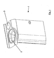
- Fig. 1 is a washbasin 1 shown with a sink 2 and a waste flap 3 attached next to which a (not explicitly shown) waste container is located.
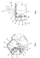
- FIG. 2 is a perspective view of the waste flap 3 from the inside of the vanity ago with a view obliquely above.
- This is a restoring device in the manner of a spring-damper unit 4 can be seen, in which a spring element and a parallel and speed-dependent damper element are integrated as a rechargeable energy storage.
- the spring-damper unit 4 is articulated on the one hand to a stationary bearing 5 on the vanity 1 and on the other hand to a bearing point 6 of the waste flap 3 in the vicinity of the folding axis 7.
- an opening device 8 is shown, with an electric motor 9 which is fixed axially parallel to the folding axis 7 on a bearing block 10 and on whose output shaft a winding spool 11 is arranged. Between the winding spool 11 and a holder 12 on the flap underside runs a drawstring 13, which is held in the shown closed position of the waste flap 3 taut.
- the waste flap 3 is shown in the closed position and the spring-damper unit 4, the reel spool 11 on the electric motor 9, and the tension band 13.
- an evaluation and control unit 14 is shown schematically, on the one hand to the electric motor 9 via an electric Connection 15 and via a further electrical connection 15 'is connected to the waste flap 3, which is here as a capacitor plate part of a non-contact proximity sensor 16.
- the proximity sensor 16 outputs an approximation signal to the evaluation and control unit 14 when the hand 17 shown approaches.
- the evaluation and control unit 14 controls the electric motor 9 for a predetermined time.
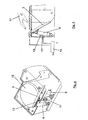
- the drawstring 13 is wound, whereby the waste flap 3 is pulled into its open position, which in the 4 and 5 is shown.
- the waste flap 3 thus releases a container opening 18 for the introduction of waste.
- the return spring is tensioned in the spring-damper unit 4, which is thereby shortened.
- the operating state is shown in which the spring-damper unit 4, the waste flap 3 is moved back to its original position or closed position, in which case about half way is covered here.
- the evaluation and control unit 14 has switched off the power supply to the electric motor 9 after the predetermined activation time.
- the electric motor 9 is dimensioned so strong that it opens the waste flap 3 against the restoring force of the spring-damper unit 4 with a bias of the return spring, but has only such a small inner reverse rotation in the de-energized state that a reverse rotation and thus a
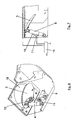
- Fig. 9 how out Fig. 9 can be seen then, as before, according to the prior art, the waste flap 3 with the hand 17 pressed down and opened. In this movement, only the tension band 13 is then relieved and settles in one or more loops, as in Fig. 8 is shown. At the same time with the opening movement by the hand 17, the return spring in the spring-damper unit 4 is tensioned. After dropping the waste and releasing the open waste flap 3, this is then shifted back by the spring-damper unit 4 back into the closed position, in which case the tension band 13 accordingly Fig. 2 is curious again.
Landscapes
- Engineering & Computer Science (AREA)
- Mechanical Engineering (AREA)
- Refuse Receptacles (AREA)
Description
- Die Erfindung betrifft eine Abfallklappe eines Abfallbehälters, insbesondere für ein Fahrzeug, höchst bevorzugt für ein Flugzeug, nach dem Oberbegriff des Patentanspruches 1.
- Allgemein bekannt ist beispielsweise ein Abfallbehälter, der in einen Waschtisch integriert ist, welcher in einem Fahrzeug, insbesondere in einem Flugzeug, in einem Bahnwaggon oder in einem Schiff eingebaut ist. In einer bekannten, gattungsgemäßen Anordnung ist dabei die Abfallklappe im oberen Randbereich der Behälteröffnung an einer Klappachse schwenkbar gelagert und von Hand nach innen gegen die Kraft einer Rückstelleinrichtung abklappbar um eine Einwurföffnung freizugeben. Die Rückstelleinrichtung ist zwischen einer ortsfesten Lagerstelle und einer Lagerstelle an der Abfallklappe angeordnet mit einem aufladbaren Energiespeicher, insbesondere einer Rückstellfeder verwendet. Durch die Handbetätigung der Abfallklappe in die Offenstellung wird der Energiespeicher aufgeladen bzw. die Rückstellfeder gespannt. Nach dem Loslassen der Abfallklappe wird diese dann durch die Rückstelleinrichtung aus der Offenstellung selbsttätig wieder in die Ausgangslage als Schließstellung zurückgestellt. Die Anordnung ist so dimensioniert, dass in der Schließstellung der Energiespeicher noch nicht ganz entladen ist bzw. eine Rückstellfeder noch nicht ganz entspannt ist, so dass die Abfallklappe von unten her am Rand der Behälteröffnung unter einer gewissen Vorspannung anliegt.
- Die bekannte Abfallklappe ist somit durch einen Druck der Hand von oben auf die federvorgespannte Abfallklappe zu betätigen. Durch eine solche zwangsläufige Berührung durch die Hand oder bereits durch Abfall, der in der Hand gehalten wird, ist eine solche Abfallklappe regelmäßig schon nach kurzem Gebrauch verschmutzt und verschmiert, so dass sie einerseits optisch unansehnlich wird und zudem hygienische Probleme bestehen.
- Aus der
EP 1 600 373 A2 ist bereits eine Abfallklappe bekannt, welche eine Rückstelleinrichtung mit einem aufladbaren Energiespeicher in Verbindung mit einem ansteuerbaren Elektromotor aufweist. Konkret funktioniert hier der Elektromotor als Dämpfer. Als Öffnungseinrichtung für die Abfallklappe ist hier ein starrer Hebel vorgesehen. Im stromlosen Zustand des Elektromotors können daher Klappergeräusche nicht mehr betriebssicher gedämpft bzw. reduziert werden. Zudem ist keine einfache Handbetätigung der Klappe beim Ausfall des Elektromotors möglich. - Aufgabe der Erfindung ist es daher, eine Abfallklappe bereitzustellen, bei der geräuscherzeugende Bewegungen, wie Vibrationen und Schwingungen, reduziert werden und welche auch bei einem Ausfall eines Elektromotors einer Öffnungseinrichtung betriebssicher funktioniert.
- Diese Aufgabe wird mit den Merkmalen des Anspruchs 1 gelöst.
- Gemäß Anspruch 1 ist eine Öffnungseinrichtung mit wenigstens einem bewegungsübertragenden Stellglied zwischen einer ortsfesten Halterung und einer Halterung an der Abfallklappe vorgesehen. Die Öffnungseinrichtung weist einen Elektromotor auf, der in einer der Öffnungsrichtung der Abfallklappe entsprechenden Drehrichtung ansteuerbar ist für eine Bewegung des Stellglieds und damit der Abfallklappe bis zu deren Offenstellung. Der Elektromotor ist dabei so stark dimensioniert, dass die Rückstelleinrichtung überdrückt und der darin enthaltene Energiespeicher aufgeladen wird. Damit ist dann die Behälteröffnung für einen Abfalleinwurf geöffnet. Anschließend wird die Ansteuerung des Elektromotors abgeschaltet. In diesem stromlosen Zustand des Elektromotors ist dessen mit dem wenigstens einen Stellglied gekoppelte Abtriebswelle durch Entladen des Energiespeichers rückdrehbar, so dass die Abfallklappe aus der Offenstellung in die Schließstellung sowie das Stellglied in die entsprechende Ausgangsstellung selbsttätig zurückgeführt wird.
- Weiter ist vorgesehen, dass die Abfallklappe in der Art eines einseitigen Hebels gelagert und angelenkt ist, wobei sie nach unten in die Behälteröffnung hinein öffenbar ist. Dadurch sind die Öffnungseinrichtung und die Rückstelleinrichtung in einem Behälterinnenbereich unterhalb der Abfallklappe angeordnet dergestalt, dass sich bei entsprechender Dimensionierung eine geeignete Kinematik ergibt. Als Stellglied wird erfindungsgemäß, ein Zugband verwendet, das einerseits mit der Halterung an der Abfallklappe und andererseits an einer mit der Abtriebswelle des Elektromotors verbundenen Wickelspule verbunden ist. Bei angesteuertem Elektromotor wird das Zugband für eine Zugöffnung der Abfallklappe aufgewickelt und bei nicht angesteuertem Elektromotor mittels der Rückstelleinrichtung wieder in eine gespannte Ausgangslage abgewickelt. Ein besonderer Vorteil des Zugbands besteht darin, dass die Abfallklappe jederzeit, beilspielsweise bei einem Ausfall der Öffnungseinrichtung auch unmittelbar von Hand geöffnet werden kann, wobei das Zugband lediglich entlastet wird und sich in Schlingen legt. Die selbsttätige Rückstellung in die Schließstellung der Abfallklappe ist dadurch nicht beeinträchtigt, da dabei das Zugband lediglich wieder in eine gespannte Position überführt wird.
- Die vorstehend beschriebene Rückdrehbarkeit der mit dem Stellglied gekoppelten Abtriebswelle des Elektromotors im stromlosen Zustand wird erfindungsgemäß einfach dadurch erreicht, dass der Elektromotor eine so kleine innere Rückdrehhemmung aufweist, dass der Elektromotor durch die Rückstellkraft des geladenen Energiespeichers bis in die Klappenschließstellung rückdrehbar ist.
- Des Weiteren ist erfindungsgemäß in der Rückstelleinrichtung als aufladbarer Energiespeicher eine Kombination einer Rückstellfeder mit einem dazu parallel und geschwindigkeitsproportional wirkenden Dämpfer vorgesehen. Durch diese Feder-Dämpfer-Kombination wird eine angenehm ruhige und gleichmäßige Rückverlagerung der Abfallklappe erreicht. Wenn nur eine Rückstellfeder ohne Dämpfer verwendet wird, kann dies bei betriebsbedingten Bewegungen, wie Vibrationen und Schwingungen dazu führen, dass die Abfallklappe vom Anlagerand leicht abhebt und klappert. Durch die Dämpferwirkung wird ein solches Klappern unterbunden. Die Rückstellfeder und der Dämpfer sind in einer Zylinder-Kolben-Einheit als Feder-Dämpfer-Einheit integriert, die einerseits an der Lagerstelle der Abfallklappe und andererseits an der ortsfesten Lagerstelle am Abfallbehälter gelenkig gelagert ist. Dadurch ergibt sich vorteilhaft eine kompakte Einheit, die wenig Bauraum beansprucht und bei guter Funktion wartungsfrei arbeitet.
- Für eine Öffnung der Abfallklappe ist es gemäß der Erfindung nicht mehr erforderlich diese unmittelbar mit der Hand gegen die Kraft der Rückstelleinrichtung zu Öffnen, sondern die Öffnung erfolgt durch eine Ansteuerung des Elektromotors selbsttätig. Die Ansteuerung kann dabei einfach durch einen Taster in der Nähe der Abfallklappe erfolgen, der ein Zeitglied für eine bestimmte Ansteuerzeit für eine Bestromung des Elektromotors aktiviert. Alternativ zu einem handbetätigbaren Taster können für eine Ansteuerung des Elektromotors auch andere an sich bekannte Ansteuerelemente, wie berührungslose Sensoren, Bewegungsmelder, Lichtschranken, Fußschalter etc. eingesetzt werden.
- Vorteilhaft ist damit die Abfallklappe regelmäßig bereits vor dem Einwurf des Abfalls geöffnet, so dass dieser nicht wie bisher üblich an der Abfallklappe vorbeistreift und dort zu Verschmutzungen und hygienischen Problemen führt. Ersichtlich liegt ein weiterer Vorteil in der bequemen einfachen Bedienung.
- In einer zweckmäßigen einbautechnisch günstigen Anordnung nach Anspruch 2 sind der Elektromotor achsparallel zur Klappachse an einem Lagerbock als ortsfester Halterung sowie die ortsfeste Lagerstelle der Rückstelleinrichtung in einem Behälterinnenbereich unterhalb der Klappachse angebracht. Die Lagerstelle der Rückstelleinrichtung an der Abfallklappe sowie die Halterung der Öffnungseinrichtung an der Abfallklappe sind dabei zur Abfallklappenmitte hin versetzt, wodurch eine gut beherrschbare Bewegungskinematik erreicht wird.
- Nach Anspruch 3 ist mit dem Elektromotor eine aktivierbare Steuerungseinheit verbunden, über die die Stromversorgung des Elektromotors für eine vorgegebene Zeit entsprechend einer Zeit für das Öffnen der Abfallklappe sowie einer zusätzlichen Zeit für das Offenhalten der Abfallklappe einschaltbar ist.
- In einer besonders bevorzugten Ausführungsform nach Anspruch 4 ist im Deckelteil und/oder der Steuerungseinheit der Abfallklappe ein Näherungssensor integriert, der bei einer Annäherung eines Gegenstands insbesondere bei einer Annäherung einer Hand ein Näherungssignal für eine unmittelbare oder mittelbare Ansteuerung der Öffnungseinrichtung erzeugt. Insbesondere soll nach Anspruch 5 das Näherungssignal einer Auswerte- und Steuerungseinrichtung zugeführt werden, die ab einer vorgegebenen Näherungsdistanz entsprechend einem bestimmten zugeordneten Näherungssignal den Elektromotor der Öffnungseinrichtung ansteuert.
- In einer konkreten Weiterbildung nach Anspruch 6 ist der Näherungssensor ein kapazitiver Sensor, wobei das Deckelteil der Abfallklappe selbst als Kondensatorplatte ausgebildet ist, wobei deren Kontaktierung mit der angeschlossenen Auswerte- und Steuerungseinrichtung bevorzugt über das Klappenachsenscharnier erfolgt.
- Besonders geeignet ist die erfindungsgemäße Anordnung des Abfallbehälters mit seiner Abfallklappe als Bestandteil eines Waschtisches für ein Fahrzeug, insbesondere für ein Flugzeug oder für einen Bahnwaggon oder für ein Schiff. Bei diesen Anwendungen ist zudem von besonderem Vorteil, dass die Abfallklappe stets geschlossen ist, insbesondere auch bei fehlender Stromversorgung und/oder anderweitig ausgefallenem Elektromotor, so dass in jedem Fall die Schließsicherheit gegeben ist und vom Abfallbehälter keine Feuergefahr oder unangenehme Geruchsbelästigung ausgeht. Zudem ist bei einer berührungslosen Klappenbetätigung ein hohes Maß an Hygiene gewährleistet.
- Anhand einer Zeichnung wird die Erfindung näher erläutert.
- Es zeigen:
- Fig. 1
- einen Teilausschnitt eines Waschtisches z. B. in einem Flugzeug mit einem eingebauten Abfallbehälter mit Abfallklappe,
- Fig. 2
- eine perspektivische Ansicht von unten auf die Abfallklappe mit Öffnungseinrichtung und Rückstelleinrichtung bei geschlossener Abfallklappe,
- Fig. 3
- eine Seitenansicht der Anordnung nach
Fig. 2 mit angedeuteter Wirkung eines in die Abfallklappe integrierten Näherungssensors, - Fig. 4
- die Anordnung nach
Fig. 2 jedoch mit durch die Öffnungseinrichtung geöffneter Abfallklappe, - Fig. 5
- eine Seitenansicht der Anordnung nach
Fig. 4 , - Fig. 6
- eine Anordnung entsprechend
Fig. 2 während der Klappenrückstellung mit teilweise geschlossener Abfallklappe, - Fig. 7
- eine Seitenansicht der Anordnung nach
Fig. 6 , - Fig. 8
- eine Anordnung
Fig. 2 mit einer durch direkte Handbetätigung teilweise geöffneter Abfallklappe ohne Darstellung der öffnungshand, und - Fig. 9
- eine Seitenansicht von
Fig. 8 mit einer Darstellung der Öffnungshand. - In
Fig. 1 ist ein Waschtisch 1 gezeigt mit einem Waschbecken 2 und einer daneben angebrachten Abfallklappe 3 unter der sich ein (nicht explizit dargestellter) Abfallbehälter befindet. - In
Fig. 2 ist eine perspektivische Darstellung auf die Abfallklappe 3 von der Innenseite des Waschtisches her mit einer Blickrichtung nach schräg oben dargestellt. Daraus ist eine Rückstelleinrichtung in der Art einer Feder-Dämpfer-Einheit 4 zu entnehmen, in der als aufladbarer Energiespeicher ein Federelement sowie ein parallel und geschwindigkeitsabhängiges Dämpferelement integriert sind. Die Feder-Dämpfer-Einheit 4 ist einerseits an einer ortsfesten Lagerstelle 5 am Waschtisch 1 und andererseits an einer Lagerstelle 6 der Abfallklappe 3 in der Nähe der Klappachse 7 gelenkig gelagert. - Weiter ist eine Öffnungseinrichtung 8 dargestellt, mit einem Elektromotor 9, der achsparallel zur Klappachse 7 an einem Lagerbock 10 befestigt ist und an dessen Abtriebswelle eine Wickelspule 11 angeordnet ist. Zwischen der Wickelspule 11 und einem Halter 12 an der Klappenunterseite verläuft ein Zugband 13, welches in der gezeigten Schließstellung der Abfallklappe 3 gestrafft gehalten ist.
- In der entsprechenden Seitendarstellung nach
Fig. 3 ist wiederum die Abfallklappe 3 in der Schließstellung gezeigt sowie die Feder-Dämpfer-Einheit 4, die Wickelspule 11 am Elektromotor 9, sowie das Zugband 13. Weiter ist schematisch eine Auswerte- und Steuerungseinheit 14 gezeigt, die einerseits mit dem Elektromotor 9 über eine elektrische Verbindung 15 und über eine weitere elektrische Verbindung 15' mit der Abfallklappe 3 verbunden ist, welche hier als Kondensatorplatte Teil eines berührungslos wirkenden Näherungssensors 16 ist. Der Näherungssensor 16 gibt bei Annäherung der gezeigten Hand 17 ein Näherungssignal an die Auswerte- und Steuerungseinheit 14 ab. - Die Funktion der in
Fig. 2 und inFig. 3 dargestellten Anordnung wird nun weiter unter Einbeziehung derFig. 4 bis 9 erläutert: - Bei der Annäherung der Hand 17 bis zu einer vorgegebenen Distanz an die Abfallklappe 3 steuert die Auswerte- und Steuerungseinheit 14 über eine vorgegebene Zeit den Elektromotor 9 an. Dadurch wird das Zugband 13 aufgewickelt, wodurch die Abfallklappe 3 in ihre Offenstellung gezogen wird, die in den
Fig. 4 und 5 gezeigt ist. Die Abfallklappe 3 gibt damit eine Behälteröffnung 18 für das Einwerfen von Abfall frei. Zugleich mit der Klappenöffnung wird die Rückstellfeder in der Feder-Dämpfer-Einheit 4 gespannt, die sich dadurch verkürzt. - In den
Fig. 6 und 7 ist der Betriebszustand gezeigt, bei dem die Feder-Dämpfer-Einheit 4 die Abfallklappe 3 wieder zurück in ihre Ausgangsstellung bzw. Schließstellung verlagert, wobei hier etwa der halbe Weg zurückgelegt ist. Für diese Rückverlagerung hat die Auswerte- und Steuerungseinheit 14 nach der vorgegebenen Ansteuerzeit die Stromversorgung zum Elektromotor 9 abgeschaltet. Der Elektromotor 9 ist so stark dimensioniert, dass er die Abfallklappe 3 gegen die Rückstellkraft der Feder-Dämpfer-Einheit 4 mit einer Vorspannung der Rückstellfeder öffnet, hat jedoch im stromlosen Zustand nur eine so kleine innere Rückdrehhemmung, dass ein Rückdrehen und damit eine - Rückverlagerung der Abfallklappe 3 durch die Federdämpfereinheit 4 erfolgt. Nach dem völligen Schließen der Abfallklappe 3 ist dann wiederum die in den
Fig. 2 und 3 gezeigte Schließstellung erreicht. - In den
Fig. 2 bis 7 ist das automatisierte Öffnen der Abfallklappe in Verbindung mit einer selbsttätigen Rückstellung gezeigt und erläutert. In denFig. 8 und 9 ist dagegen eine Notfallöffnung dargestellt, wenn beispielsweise der Näherungssensor 16 und/oder der Elektromotor 9 ausfällt. - Wie aus
Fig. 9 ersichtlich, kann dann wie bisher nach dem Stand der Technik die Abfallklappe 3 mit der Hand 17 nach unten gedrückt und geöffnet werden. Bei dieser Bewegung wird dann lediglich das Zugband 13 entlastet und legt sich in eine oder mehrere Schlingen, wie dies inFig. 8 dargestellt ist. Zugleich mit der Öffnungsbewegung durch die Hand 17 wird die Rückstellfeder in der Feder-Dämpfer-Einheit 4 gespannt. Nach dem Einwerfen des Abfalls und Loslassen der geöffneten Abfallklappe 3 wird dann diese durch die Feder-Dämpfer-Einheit 4 wieder in die Schließstellung zurückverlagert, wobei dann das Zugband 13 entsprechendFig. 2 wieder gespannt ist.
Claims (7)
- Abfallklappe (3) eines Abfallbehälters- die am Rand einer Behälteröffnung (18) an einer Klappachse (7) schwenkbar gelagert ist,- mit einer Rückstelleinrichtung (4) zwischen einer ortsfesten Lagerstelle (5) und einer Lagerstelle (6) an der Abfallklappe (3) mit einem aufladbaren Energiespeicher, wobei die Rückstelleinrichtung (4) die Abfallklappe (3) aus einer Offenstellung selbsttätig in eine die Behälteröffnung verschließende Schließstellung überführt, wobei- eine Öffnungseinrichtung (8) mit wenigstens einem bewegungs-übertragenden Stellglied (13) zwischen einer orstfesten Halterung (10) und einer Halterung (12) an der Abfallklappe (3) vorgesehen ist,- die Öffnungseinrichtung (8) zudem einen Elektromotor (9) aufweist, der in einer der Öffnungsrichtung der Abfallklappe (3) entsprechenden Drehrichtung für eine Stellgliedbewegung und damit für eine Klappenbewegung bis zur Offenstellung ansteuerbar ist, wobei zudem auch der Energiespeicher der Rückstelleinrichtung (4) aufgeladen wird, und- dass im nicht angesteuerten, stromlosen Zustand des Elektromotors (9) dessen mit dem wenigstens einen Stellglied (13) gekoppelte Abtriebswelle rückdrehbar ist und damit die Rückstelleinrichtung (4) durch Entladen des Energiespeichers die Abfallklappe (3) aus der Offenstellung in die Schließstellung sowie das Stellglied (13) in die entsprechende Ausgangsstellung zurückführt, und- die Abfallklappe (3) in der Art eines einseitigen Hebels nach unten in die Behälteröffnung (18) hinein öffenbar ist und die Öffnungseinrichtung (8) und Rückstelleinrichtung (4) in einem Bereich unterhalb der Abfallklappe (3) angeordnet sind,dadurch gekennzeichnet,- dass an der Abtriebswelle des Elektromotors (9) eine drehangetriebene Wickelspule (11) angeordnet ist,- dass als Stellglied ein Zugband (13) verwendet ist, das einerseits mit der Halterung (12) an der Abfallklappe (3) verbunden ist und andererseits an der Wickelspule (11) gehalten und bei angesteuertem Elektromotor (9) für eine Zugöffnung der Abfallklappe (3) aufwickelbar ist und bei nicht angesteuertem Elektromotor (9) mittels der Rückstelleinrichtung (4) wieder in eine gespannte Ausgangslage abwickelbar ist, wobei der Elektromotor (9) im nicht angesteuerten, stromlosen Zustand nur eine so kleine innere Rückdrehhemmung aufweist, dass der Elektromotor (9) wenigstens durch die Rückstellkraft des Energiespeichers der Rückstelleinrichtung (4) rückdrehbar ist, wobei in der Rückstell-einrichtung (4) als aufladbarer Energiespeicher eine Kombinationeine Rückstellfeder mit einem dazu parallel und geschwindigkeitsproportional wirkenden Dämpfer in einer Zylinder-Kolben-Einheit als Feder-Dämpfer-Einheit integriert sind, die einerseits an der Lagerstelle (6) an der Abfallklappe (3) und andererseits an der ortsfesten Lagerstelle (5) am Abfallbehälter gelenkig gelagert ist.
- Abfallklappe (3) nach Anspruch 1, dadurch gekennzeichnet, dass der Elektromotor (9) achsparallel zur Klappachse (7) an der
ortsfesten Halterung (10) sowie die ortsfeste Lagerstelle (5) der Rückstelleinrichtung (4) in einem Behälterinnenbereich unterhalb der Klappachse (7) angebracht sind, und
dass die Lagerstelle (6) der Rückstelleinrichtung (4) und Halterung (12) der Öffnungseinrichtung (8) an der Abfallklappe (3) dort zur Abfallklappenmitte hin versetzt liegen. - Abfallklappe (3) nach einem der Ansprüche 1 oder 2, dadurch gekennzeichnet, dass mit dem Elektromotor (9) eine aktivierbare Steuerungseinheit (14) verbunden ist, über die die Stromversorgung des Elektromotors (9) für eine vorgegebene Zeit entsprechend einer Zeit für das Öffnen der Abfallklappe (3) sowie einer zusätzlichen Zeit für das Offenhalten der Abfallklappe (3) einschaltbar ist.
- Abfallklappe (3) nach einem der Ansprüche 1 bis 3, dadurch gekennzeichnet, dass im Deckelteil und/oder der Steuerungseinheit der Abfallklappe (3) ein Näherungssensor (16) integriert ist, mit dem berührungslos eine Annäherung eines Gegenstands (17) erkennbar ist und ein Näherungssignal für eine unmittelbare oder mittelbare Ansteuerung der Öffnungseinrichtung (8) erzeugbar ist.
- Abfallklappe (3) nach Anspruch 4, dadurch gekennzeichnet, dass das Näherungssignal einer Auswerte- und Steuerungseinheit (14) zugeführt wird, die bei einer vorgegebenen Näherungsdistanz den Elektromotor (9) der Öffnungseinrichtung (8) ansteuert.
- Abfallklappe (3) nach Anspruch 4 oder 5, dadurch gekennzeichnet, dass der Näherungssensor (16) ein kapazitiver Sensor ist, wobei das Deckelteil der Abfallklappe (3) als Kondensatorplatte ausgebildet ist, deren Kontaktierung bevorzugt über das Klappachsenscharnier (7) erfolgt und der eine Auswerteelektronik nachgeschaltet ist.
- Abfallbehilter mit einer Abfallklappe (3) nach einem der Ansprüche 1 bis 6, dadurch gekennzeichnet, dass der Abfallbehälter Bestandteil eines Waschtisches (1) für ein Fahrzeug, insbesondere für ein Flugzeug oder für einen Bahnwaggon oder für ein Schiff ist.
Priority Applications (2)
| Application Number | Priority Date | Filing Date | Title |
|---|---|---|---|
| EP20080005322 EP2103554B1 (de) | 2008-03-20 | 2008-03-20 | Abfallklappe eines Abfallbehälters, insbesondere für ein Fahrzeug |
| ES08005322T ES2393137T3 (es) | 2008-03-20 | 2008-03-20 | Tapa para residuos de un contenedor de residuos, en particular para un vehículo |
Applications Claiming Priority (1)
| Application Number | Priority Date | Filing Date | Title |
|---|---|---|---|
| EP20080005322 EP2103554B1 (de) | 2008-03-20 | 2008-03-20 | Abfallklappe eines Abfallbehälters, insbesondere für ein Fahrzeug |
Publications (2)
| Publication Number | Publication Date |
|---|---|
| EP2103554A1 EP2103554A1 (de) | 2009-09-23 |
| EP2103554B1 true EP2103554B1 (de) | 2012-08-29 |
Family
ID=39673008
Family Applications (1)
| Application Number | Title | Priority Date | Filing Date |
|---|---|---|---|
| EP20080005322 Not-in-force EP2103554B1 (de) | 2008-03-20 | 2008-03-20 | Abfallklappe eines Abfallbehälters, insbesondere für ein Fahrzeug |
Country Status (2)
| Country | Link |
|---|---|
| EP (1) | EP2103554B1 (de) |
| ES (1) | ES2393137T3 (de) |
Cited By (1)
| Publication number | Priority date | Publication date | Assignee | Title |
|---|---|---|---|---|
| EP3919712A1 (de) * | 2020-06-01 | 2021-12-08 | Soluciones Conceptuales E Innovacion S.L. | Vorrichtung zum automatischen öffnen und schliessen eines tores |
Families Citing this family (3)
| Publication number | Priority date | Publication date | Assignee | Title |
|---|---|---|---|---|
| FR2960586B1 (fr) * | 2010-05-28 | 2015-04-24 | Cuivrinox | Dispositif de manoeuvre d'un volet |
| CN108529091A (zh) * | 2018-05-07 | 2018-09-14 | 深圳市粤能环保科技有限公司 | 回收箱 |
| CN109230090B (zh) * | 2018-09-20 | 2023-09-01 | 上海拓牛智能科技有限公司 | 一种桶盖缓降装置、智能垃圾桶及其控制方法 |
Family Cites Families (4)
| Publication number | Priority date | Publication date | Assignee | Title |
|---|---|---|---|---|
| US4981275A (en) * | 1990-04-02 | 1991-01-01 | Sheu Miin Shiou | Photoelectric garbage bin |
| CA2384483C (en) * | 2002-05-01 | 2010-07-20 | Biochem Environmental Solutions Inc. | Automatic lid opening and closing system for a waste container |
| JP4245511B2 (ja) | 2004-05-24 | 2009-03-25 | 株式会社ジャムコ | 航空機の化粧室のごみ箱用蓋自動開閉装置 |
| US20070145057A1 (en) * | 2005-12-23 | 2007-06-28 | Greg Nance | Automatic countertop access port and method of use thereof |
-
2008
- 2008-03-20 ES ES08005322T patent/ES2393137T3/es active Active
- 2008-03-20 EP EP20080005322 patent/EP2103554B1/de not_active Not-in-force
Cited By (1)
| Publication number | Priority date | Publication date | Assignee | Title |
|---|---|---|---|---|
| EP3919712A1 (de) * | 2020-06-01 | 2021-12-08 | Soluciones Conceptuales E Innovacion S.L. | Vorrichtung zum automatischen öffnen und schliessen eines tores |
Also Published As
| Publication number | Publication date |
|---|---|
| ES2393137T3 (es) | 2012-12-18 |
| EP2103554A1 (de) | 2009-09-23 |
Similar Documents
| Publication | Publication Date | Title |
|---|---|---|
| DE69909204T2 (de) | Verbessertes elektrisches Schloss für eine Kraftfahrzeugtür | |
| EP1982030B1 (de) | Verfahren und vorrichtung zum steuern der schliessbewegung eines karosseriebauteils für fahrzeuge | |
| EP2032783B1 (de) | Betätigungsvorrichtung | |
| DE102017214174A1 (de) | Kraft-Türpräsentator mit Verriegelungsmerkmal | |
| EP3132716B1 (de) | Vorrichtung zum bewegen eines bewegbaren möbelteils und möbel | |
| AT12708U1 (de) | Möbelantrieb | |
| EP2103554B1 (de) | Abfallklappe eines Abfallbehälters, insbesondere für ein Fahrzeug | |
| DE202018105971U1 (de) | Intelligenter Mülleimer | |
| DE20016339U1 (de) | Müllbehälter mit einem mit einer interaktiven Pedalvorrichtung verbundenen Klappdeckel | |
| DE112007002274T5 (de) | Schubladenvorrichtung mit Hilfseinrichtung | |
| EP2040580B1 (de) | Vorrichtung zum bewegen von zueinander bewegbaren möbelteilen und möbel | |
| WO2014114514A1 (de) | Beschleunigungsvorrichtung für bewegbare möbel- oder haushaltsgeräteteile | |
| DE10256348B4 (de) | Laderaumabdeckung für ein Kraftfahrzeug | |
| EP2364614B1 (de) | Ausstoßvorrichtung für bewegbare Möbelteile | |
| DE102010054658B4 (de) | Funkschloss für Mülltonnen | |
| DE202006021048U1 (de) | Ausstoßvorrichtung für ein bewegbares Möbelteil | |
| EP1848652A1 (de) | Abfallsammler | |
| DE69907356T2 (de) | Vereinfachtes Schloss für eine Kraftfahrzeugtür | |
| DE102017201958B4 (de) | Antrieb für einen Tür- oder Fensterflügel | |
| AT508228A1 (de) | Vorrichtung und verfahren zum wahlweise zumindest teilweise automatischen öffnen bzw. schliessen einer tür | |
| DE202006006190U1 (de) | Möbel | |
| DE102012201013B3 (de) | Vorrichtung zum Öffnen und Schließen von Türen mit dem Fuß | |
| DE19947203A1 (de) | Vorrichtung zur Arretierung einer Tür | |
| DE102005004571A1 (de) | Kraftunterstütztes Fahrzeugscharnier | |
| DE102007035803B4 (de) | Kraftfahrzeug mit wenigstens einer zum Besteigen oder Verlassen des Innenraums öffen- und schließbaren Türe |
Legal Events
| Date | Code | Title | Description |
|---|---|---|---|
| PUAI | Public reference made under article 153(3) epc to a published international application that has entered the european phase |
Free format text: ORIGINAL CODE: 0009012 |
|
| AK | Designated contracting states |
Kind code of ref document: A1 Designated state(s): AT BE BG CH CY CZ DE DK EE ES FI FR GB GR HR HU IE IS IT LI LT LU LV MC MT NL NO PL PT RO SE SI SK TR |
|
| AX | Request for extension of the european patent |
Extension state: AL BA MK RS |
|
| 17P | Request for examination filed |
Effective date: 20100115 |
|
| 17Q | First examination report despatched |
Effective date: 20100304 |
|
| AKX | Designation fees paid |
Designated state(s): AT BE BG CH CY CZ DE DK EE ES FI FR GB GR HR HU IE IS IT LI LT LU LV MC MT NL NO PL PT RO SE SI SK TR |
|
| GRAP | Despatch of communication of intention to grant a patent |
Free format text: ORIGINAL CODE: EPIDOSNIGR1 |
|
| GRAS | Grant fee paid |
Free format text: ORIGINAL CODE: EPIDOSNIGR3 |
|
| GRAA | (expected) grant |
Free format text: ORIGINAL CODE: 0009210 |
|
| AK | Designated contracting states |
Kind code of ref document: B1 Designated state(s): AT BE BG CH CY CZ DE DK EE ES FI FR GB GR HR HU IE IS IT LI LT LU LV MC MT NL NO PL PT RO SE SI SK TR |
|
| REG | Reference to a national code |
Ref country code: GB Ref legal event code: FG4D Free format text: NOT ENGLISH |
|
| REG | Reference to a national code |
Ref country code: CH Ref legal event code: EP |
|
| REG | Reference to a national code |
Ref country code: AT Ref legal event code: REF Ref document number: 572942 Country of ref document: AT Kind code of ref document: T Effective date: 20120915 |
|
| REG | Reference to a national code |
Ref country code: IE Ref legal event code: FG4D Free format text: LANGUAGE OF EP DOCUMENT: GERMAN |
|
| REG | Reference to a national code |
Ref country code: DE Ref legal event code: R096 Ref document number: 502008008039 Country of ref document: DE Effective date: 20121025 |
|
| REG | Reference to a national code |
Ref country code: CH Ref legal event code: NV Representative=s name: ABACUS PATENTANWAELTE KLOCKE SPAETH BARTH, CH |
|
| REG | Reference to a national code |
Ref country code: NL Ref legal event code: T3 |
|
| REG | Reference to a national code |
Ref country code: ES Ref legal event code: FG2A Ref document number: 2393137 Country of ref document: ES Kind code of ref document: T3 Effective date: 20121218 |
|
| REG | Reference to a national code |
Ref country code: LT Ref legal event code: MG4D Effective date: 20120829 |
|
| PG25 | Lapsed in a contracting state [announced via postgrant information from national office to epo] |
Ref country code: NO Free format text: LAPSE BECAUSE OF FAILURE TO SUBMIT A TRANSLATION OF THE DESCRIPTION OR TO PAY THE FEE WITHIN THE PRESCRIBED TIME-LIMIT Effective date: 20121129 Ref country code: IS Free format text: LAPSE BECAUSE OF FAILURE TO SUBMIT A TRANSLATION OF THE DESCRIPTION OR TO PAY THE FEE WITHIN THE PRESCRIBED TIME-LIMIT Effective date: 20121229 Ref country code: FI Free format text: LAPSE BECAUSE OF FAILURE TO SUBMIT A TRANSLATION OF THE DESCRIPTION OR TO PAY THE FEE WITHIN THE PRESCRIBED TIME-LIMIT Effective date: 20120829 Ref country code: HR Free format text: LAPSE BECAUSE OF FAILURE TO SUBMIT A TRANSLATION OF THE DESCRIPTION OR TO PAY THE FEE WITHIN THE PRESCRIBED TIME-LIMIT Effective date: 20120829 Ref country code: LT Free format text: LAPSE BECAUSE OF FAILURE TO SUBMIT A TRANSLATION OF THE DESCRIPTION OR TO PAY THE FEE WITHIN THE PRESCRIBED TIME-LIMIT Effective date: 20120829 |
|
| PG25 | Lapsed in a contracting state [announced via postgrant information from national office to epo] |
Ref country code: PT Free format text: LAPSE BECAUSE OF FAILURE TO SUBMIT A TRANSLATION OF THE DESCRIPTION OR TO PAY THE FEE WITHIN THE PRESCRIBED TIME-LIMIT Effective date: 20121231 Ref country code: SE Free format text: LAPSE BECAUSE OF FAILURE TO SUBMIT A TRANSLATION OF THE DESCRIPTION OR TO PAY THE FEE WITHIN THE PRESCRIBED TIME-LIMIT Effective date: 20120829 Ref country code: SI Free format text: LAPSE BECAUSE OF FAILURE TO SUBMIT A TRANSLATION OF THE DESCRIPTION OR TO PAY THE FEE WITHIN THE PRESCRIBED TIME-LIMIT Effective date: 20120829 Ref country code: GR Free format text: LAPSE BECAUSE OF FAILURE TO SUBMIT A TRANSLATION OF THE DESCRIPTION OR TO PAY THE FEE WITHIN THE PRESCRIBED TIME-LIMIT Effective date: 20121130 Ref country code: LV Free format text: LAPSE BECAUSE OF FAILURE TO SUBMIT A TRANSLATION OF THE DESCRIPTION OR TO PAY THE FEE WITHIN THE PRESCRIBED TIME-LIMIT Effective date: 20120829 |
|
| PG25 | Lapsed in a contracting state [announced via postgrant information from national office to epo] |
Ref country code: DK Free format text: LAPSE BECAUSE OF FAILURE TO SUBMIT A TRANSLATION OF THE DESCRIPTION OR TO PAY THE FEE WITHIN THE PRESCRIBED TIME-LIMIT Effective date: 20120829 Ref country code: CZ Free format text: LAPSE BECAUSE OF FAILURE TO SUBMIT A TRANSLATION OF THE DESCRIPTION OR TO PAY THE FEE WITHIN THE PRESCRIBED TIME-LIMIT Effective date: 20120829 Ref country code: RO Free format text: LAPSE BECAUSE OF FAILURE TO SUBMIT A TRANSLATION OF THE DESCRIPTION OR TO PAY THE FEE WITHIN THE PRESCRIBED TIME-LIMIT Effective date: 20120829 Ref country code: EE Free format text: LAPSE BECAUSE OF FAILURE TO SUBMIT A TRANSLATION OF THE DESCRIPTION OR TO PAY THE FEE WITHIN THE PRESCRIBED TIME-LIMIT Effective date: 20120829 |
|
| PG25 | Lapsed in a contracting state [announced via postgrant information from national office to epo] |
Ref country code: PL Free format text: LAPSE BECAUSE OF FAILURE TO SUBMIT A TRANSLATION OF THE DESCRIPTION OR TO PAY THE FEE WITHIN THE PRESCRIBED TIME-LIMIT Effective date: 20120829 Ref country code: SK Free format text: LAPSE BECAUSE OF FAILURE TO SUBMIT A TRANSLATION OF THE DESCRIPTION OR TO PAY THE FEE WITHIN THE PRESCRIBED TIME-LIMIT Effective date: 20120829 Ref country code: CY Free format text: LAPSE BECAUSE OF FAILURE TO SUBMIT A TRANSLATION OF THE DESCRIPTION OR TO PAY THE FEE WITHIN THE PRESCRIBED TIME-LIMIT Effective date: 20120829 |
|
| PLBE | No opposition filed within time limit |
Free format text: ORIGINAL CODE: 0009261 |
|
| STAA | Information on the status of an ep patent application or granted ep patent |
Free format text: STATUS: NO OPPOSITION FILED WITHIN TIME LIMIT |
|
| PG25 | Lapsed in a contracting state [announced via postgrant information from national office to epo] |
Ref country code: BG Free format text: LAPSE BECAUSE OF FAILURE TO SUBMIT A TRANSLATION OF THE DESCRIPTION OR TO PAY THE FEE WITHIN THE PRESCRIBED TIME-LIMIT Effective date: 20121129 |
|
| 26N | No opposition filed |
Effective date: 20130530 |
|
| REG | Reference to a national code |
Ref country code: DE Ref legal event code: R097 Ref document number: 502008008039 Country of ref document: DE Effective date: 20130530 |
|
| BERE | Be: lapsed |
Owner name: EME ELEKTRO-METALL EXPORT G.M.B.H. Effective date: 20130331 |
|
| PG25 | Lapsed in a contracting state [announced via postgrant information from national office to epo] |
Ref country code: MC Free format text: LAPSE BECAUSE OF NON-PAYMENT OF DUE FEES Effective date: 20130331 |
|
| REG | Reference to a national code |
Ref country code: IE Ref legal event code: MM4A |
|
| PG25 | Lapsed in a contracting state [announced via postgrant information from national office to epo] |
Ref country code: IE Free format text: LAPSE BECAUSE OF NON-PAYMENT OF DUE FEES Effective date: 20130320 Ref country code: BE Free format text: LAPSE BECAUSE OF NON-PAYMENT OF DUE FEES Effective date: 20130331 |
|
| REG | Reference to a national code |
Ref country code: AT Ref legal event code: MM01 Ref document number: 572942 Country of ref document: AT Kind code of ref document: T Effective date: 20130320 |
|
| PG25 | Lapsed in a contracting state [announced via postgrant information from national office to epo] |
Ref country code: MT Free format text: LAPSE BECAUSE OF FAILURE TO SUBMIT A TRANSLATION OF THE DESCRIPTION OR TO PAY THE FEE WITHIN THE PRESCRIBED TIME-LIMIT Effective date: 20120829 |
|
| PG25 | Lapsed in a contracting state [announced via postgrant information from national office to epo] |
Ref country code: AT Free format text: LAPSE BECAUSE OF NON-PAYMENT OF DUE FEES Effective date: 20130320 |
|
| PG25 | Lapsed in a contracting state [announced via postgrant information from national office to epo] |
Ref country code: TR Free format text: LAPSE BECAUSE OF FAILURE TO SUBMIT A TRANSLATION OF THE DESCRIPTION OR TO PAY THE FEE WITHIN THE PRESCRIBED TIME-LIMIT Effective date: 20120829 |
|
| PG25 | Lapsed in a contracting state [announced via postgrant information from national office to epo] |
Ref country code: HU Free format text: LAPSE BECAUSE OF FAILURE TO SUBMIT A TRANSLATION OF THE DESCRIPTION OR TO PAY THE FEE WITHIN THE PRESCRIBED TIME-LIMIT; INVALID AB INITIO Effective date: 20080320 Ref country code: LU Free format text: LAPSE BECAUSE OF NON-PAYMENT OF DUE FEES Effective date: 20130320 |
|
| REG | Reference to a national code |
Ref country code: FR Ref legal event code: PLFP Year of fee payment: 9 |
|
| REG | Reference to a national code |
Ref country code: FR Ref legal event code: PLFP Year of fee payment: 10 |
|
| REG | Reference to a national code |
Ref country code: FR Ref legal event code: PLFP Year of fee payment: 11 |
|
| PGFP | Annual fee paid to national office [announced via postgrant information from national office to epo] |
Ref country code: GB Payment date: 20180314 Year of fee payment: 11 |
|
| PGFP | Annual fee paid to national office [announced via postgrant information from national office to epo] |
Ref country code: NL Payment date: 20180426 Year of fee payment: 11 |
|
| PGFP | Annual fee paid to national office [announced via postgrant information from national office to epo] |
Ref country code: ES Payment date: 20180402 Year of fee payment: 11 Ref country code: CH Payment date: 20180525 Year of fee payment: 11 |
|
| PGFP | Annual fee paid to national office [announced via postgrant information from national office to epo] |
Ref country code: IT Payment date: 20180329 Year of fee payment: 11 |
|
| PGFP | Annual fee paid to national office [announced via postgrant information from national office to epo] |
Ref country code: FR Payment date: 20190328 Year of fee payment: 12 |
|
| PGFP | Annual fee paid to national office [announced via postgrant information from national office to epo] |
Ref country code: DE Payment date: 20190531 Year of fee payment: 12 |
|
| REG | Reference to a national code |
Ref country code: CH Ref legal event code: PL |
|
| REG | Reference to a national code |
Ref country code: NL Ref legal event code: MM Effective date: 20190401 |
|
| GBPC | Gb: european patent ceased through non-payment of renewal fee |
Effective date: 20190320 |
|
| PG25 | Lapsed in a contracting state [announced via postgrant information from national office to epo] |
Ref country code: NL Free format text: LAPSE BECAUSE OF NON-PAYMENT OF DUE FEES Effective date: 20190401 Ref country code: LI Free format text: LAPSE BECAUSE OF NON-PAYMENT OF DUE FEES Effective date: 20190331 Ref country code: GB Free format text: LAPSE BECAUSE OF NON-PAYMENT OF DUE FEES Effective date: 20190320 Ref country code: CH Free format text: LAPSE BECAUSE OF NON-PAYMENT OF DUE FEES Effective date: 20190331 |
|
| PG25 | Lapsed in a contracting state [announced via postgrant information from national office to epo] |
Ref country code: IT Free format text: LAPSE BECAUSE OF NON-PAYMENT OF DUE FEES Effective date: 20190320 |
|
| REG | Reference to a national code |
Ref country code: ES Ref legal event code: FD2A Effective date: 20200727 |
|
| REG | Reference to a national code |
Ref country code: DE Ref legal event code: R119 Ref document number: 502008008039 Country of ref document: DE |
|
| PG25 | Lapsed in a contracting state [announced via postgrant information from national office to epo] |
Ref country code: ES Free format text: LAPSE BECAUSE OF NON-PAYMENT OF DUE FEES Effective date: 20190321 |
|
| PG25 | Lapsed in a contracting state [announced via postgrant information from national office to epo] |
Ref country code: FR Free format text: LAPSE BECAUSE OF NON-PAYMENT OF DUE FEES Effective date: 20200331 Ref country code: DE Free format text: LAPSE BECAUSE OF NON-PAYMENT OF DUE FEES Effective date: 20201001 |