EP2103748A2 - Robinet à large dispersion, caché, et son procédé d'installation - Google Patents
Robinet à large dispersion, caché, et son procédé d'installation Download PDFInfo
- Publication number
- EP2103748A2 EP2103748A2 EP20080006592 EP08006592A EP2103748A2 EP 2103748 A2 EP2103748 A2 EP 2103748A2 EP 20080006592 EP20080006592 EP 20080006592 EP 08006592 A EP08006592 A EP 08006592A EP 2103748 A2 EP2103748 A2 EP 2103748A2
- Authority
- EP
- European Patent Office
- Prior art keywords
- housing
- threaded
- main body
- defining
- nut
- Prior art date
- Legal status (The legal status is an assumption and is not a legal conclusion. Google has not performed a legal analysis and makes no representation as to the accuracy of the status listed.)
- Withdrawn
Links
- 238000000034 method Methods 0.000 title description 15
- 230000006835 compression Effects 0.000 claims abstract description 48
- 238000007906 compression Methods 0.000 claims abstract description 48
- 238000009434 installation Methods 0.000 claims description 19
- 238000005242 forging Methods 0.000 abstract description 4
- 244000261422 Lysimachia clethroides Species 0.000 description 16
- 210000003660 reticulum Anatomy 0.000 description 13
- 238000012856 packing Methods 0.000 description 7
- 238000007789 sealing Methods 0.000 description 6
- 230000000284 resting effect Effects 0.000 description 5
- XLYOFNOQVPJJNP-UHFFFAOYSA-N water Substances O XLYOFNOQVPJJNP-UHFFFAOYSA-N 0.000 description 5
- 230000004323 axial length Effects 0.000 description 2
- 238000004891 communication Methods 0.000 description 2
- 239000012530 fluid Substances 0.000 description 2
- 238000011900 installation process Methods 0.000 description 2
- 239000007788 liquid Substances 0.000 description 2
- 238000004519 manufacturing process Methods 0.000 description 2
- 239000000463 material Substances 0.000 description 2
- 238000012986 modification Methods 0.000 description 2
- 230000004048 modification Effects 0.000 description 2
- 238000009428 plumbing Methods 0.000 description 1
- 239000007921 spray Substances 0.000 description 1
Images






Classifications
-
- E—FIXED CONSTRUCTIONS
- E03—WATER SUPPLY; SEWERAGE
- E03C—DOMESTIC PLUMBING INSTALLATIONS FOR FRESH WATER OR WASTE WATER; SINKS
- E03C1/00—Domestic plumbing installations for fresh water or waste water; Sinks
- E03C1/02—Plumbing installations for fresh water
- E03C1/04—Water-basin installations specially adapted to wash-basins or baths
- E03C1/0401—Fixing a tap to the sanitary appliance or to an associated mounting surface, e.g. a countertop
-
- Y—GENERAL TAGGING OF NEW TECHNOLOGICAL DEVELOPMENTS; GENERAL TAGGING OF CROSS-SECTIONAL TECHNOLOGIES SPANNING OVER SEVERAL SECTIONS OF THE IPC; TECHNICAL SUBJECTS COVERED BY FORMER USPC CROSS-REFERENCE ART COLLECTIONS [XRACs] AND DIGESTS
- Y10—TECHNICAL SUBJECTS COVERED BY FORMER USPC
- Y10T—TECHNICAL SUBJECTS COVERED BY FORMER US CLASSIFICATION
- Y10T137/00—Fluid handling
- Y10T137/9464—Faucets and spouts
Definitions
- the time to install a conventional concealed, wide spread faucet is about 15 minutes for an expert plumber and about 30 to 45 minutes for an unskilled helper.
- a conventional concealed, wide spread faucet is unpacked from the shipping carton, before the plumber can begin to install the faucet in the sink, the plumber first must uninstall the valve cartridges and all above deck nuts, washers, etc., which are generally on the faucet in the condition in which it is received from the factory.
- the plumber must re-install the valve cartridges, and upon doing so the installer could reverse the hot and cold valves, cause a leak path during re-installation of the valve cartridges and/or damage the valve cartridges.
- Still other similar concealed, wide spread faucets require the installer to connect conduits leading from each of the valves to the spigot that is disposed between the valve housings.
- the user Upon replacing a gooseneck with built-in flow control device, the user might not realize that the replacement gooseneck must be the type with built-in flow control device until after the user has installed a gooseneck without a built-in flow control device. Or the new gooseneck might have a built-in flow control device with a different flow rating that is unsuitable for the end use.
- Another disadvantage of providing the cartridge with a built-in flow control device is the inability to control the overall flow out of the gooseneck. For instance, if the flow needs to be two gallons per minute and each cartridge is provided with a built-in flow control device rated at one gallon per minute, then the overall flow only becomes the desired two gallons per minute when both cartridges are open. When only one cartridge is open (hot or cold), then the overall flow out of the gooseneck is only one gallon per minute. Similarly, if each cartridge is provided with a built-in flow control device rated at two gallons per minute, the overall flow out of the gooseneck becomes the desired two gallons per minute when cartridge is open, but up to four gallons per minute as the other cartridge is opened.
- a concealed, wide spread faucet for installation in a sink comprises a main body, which desirably is formed as a unitary forging.
- the valve seats and valves desirably are factory installed in the valve housings, which desirably are permanently pre-connected to the main body at the factory. Only the center shank remains to be connected to the central receptacle of the main body by the installer using a compression nut during the installation.
- the central receptacle is configured to carry the compression nut, which is configured to receive thereon and carry a central flange nut that is used to secure the center shank to the sink deck.
- a hanger is provided to hold the main body in place to the sink deck with the compression nut carrying the central flange nut and aligned in position to receive the center shank and guide the center shank into the central receptacle of the main body.
- a C-washer Configured to engage each of the valve housings of the main body, a C-washer is provided to be inserted by the installer between the respective valve housing and the upper surface of the sink deck to hold the valve housings above the sink deck and the main body below the sink deck while automatically leveling the faucet with respect to the sink deck.
- the hanger can be disengaged from the sink deck and the main body because the C-washers enable the installer to tighten the threaded flange nuts beneath the sink deck to secure the valve housings to the sink deck.
- the center shank is connected at the factory to a deck flange nut, and the resulting structure can be inserted into the main body from above the sink deck with the deck flange nut resting against the upper surface of the sink deck.
- the center shank can be secured to the sink deck by the central flange nut carried on the compression nut beneath the sink deck and the deck flange nut above the sink deck.
- the compression nut can engage the main body so as to compression fit the center shank to the main body in a watertight seal.
- the installer begins by hooking the hanger to the main body with the compression nut loosely connected to the main body and the central flange nut carried on the top of the compression nut.
- the installer moves beneath the sink deck the hanger and main body carrying the compression nut and the central flange nut. From beneath the sink deck, the installer pushes the hanger through the center hole in the sink deck to hang the main body from the sink deck with the two valve housings projecting through the two outlying holes in the sink deck.
- the installer inserts the C-washers to hold the valve housings in place above the sink deck and thereby levels the faucet assembly.
- the installer disengages the hanger and pushes it beneath the sink deck.
- the installer inserts the center shank through the middle hole in the sink deck and into the central receptacle of the main body so that the skirt of the deck flange rests atop the sink deck.
- the installer From beneath the sink deck, the installer tightens the two flange nuts to secure the two valve housings to the sink deck and tightens the center flange nut to secure the center shank to the sink deck. From beneath the sink deck, the installer tightens the compression nut to secure the center shank to the main body. Since the compression nut is adjustable, it should be the last nut to be tightened in order to ensure that all of the other connections are rigid. From beneath the sink deck, the installer makes the appropriate connections to attach the water supply lines to the faucet.
- FIG. 1 A presently preferred embodiment of the concealed, wide spread faucet is shown in Fig. 1 in an elevated unassembled perspective view and is indicated generally by the numeral 10.
- the wide spread faucet 10 desirably includes a main body 11 that is formed as a unitary structure and includes on one end thereof a first housing 11a and on the other end thereof a second housing 11b.
- the main body 11 includes a first branch 11c connected at one end thereof to the first housing 11a.
- a second branch 11d is connected at one end thereof to the second housing 11b.
- each of the first branch 11c and the second branch 11d defines a respective hollow passage 11e, 11f internally thereof and communicating with, respectively, first housing 11a and second housing 11 b.
- the main body 10 further defines a central receptacle 11g disposed between the first housing 11a and the second housing 11b.
- the central receptacle 11g is connected to the other end of first branch 11c and to the other end of second branch 11d.
- the first housing 11a is disposed in fluid communication with the second housing 11b via the first passage 11e, the central receptacle 11g and the second passage 11f.
- the central receptacle 11g is disposed midway between the first housing 11a and the second housing 11b, but could be disposed closer to one or the other of the housings, as desired.
- the first branch 11c and the second branch 11d are elongating in generally a straight line, but could be disposed at an angle with respect to one another, if desired.
- the main body 11 desirably is formed of a single unitary forging that is molded with the desired exterior dimensions and that is drilled to provide the desired interior dimensions.
- the user need not connect the first branch 11c to the first housing 11a and to the central receptacle 11g.
- the user need to connect the second branch 11d to the second housing 11b and to the central receptacle 11g.
- this extra assembly is avoided and the installation process is simplified.
- forming the main body 11 as a unitary structure avoids four possible interfaces where connections otherwise would need to be made. Thus, leaks at these four connections are avoided. Leaks are thereby avoided between the first branch 11c and each of the first housing 11a and the central receptacle 11g, and similarly between the second branch 11d and each of the second housing 11b and the central receptacle 11g.
- a first set screw 28a is configured to be threaded into a threaded opening defined through the first housing 11a.
- a second set screw 28b is configured to be threaded into an opening defined through the second housing 11b.
- the set screws 28a, 28b seal off the holes that were used to drill through the forging that desirably is used to make the main body 11, respectively, the first passage 11e in the first branch 11c and the second passage 11f in the second branch 11d.
- the central receptacle 11g defines an upper projection 11h that is cylindrical and desirably defines an external surface 11i having a plurality of screw threads thereon. As shown in Fig. 5 , the central receptacle 11g further defines a lower projection 11j that is cylindrical and desirably defines an internally threaded surface 11 k. As shown in Fig. 5 , the central receptacle 11g with its upper projection 11h and lower projection 11j define internally thereof a central channel 11l. In an alternative embodiment, the central channel 11l is open only on the end defined by the upper projection 11h and is sealed at the end defined by the lower projection 11j. However, in the embodiment shown in Fig.
- the faucet 10 is provided with the hot and cold valves already assembled and tested at the factory and held in a pair of valve housings that are connected to the first and second housings 11a, 11b of the main body 11.
- Each of the first housing 11a and the second housing 11b is configured to contain at least part of a valve that includes both a valve cartridge and a valve cartridge seat.
- a first valve housing includes a first threaded sleeve 12a that is configured to be connected at one end thereof to the first housing 11a.
- a second valve housing includes a second threaded sleeve 12b that is configured to be connected at one end thereof to the second housing 11b.
- Each first sleeve 12a and second sleeve 12b is desirably cylindrical in shape and configured to receive internally therein a respective first and second valve cartridge.
- the interior surface of the bottom end of the first threaded sleeve 12a is defined by a screw threaded surface 12c that selectively permits detachable screwing attachment of the first sleeve 12a to the first housing 11a via the externally threaded surface 11m of the upwardly projecting portion of the first housing 11a.
- a screw threaded surface 12c that selectively permits detachable screwing attachment of the first sleeve 12a to the first housing 11a via the externally threaded surface 11m of the upwardly projecting portion of the first housing 11a.
- the interior surface of the bottom end of the second threaded sleeve 12b is defined by a screw threaded surface 12d that selectively permits detachable screwing attachment of the second sleeve 12b to the second housing 11b via the externally threaded surface 11n of the upwardly projecting portion of the second housing 11b.
- each of the first and second threaded sleeves 12a, 12b is permanently connected at the factory in watertight fashion to its respective first housing 11a and second housing 11b.
- the first housing 11a and the first sleeve 12a can be provided as a unitary structure that avoids the need for the connection via the screwing engagement of the externally threaded surface 11 m to the interior threaded surface 12c of the first sleeve12a.
- a similar unitary structural arrangement can be implemented for the second housing 11b and the second sleeve 12b.
- the exterior surface of the first sleeve 12a is desirably characterized by three different sections, a lower section, an intermediate section and an upper section.
- the lower section is defined by a threaded exterior surface 12e, and of the three sections the lower section has the largest external diameter and the longest axial length.
- the intermediate section 12f is the section having the smallest axial length and is also the section with the smallest external diameter and has a smooth external surface without any threaded portion.
- the upper section has a threaded external surface 12g and has an external diameter intermediate the external diameter of the intermediate section 12f and the external diameter of the lower section 12e. Moreover, the leading edge of the radially extending threads of the upper section 12g defines a slight lip above the intermediate section 12f.
- a first extended bonnet 17a is provided and configured with an annular skirt 17c disposed adjacent and connected to a section that is configured so as to easily be engaged by a wrench or another tool for effecting rotation of the extended bonnet 17a.
- this easily engageable surface desirably has a configuration that includes a plurality of flat faces 17d and forms a unitary structure with the annular skirt 17c.
- the interior surface 17e of the skirt 17c of the first extended bonnet 17a is defined by screw threads that are configured to be screwed onto the threaded exterior surface 12g ( Fig. 1 ) of the upper section of the first sleeve 12a.
- the first extended bonnet 17a further defines internally thereof a threaded surface 17f that is configured to engage an exterior threaded surface 18c of a first packing nut 18a.
- a first lock nut 19a is configured to be screwed onto the threaded exterior surface 18c of the first packing nut 18a.
- the first packing nut 18a has a distal end 18d that compresses a first sealing gasket 20a against an internal annular ledge 17g defined in generally the intermediate portion of the first extended bonnet 17a.
- the spindle 14c of the valve stem of a first valve cartridge 14a extends through a central opening that is defined through each of the first extended bonnet 17a, the first sealing gasket 20a, and the first packing nut 18a.
- a second extended bonnet 17b, a second packing nut 18b, a second lock nut 19b and a second sealing gasket 20b are desirably provided and configured identically, respectively, to the first extended bonnet 17a, the first packing nut 18a, the first lock nut 19a, and the first sealing gasket 20a, but for engagement with the second threaded sleeve 12b.
- a first valve cartridge seat 13a and a first valve cartridge 14a are provided and are disposed within the first valve housing that includes the first housing 11a and the first sleeve 12a.
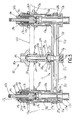
- This disposition of the first valve cartridge seat 13a and the first valve cartridge 14a is shown in relation to the sink deck 100 (indicated in chain-dashed outline) in a cross-sectional view in Fig. 5 for example.
- each of the first and second valve seats 13a, 13b is permanently connected at the factory in watertight fashion to its respective first housing 11 a and second housing 11 b.
- an annular flange 13d is disposed between the lower portion 13c and a connection portion 13e of the first valve seat 13a.
- the exterior surface of the connection portion 13e of the first valve seat 13a can be provided with a screw threaded surface.
- the screw threaded surface of the connection portion 13e of the first valve seat 13a can be selectively connected to and screwed into an internally threaded surface 11o of the lower portion of the first housing 11a.
- a compressible O-ring 13f can be disposed between the flange and the end of the lower portion of the first housing 11 a to provide a back-up or redundant seal water tight seal between the first valve cartridge seat 13a and the first housing 11a.
- the lower end of the first valve seat 13a desirably is configured for selective attachment to a conduit leading from a source of water supply.
- this selective attachment is facilitated by the provision of a screw threaded surface 13c formed in the exterior of the lower portion of the first valve seat 13a.
- a screw threaded portion can be provided on the interior surface of the lower portion of the first valve seat 13a.
- some other means of selective attachment could be configured at the lower portion of the first valve seat 13a.
- the first valve cartridge 14a desirably can include components such as a first valve stem 14c, a first sealing gasket 14d, a first threaded bolt 14e, a first inner sleeve 14f, and a first inner washer 14g. As shown in Fig.
- the exterior cylindrical surface of the free end of the spindle portion of the valve stem 14c can be provided with splines 14h that are configured to be non-rotatably received by a first valve handle 14i ( Fig. 7D ).
- the second valve cartridge 14b can be similarly configured, although the threads on the inner surface of the second inner sleeve will be pitched oppositely to the pitch on the threads of the first inner sleeve 14f so that the valves for hot and cold will turn in the conventional directions.
- a first threaded flange nut 15a desirably is provided and configured with a wide brim flange 15c on one end thereof and with an internally threaded surface 15d that is axially extending through the first threaded flange nut 15a.
- the first threaded flange nut 15a can be screwed onto the threaded exterior surface 12e on the lower section of the first threaded sleeve 12a.
- a second threaded flange nut 15b is provided and desirably configured identically to the first threaded flange nut 15a for purposes of being screwed onto the threaded exterior surface on the lower section of the second threaded sleeve 12b.
- first threaded flange nut 15a and the second threaded flange nut 15b can be replaced by two separate pieces, namely, a threaded nut and a washer.
- the washer can be configured to substitute for and function similarly as would the flange portion 15c of the first threaded flange nut 15a or the second threaded flange nut 15b.
- the presently preferred embodiment includes the first threaded flange nut 15a as a unitary structure and the second threaded flange nut 15b as a unitary structure, as they enable assembly to be performed in a slightly easier manner as only a single part must be manipulated rather than two separate parts.
- a first C-washer 16a is provided and defines internally thereof a half groove that includes an internal ledge 16c that is configured to receive thereon a circumferential section of the shoulder that is defined in the exterior surface of the valve housing.
- the shoulder 17h in the exterior surface of the valve housing is provided by the free edge 17h of the annular skirt 17c of the first extended bonnet 17a where it overlies the threaded external surface 12g of the upper section of the first threaded sleeve 12a.
- a second C-washer 16b is provided and desirably configured identically to the first C-washer 16a for purposes of engaging the shoulder of the valve housing that is provided by the free edge 17h of the annular skirt 17c of the second extended bonnet 17b where it overlies the threaded external surface 12g of the upper section of the second threaded sleeve 12b.
- the C-washers 16a, 16b automatically level the faucet 10 with respect to the upper surface of the sink deck 100.
- an elongated hollow tubular member provides a center shank 23 that defines internally thereof a central passage 23a axially through the entire length of the center shank 23.
- the central passage 23a of the center shank 23 provides a path toward the gooseneck 31 shown in Fig. 7D for fluid entering the central channel 11l of the central receptacle 11g from the first passage 11e and the second passage 11f of the main body 11.
- one end of the center shank 23 defines a relatively smooth axially extending surface 23b around the circumference of the exterior of the center shank 23.
- the smooth surface 23b of the one end of the center shank 23 defines a relatively narrow exterior diameter.
- the remaining axially extending exterior surface of the center shank 23 is defined by a threaded surface 23c having a relatively larger exterior diameter.
- a compression nut 21 is provided with an exterior portion that is configured so as to easily be engaged by a wrench or another tool for effecting rotation of the compression nut 21.
- this configuration includes a plurality of flat side facets 21a that are configured to lend themselves for grasping by a wrench.
- One end of the compression nut 21 is defined by an annular collar 21b disposed around a central opening 21c that extends axially through the compression nut 21.
- the interior surface 21d of the faceted exterior portion of the compression nut 21 defines a screw thread that is configured to be screwed on the externally threaded surface 11i of the upper projection 11h of the central receptacle 11g.
- a compression fitting 22 is disposed within the end 23b of the center shank 23 fitted into the portion of the central channel 11l defined by the upper projection 11h of the central receptacle 11g.
- the internal central opening 21c of the collar 21b of the compression nut 21 shown in Fig. 1 is configured to slideably receive therein the narrow exterior diameter end 23b of the center shank 23 that defines internally thereof the central passage 23a axially through the center shank 23.
- the compression fitting 22 is disposed between the internal cavity of the compression nut 21, the exterior surface 23b of the center shank 23 and the interior surface of the upper projection 11h.
- the compression fitting 22 Upon tightening of the compression nut 21 onto the externally threaded surface 11i of the upper projection 11h of the central receptacle 11 g, the compression fitting 22 is squeezed and compressed to provide a watertight seal of the center shank 23 to the main body 11.
- a flow control device desirably is incorporated in the center shank 23.
- a flow control device desirably includes a flow tower 27 that desirably includes a rigid flow fitting 27a configured to receive and hold therein an elongated gasket 27b.
- the exterior surface of the flow fitting 27a is received within an annular bore that is defined in the internal surface of the end 23b of the central shank 23 that is to be compression fitted to the main body 11.
- the flow fitting 27a and gasket 27b of the flow tower desirably is press-fit into the end 23b of the center shank 23 that is sealed water-tight by compression fitting 22 to the main body 11.
- the rigid flow fitting 27a of the flow tower 27 defines a central opening 27c axially through the rigid flow fitting 27a.
- the elongated gasket 27b defines axially therethrough a central channel 27d having a diameter that is less than the diameter of the central opening 27c of the flow fitting 27a but desirably is concentrically aligned therewith.
- the inlet of the central channel 27d is disposed in communication with the first passage 11e and with the second passage 11f of the main body 11 via the central channel 11l of the central receptacle 11g.
- the exterior surface of the elongated gasket 27b desirably is conically shaped and tapers as one moves away from where the elongated gasket 27b is attached to the flow fitting 27a.
- the elongated gasket 27b can provide the faucet 10 with a channel that has a diameter that is configured and sized to provide the desired maximum flow through the central passage 23a of the center shank 23.
- the elongated gasket 27b desirably is formed of rubber or other compressible material that can be squeezed and fitted into the space provided therefor by the configuration of the flow fitting 27a.
- the elongated gasket 27b desirably is formed of rubber or other compressible material that can be squeezed and fitted into the space provided therefor by the configuration of the flow fitting 27a.
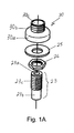
- a central threaded flange nut 24 is provided with an annular flange 24a at one end thereof.
- the central threaded flange nut 24 is provided with a threaded interior opening 24b therethrough that is configured to be screwed onto the threaded larger diameter surface 23c of center shank 23.
- the central threaded flange nut 24 is provided with an annular-shaped, recess 24c in the opposite end thereof and surrounding the interior opening 24b.
- the exterior diameter of the collar 21 b of the compression nut 21 is sufficiently smaller than the interior diameter of the annular-shaped, recess 24c of the central flange nut 24 so that the collar 21 b can be received therein and nest within the recess 24c while the threaded flange nut 24 is carried atop the compression nut 21 during the beginning of the process of installing the faucet 10 in the sink deck 100.
- the outline of the collar 21 b of the compression nut 21 is shown nesting within the annular-shaped recess of the central flange nut 24. The same arrangement would exist if the combination of the threaded nut 26 and washer 25 were resting atop the compression nut 21.
- a separate flat washer 25 and a separate threaded nut 26 can be substituted for the central threaded flange nut 24 shown in Fig. 1 .
- the threaded nut 26 is desirably provided with a recess similar to the recess 24c in the threaded flange nut 24 shown in Fig. 1 .
- the collar 21 b of the compression nut 21 would be received in and nest within the recess within the threaded nut 26 while the threaded nut 24 was carried atop the compression nut 21 during the beginning of the process of installing the faucet 10 in the sink deck 100.
- a deck flange 30 is provided with a skirt portion 30a on one end and a cylindrical portion 30b on the opposite end.
- a central conduit 30c is provided axially through the deck flange 30.
- the diameter of the central conduit 30c desirably is larger than the diameter of the central passage 23a of the center shank 23.
- the skirt 30a defines internally thereof a threaded surface 30d that is configured to engage the threaded larger diameter exterior surface 23c of the center shank 23 and can be removably screwed onto surface 23c of the center shank 23.
- the exterior surface of the cylindrical end 30b of the deck flange 30 is provided with a threaded surface that is configured to be threadedly connected to a complimentarily threaded surface of a gooseneck 31 ( Fig. 7D ).
- a bent wire hanger 40 is provided and defines a ringed opening 40a at one end thereof.
- the ringed opening 40a desirably is configured to receive therethrough the exterior surface of the central receptacle 11g of the main body 11.
- the wire hanger 40 further is configured with a pair of parallel legs 40b that extend generally at a right angle to the plane defined by the ringed opening 40a. As shown in Fig.
- each of the legs 40b is provided with a triangular recess 40c that is configured to accommodate the compression nut 21 and the annular flange 24a of the central threaded flange nut 24 and/or the combination of the threaded nut 26 and washer 25 resting atop the compression nut 21.
- a triangular recess 40c configured to accommodate the compression nut 21 and the annular flange 24a of the central threaded flange nut 24 and/or the combination of the threaded nut 26 and washer 25 resting atop the compression nut 21.
- an outwardly extending arm 40d As shown in Fig. 4 for example, each arm 40d can be rested atop the sink deck 100 when the axially extending leg of the hanger 40 is projecting through a central opening 101 defined through the sink deck 100.
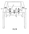
- FIG. 7A A method of installing in the deck 100 of a sink, the concealed, widespread faucet 10 in accordance with an embodiment of the present invention now will be described. It is assumed that the deck 100 of the sink has been prepared with three properly spaced and sized openings, including a central opening 101 flanked on each side by an outlying opening 102.
- the widespread faucet 10 is provided to the installer in the condition shown in Fig. 7A , which is fully assembled except for the center shank 23 and the deck flange 30, which is a component that is detachably connected to the center shank 23 but provided in the connected condition from the factory.
- the respective valve cartridges 14a, 14b and valve seats 13a, 13b are installed and connected into the main body 11 with the respective sleeves 12a, 12b and valve seats 13a, 13b permanently lock-tightened to the main body as shown in Fig. 5 for example.
- the respective extended bonnets 17a, 17b which are part of the valve housings, are connected to the respective sleeves 12a, 12b, which are connected to the respective housings 11 a, 11b of the main body 11 as shown in Fig. 5 for example.
- sealing gaskets 20a, 20b, back-up compressible O-rings 13f, packing nuts 18a, 18b and lock nuts 19a, 19b also are installed at the factory where the valves also will have been leak tested prior to being shipped to a buyer.
- the installer engages the wire hanger 40 with the central receptacle 11 g of the main body 11 resting within the ringed opening 40a of the hanger 40 as shown in Fig. 4 so that the main body can be carried by the hanger 40.
- the installer rests the central threaded flange nut 24 on the compression nut 21 with the recess 24c receiving the collar 21 b of the compression nut 21 so that the central threaded flange nut 24 is carried by the compression nut 21 in the manner shown in Fig. 4 for example.
- the installer moves the faucet 10 into the openings 101, 102 in the sink deck 100.
- Each of the valve housings is inserted through one of the flanking openings 102.
- the triangular shape of the arms 40d easily permit the arms 40d to pass through the central opening 101 in the sink deck 100.
- the triangular shape of the arms 40d of the hanger 40 ensure that the legs 40b of the hanger 40 are squeezed together as the arms 40d are pushed through the central opening 101 by the installer.
- the faucet 10 and hanger 40 are disposed as shown in Figs. 7B and 4 .
- first C-washer 16a under the shoulder formed in one of the valve housings and a second C-washer 16b under the shoulder formed in the other valve housing.
- the shoulder 17h formed at the free end of the first extended bonnet 17a of one valve housing is received in and carried by the internal ledge 16c ( Fig. 1 ) of the first C-washer 16a.
- the second C-washer 16b is inserted so as to receive in its internal ledge 16c ( Fig. 1 ) the shoulder 17h formed by the free end of the second extended bonnet 17b of the second valve housing.
- the C-washers 16a, 16b automatically level the faucet 10 with respect to the upper surface of the sink deck 100.
- each of the first and second threaded flange nuts 15a, 15b is rotated on the respective threaded exterior surfaces 12e of the lower section of each of the respective first and second threaded sleeves 12a, 12b.
- threaded flange nuts 15a, 15b are rotated until the upper surface of the rim flanges 15c are resting securely against the underside of the sink deck 100 as shown in Fig. 5 for example.
- the installer squeezes the arms 40b of the hanger 40 together and pushes the arms 40d downwardly through the central opening 101 of the sink deck 100 until the hanger 40 disengages from the sink deck 100 and from the central receptacle 11 g of the main body 11.
- This condition is shown in Fig. 7C as the hanger 40 is falling in the direction of the arrow disposed just above hanger 40 in Fig. 7C .
- the installer can insert from above the deck 100, the center shank 23 with the deck flange 30, which has been tightened and sealed at the factory onto the free end of the threaded exterior surface 23c of the center shank 23. Because this can be done under factory conditions, the seal is more reliable and installation time is reduced.
- the installer inserts the center shank 23 through the central opening 101 until the free end of the center shank 23 with the smooth exterior surface 23b is inserted into the upper projection 11h of the central receptacle 11g.
- the installer then secures the center shank 23 to the main body 11 by tightening the compression nut 21 onto the upper projection 11h of the central receptacle 11g of the main body 11. As shown in Fig.
- the compression fitted center shank 23 allows for tolerance stacking caused by variations in material manufacturing and sink levelness.
- the compression fitted center shank 23 accomplishes this advantage automatically without any necessary adjustments needed from the installer.
- the installer will need to tighten with a wrench or similar tool, in the following order, the two threaded flange nuts 15a, 15b, followed by the central threaded flange nut 24 and then the compression nut 21.
- the two threaded flange nuts 15a, 15b and the central threaded flange nut 24 are the three nuts 15a, 15b and 24 disposed against the underside of the sink deck 100.
- the one compression nut 21 is also disposed beneath the sink deck 100 but only connects the center shank 23 to the main body 11.
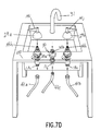
- the wide spread faucet 10 is installed to the sink deck 100 as shown in Figs. 2 and 7D for example.
- the main body 11 is concealed beneath the sink deck 100, which is secured to one of the valve housings by being held between a brim flange 15c and the first C-washer 16a.
- the sink deck 100 is secured to the other one of the valve housings by being held between a brim flange 15c and the second C-washer 16b.
- the sink deck 100 is secured to the center shank 23 by being held between an annular flange 24a (or washer 25 and nut 26) and the skirt portion 30a of the deck flange 30.
- the installer can connect the aesthetically pleasing components, which include escutcheons 29a, 29b to cover the portions of the valve housings that are exposed above the upper surface of the sink deck 100.
- the installer can attach each handle 14i, 14j to the splines 14h at the free end of each valve stem of each valve cartridge.
- One end of a gooseneck 31 can be connected to the cylindrical end 30b of the deck flange 30.
- the installer can connect the appropriate water supply conduit 41 a, 41 b to one of the screw threaded surfaces 13c at the lower end of each valve seat 13a, 13b.
- the installer can connect a third supply conduit 41 c to the central receptacle 11g.
- Such a third supply conduit 41 c optionally can be used for a side spray as one would find in a typical kitchen sink or to supply a pedal valve as one would find in a doctor's scrub room to enable the doctor to operate the sink's water supply using a foot instead of the doctor's hands.
- the time to install this widespread faucet 10 is about 3 minutes or less for the plumber, and can be installed by less skilled labor such as the plumber's helper in the same amount of time.
- the widespread faucet 10 is pre-assembled at the factory, self leveling and has fewer nuts to tighten than conventional sinks.
- the invention also provides a method of installing a concealed, wide spread faucet in a sink deck defining three openings, the faucet including a main body, the main body defining a first housing connected to a first valve housing and containing a first valve cartridge and first valve seat, the main body defining a second housing connected to a second valve housing and containing a second valve cartridge and second valve seat, the main body defining a receptacle for receiving a center shank, the receptacle being disposed between the first and second housings, the main body defining a hollow first branch disposed between the first housing and the receptacle, the main body defining a hollow second branch disposed between the second housing and the receptacle, wherein the main body defines a unitary structure, the method comprising:
- the method may further comprise securing each valve housing to the sink deck.
- the method may further comprise inserting the center shank through a third one of the openings in the sink deck from above the sink deck and connecting the center shank to the sink deck with one end of the center shank projecting above the sink deck.
- the method may further comprise connecting the other end of the center shank to the main body.
- the method may further provide that the hanger projects through a third one of the sink deck openings with one portion of the hanger engaging the main body and another portion of the hanger engaging the sink deck.
- the method may further comprise wherein before inserting the center shank, the hanger is disengaged from the main body and from the sink deck.
- the method may further comprise that before connecting one end of the center shank to the sink deck, a center flange nut is carried by a compression nut while one end of the center shank is passed through a third one of the sink deck openings and into the main body after passing through the both the compression nut and the center flange nut.
Landscapes
- Health & Medical Sciences (AREA)
- Life Sciences & Earth Sciences (AREA)
- Engineering & Computer Science (AREA)
- Hydrology & Water Resources (AREA)
- Public Health (AREA)
- Water Supply & Treatment (AREA)
- Valve Housings (AREA)
- Domestic Plumbing Installations (AREA)
Applications Claiming Priority (1)
| Application Number | Priority Date | Filing Date | Title |
|---|---|---|---|
| US12/052,249 US7472434B1 (en) | 2008-03-20 | 2008-03-20 | Concealed widespread faucet and method of installing same |
Publications (2)
| Publication Number | Publication Date |
|---|---|
| EP2103748A2 true EP2103748A2 (fr) | 2009-09-23 |
| EP2103748A3 EP2103748A3 (fr) | 2015-03-04 |
Family
ID=40174848
Family Applications (1)
| Application Number | Title | Priority Date | Filing Date |
|---|---|---|---|
| EP20080006592 Withdrawn EP2103748A3 (fr) | 2008-03-20 | 2008-03-31 | Robinet à large dispersion, caché, et son procédé d'installation |
Country Status (3)
| Country | Link |
|---|---|
| US (1) | US7472434B1 (fr) |
| EP (1) | EP2103748A3 (fr) |
| CN (1) | CN101539216B (fr) |
Families Citing this family (14)
| Publication number | Priority date | Publication date | Assignee | Title |
|---|---|---|---|---|
| US7661155B2 (en) * | 2006-10-26 | 2010-02-16 | Tsai-Chen Yang | Lateral driving faucet water outlet seat |
| US20100127202A1 (en) * | 2008-11-26 | 2010-05-27 | Moen Incorporated | Valve body |
| CA2796796C (fr) * | 2010-05-21 | 2015-03-24 | Masco Corporation Of Indiana | Ancrage de montage de robinet |
| US20120103438A1 (en) * | 2010-11-01 | 2012-05-03 | Jui-Feng Ko | One-handle Type Faucet having a double anti-reverse function to prevent waste materials from flowing backward into the faucet when disaster happens |
| ES2940096T3 (es) | 2011-07-29 | 2023-05-03 | Hayward Ind Inc | Cartuchos de células reemplazables para cloradores |
| WO2013019748A1 (fr) * | 2011-07-29 | 2013-02-07 | Hayward Industries, Inc. | Systèmes et procédés pour chlorateurs pouvant être installés par un utilisateur |
| EP2736848A4 (fr) | 2011-07-29 | 2016-03-16 | Hayward Ind Inc | Systèmes et procédés de commande de chloromètres |
| GB201516055D0 (en) * | 2015-09-10 | 2015-10-28 | Fresh Water Filter Company The Ltd | Water tap body |
| CN106090294B (zh) * | 2016-08-22 | 2018-04-24 | 开平市沃特卫浴有限公司 | 一种阀芯座组件 |
| TR201619436A3 (tr) * | 2016-12-23 | 2018-10-22 | Eczacibasi Yapi Gerecleri Sanayi Ve Ticaret Anonim Sirketi | Bi̇r siva alti bağlanti si̇stemi̇ |
| EP4679084A3 (fr) | 2017-03-21 | 2026-03-25 | Hayward Industries, Inc. | Systèmes et procédés de désinfection d'eau de piscine et de spa |
| US12065811B2 (en) * | 2018-08-23 | 2024-08-20 | Danco, Inc. | Systems and methods for coupling of a tub spout |
| US20240183459A1 (en) * | 2022-12-01 | 2024-06-06 | As America, Inc. | Faucet Rough-In Assembly |
| US20250277536A1 (en) * | 2024-02-29 | 2025-09-04 | Evertek Industries Inc. | Water release apparatus |
Citations (1)
| Publication number | Priority date | Publication date | Assignee | Title |
|---|---|---|---|---|
| US7306005B2 (en) | 2005-12-14 | 2007-12-11 | T&S Brass And Bronze Works, Inc. | Valve and valve cartridge |
Family Cites Families (10)
| Publication number | Priority date | Publication date | Assignee | Title |
|---|---|---|---|---|
| US3998240A (en) * | 1975-06-13 | 1976-12-21 | Liautaud James P | Injection-molded faucet assembly |
| GB1515257A (en) * | 1977-03-10 | 1978-06-21 | Barking Brassware | Water fittings |
| US4502165A (en) * | 1983-05-11 | 1985-03-05 | Price Pfister, Inc. | Washer and nut combination for locking plumbing fixtures to a sink deck or the like |
| US5232008A (en) * | 1992-12-14 | 1993-08-03 | Moen Incorporated | Two handle faucet and mounting structure therefor |
| US5865211A (en) * | 1996-04-30 | 1999-02-02 | Masco Corporation Of Indiana | Faucet installation aid |
| US6220279B1 (en) * | 1997-10-31 | 2001-04-24 | Emhart Inc. | Faucet assembly |
| US6220278B1 (en) * | 2000-01-13 | 2001-04-24 | Kohler Co. | Top mounting faucet assembly |
| US6273138B1 (en) * | 2000-05-12 | 2001-08-14 | James L. Yoney | Adjustable faucet assembly |
| CA2343294C (fr) * | 2001-04-05 | 2005-01-25 | Chung Cheng Faucet Co., Ltd. | Corps de chambre de robinet |
| US7207075B2 (en) * | 2001-11-20 | 2007-04-24 | Speakman Company | Interchangeable gooseneck faucet |
-
2008
- 2008-03-20 US US12/052,249 patent/US7472434B1/en active Active
- 2008-03-31 EP EP20080006592 patent/EP2103748A3/fr not_active Withdrawn
- 2008-06-30 CN CN200810137605XA patent/CN101539216B/zh active Active
Patent Citations (1)
| Publication number | Priority date | Publication date | Assignee | Title |
|---|---|---|---|---|
| US7306005B2 (en) | 2005-12-14 | 2007-12-11 | T&S Brass And Bronze Works, Inc. | Valve and valve cartridge |
Also Published As
| Publication number | Publication date |
|---|---|
| CN101539216B (zh) | 2013-09-11 |
| CN101539216A (zh) | 2009-09-23 |
| EP2103748A3 (fr) | 2015-03-04 |
| US7472434B1 (en) | 2009-01-06 |
Similar Documents
| Publication | Publication Date | Title |
|---|---|---|
| US7472434B1 (en) | Concealed widespread faucet and method of installing same | |
| CA2475465C (fr) | Robinet et ensemble d'ecoulement combines | |
| US7055545B2 (en) | Modular center set faucet and valve body | |
| CN100380039C (zh) | 带有安装简便预清洗单元机构的龙头组件 | |
| US7658202B2 (en) | Low-profile valve assembly | |
| US6360770B1 (en) | Modular lavatory faucet spout mounting | |
| KR100192152B1 (ko) | 수도꼭지 조립체 및 그 설치 방법 | |
| US20240376699A1 (en) | Bath Waste And Overflow Systems And Methods Of Use | |
| US11702829B2 (en) | Kits for reducing inventory of sink drain assemblies | |
| US20130199623A1 (en) | Tap mounting | |
| US7409968B2 (en) | Faucet with a water outlet controlled by a central pull stick | |
| GB2454506A (en) | Mounting means for tap | |
| KR100478083B1 (ko) | 보조공급수 연결용 튜브가 접속되는 수도꼭지 연결구 | |
| JP4898554B2 (ja) | 立形水栓への分岐給水用アダプターの取付構造 | |
| CA2886549C (fr) | Methode et equipement associe permettant d'installer et de mettre a l'epreuve une installation de plomberie | |
| JPS6020696Y2 (ja) | 立形水栓の固定装置 | |
| JPS6019174Y2 (ja) | 立形水栓の固定装置 | |
| AU2003270936A1 (en) | Tapware Mounting System | |
| IES84073Y1 (en) | Connection for water meter | |
| GB2410975A (en) | Water meter connection | |
| IE20050057U1 (en) | Connection for water meter | |
| HK1115422A (en) | Faucet assembly with integral water supply shut-off valve |
Legal Events
| Date | Code | Title | Description |
|---|---|---|---|
| PUAI | Public reference made under article 153(3) epc to a published international application that has entered the european phase |
Free format text: ORIGINAL CODE: 0009012 |
|
| AK | Designated contracting states |
Kind code of ref document: A2 Designated state(s): AT BE BG CH CY CZ DE DK EE ES FI FR GB GR HR HU IE IS IT LI LT LU LV MC MT NL NO PL PT RO SE SI SK TR |
|
| AX | Request for extension of the european patent |
Extension state: AL BA MK RS |
|
| PUAL | Search report despatched |
Free format text: ORIGINAL CODE: 0009013 |
|
| AK | Designated contracting states |
Kind code of ref document: A3 Designated state(s): AT BE BG CH CY CZ DE DK EE ES FI FR GB GR HR HU IE IS IT LI LT LU LV MC MT NL NO PL PT RO SE SI SK TR |
|
| AX | Request for extension of the european patent |
Extension state: AL BA MK RS |
|
| RIC1 | Information provided on ipc code assigned before grant |
Ipc: E03C 1/04 20060101AFI20150128BHEP |
|
| 17P | Request for examination filed |
Effective date: 20150505 |
|
| AKX | Designation fees paid |
Designated state(s): GB |
|
| AXX | Extension fees paid |
Extension state: AL Extension state: RS Extension state: MK Extension state: BA |
|
| REG | Reference to a national code |
Ref country code: DE Ref legal event code: R108 |
|
| STAA | Information on the status of an ep patent application or granted ep patent |
Free format text: STATUS: THE APPLICATION HAS BEEN WITHDRAWN |
|
| 18W | Application withdrawn |
Effective date: 20171019 |