EP2103749A2 - Auslauf, insbesondere für Waschbecken und dergleichen, mit Vorrichtung zur automatischen Aktivierung eines Ventilgehäuses - Google Patents
Auslauf, insbesondere für Waschbecken und dergleichen, mit Vorrichtung zur automatischen Aktivierung eines Ventilgehäuses Download PDFInfo
- Publication number
- EP2103749A2 EP2103749A2 EP09151907A EP09151907A EP2103749A2 EP 2103749 A2 EP2103749 A2 EP 2103749A2 EP 09151907 A EP09151907 A EP 09151907A EP 09151907 A EP09151907 A EP 09151907A EP 2103749 A2 EP2103749 A2 EP 2103749A2
- Authority
- EP
- European Patent Office
- Prior art keywords
- valve body
- spout
- tubular element
- tubular
- washbasin
- Prior art date
- Legal status (The legal status is an assumption and is not a legal conclusion. Google has not performed a legal analysis and makes no representation as to the accuracy of the status listed.)
- Withdrawn
Links
- 230000004913 activation Effects 0.000 title claims abstract description 16
- 238000005276 aerator Methods 0.000 claims abstract description 11
- 239000003990 capacitor Substances 0.000 claims description 4
- 239000000919 ceramic Substances 0.000 claims description 3
- 238000009413 insulation Methods 0.000 claims description 2
- 238000001994 activation Methods 0.000 description 13
- 238000010292 electrical insulation Methods 0.000 description 2
- 230000000670 limiting effect Effects 0.000 description 2
- 239000000463 material Substances 0.000 description 2
- XLYOFNOQVPJJNP-UHFFFAOYSA-N water Substances O XLYOFNOQVPJJNP-UHFFFAOYSA-N 0.000 description 2
- 230000003213 activating effect Effects 0.000 description 1
- 238000004140 cleaning Methods 0.000 description 1
- 230000008878 coupling Effects 0.000 description 1
- 238000010168 coupling process Methods 0.000 description 1
- 238000005859 coupling reaction Methods 0.000 description 1
- 238000001514 detection method Methods 0.000 description 1
- 230000001939 inductive effect Effects 0.000 description 1
- 238000009434 installation Methods 0.000 description 1
- 230000004048 modification Effects 0.000 description 1
- 238000012986 modification Methods 0.000 description 1
Images
Classifications
-
- E—FIXED CONSTRUCTIONS
- E03—WATER SUPPLY; SEWERAGE
- E03C—DOMESTIC PLUMBING INSTALLATIONS FOR FRESH WATER OR WASTE WATER; SINKS
- E03C1/00—Domestic plumbing installations for fresh water or waste water; Sinks
- E03C1/02—Plumbing installations for fresh water
- E03C1/04—Water-basin installations specially adapted to wash-basins or baths
- E03C1/0404—Constructional or functional features of the spout
-
- E—FIXED CONSTRUCTIONS
- E03—WATER SUPPLY; SEWERAGE
- E03C—DOMESTIC PLUMBING INSTALLATIONS FOR FRESH WATER OR WASTE WATER; SINKS
- E03C1/00—Domestic plumbing installations for fresh water or waste water; Sinks
- E03C1/02—Plumbing installations for fresh water
- E03C1/05—Arrangements of devices on wash-basins, baths, sinks, or the like for remote control of taps
- E03C1/055—Electrical control devices, e.g. with push buttons, control panels or the like
Definitions
- the present invention relates to a spout, particularly for washbasins and the like, with device for automatic activation of a valve body.
- the invention relates to a spout that comprises a time-controlled valve body with automatic activation, combined with a battery-powered ceramic or thermostatic cartridge.
- motion detection devices which comprise a photocell or a proximity sensor that is installed proximate to the spout of the washbasin and is adapted to detect the presence of the user in order to open and/or close the valve body of the faucet.
- closure of the valve body is linked to a timer, which is activated simultaneously with the opening of the valve body and, once the preset time has elapsed, closes the valve body automatically.
- Another type of automatic activation devices is constituted by contact devices.
- This last type of device is characterized by the presence of capacitive or inductive contact sensor means, which are associated with the spout of the washbasin to operate the valve body of the faucet when the user touches the spout of the washbasin.
- the spout of the washbasin in fact becomes a totally sensitive element, which is connected to a control unit that measures the variation in capacitance or inductance that is associated with an electric circuit connected to the spout of the washbasin.
- the aim of the present invention is to eliminate the drawback noted above by providing a spout, particularly for washbasins and the like, with a device for the automatic activation of a valve body that allows to actuate the valve body only when this is actually required, without possibility of error.
- an object of the present invention is to provide a spout for washbasins that is easy to install and uses easily available components.
- a spout particularly for washbasins and the like, with a device for the automatic activation of a valve body, comprising a tubular body that can be associated with a valve body of a washbasin at a first end thereof and is associated, at a second end thereof, with an aerator, which can be sealingly connected to said valve body by means of a pipe that lies inside said tubular body, characterized in that said tubular body comprises a first tubular element and a second tubular element, which are associated to each other, without mutual contact, by means of an insulating element, said second tubular element being associated with said aerator and being associated with contact sensor means that are connected to means for actuating said valve body, forming a contact sensitive region arranged at the end of the spout of the washbasin.
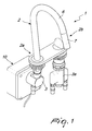
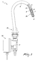
- the spout particularly for washbasins and the like, with device for automatic activation of a valve body, generally designated by the reference numeral 1, comprises a tubular body 2, which substantially has a cylindrical cross-section and can be associated with a valve body 3 of a washbasin at a first end thereof 2a and is associated, at a second end thereof 2b, with an aerator 4, according to a system that is per se known and therefore is not described.
- the spout is further associated with a battery-powered thermostatic or ceramic cartridge 3a.
- the aerator 4 can be sealingly connected to the valve body by means of a flexible hose or pipe 5 that lies inside the tubular body 2.
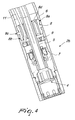
- the tubular body 2 comprises a first tubular element 6 and a second tubular element 7, which are associated to each other without mutual contact by means of an insulating element, which consists of a bush 8 that is sealingly inserted with a first portion thereof 8a in the first tubular element 6 and with a second portion thereof 8b in the second tubular element 7.
- first tubular element 6 and the second tubular element 7 Electrical insulation between the first tubular element 6 and the second tubular element 7 is achieved by way of a radial expansion 8c, which is formed on the bush 8 and is arranged between the first portion 8a and the second portion 8b of the bush.
- the materials of the bush 8, of the first tubular element 6 and of the second tubular element 7 are selected appropriately in order to provide an electrical insulation between the first tubular element 6 and the second tubular element 7.
- the second tubular element 7 is associated with the aerator 4 and is associated with contact sensor means of the capacitive type, which comprise at least a contact element 9 that acts as a first electrode of the capacitor.
- the second electrode of the capacitor is the user proper.
- the contact element 9 is a ring that is screwed inside the second tubular element 7, since the latter has a circular cross-section.
- connection between the first and second tubular elements 6 and 7 and the bush 8 is also provided by way of a threaded coupling with a male thread on the bush 8, on both portions 8a and 8b, and female threads on the first and second tubular elements 6 and 7.
- the contact element 9 is connected to means for actuating the valve body 3, which comprise at least one control unit 10, which can be arranged inside the washbasin in order to manage and control the valve body 3 by means of at least one wire 11.
- the bush 8 comprises a through hole 8d along its axis.
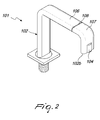
- the spout in a second possible embodiment, shown in Figure 2 , can comprise a tubular body 102 that has substantially a rectangular cross-section with rounded edges.
- the tubular body 102 comprises a first and second tubular elements 106 and 107, which are associated to each other without mutual contact by means of an insulation element, which consists of a bush 108 that is sealingly inserted in the first tubular element 106 and in the second tubular element 107.
- the aerator 104 in any case maintains a cylindrical cross-section and is associated with the end 102b of the tubular body 102.
- the internal components, the control unit and the valve body can remain substantially unchanged.
- the contact element 9 acts as a first electrode of a capacitor, the second electrode of which is provided by the body of the user.
- the control unit 10 performs the function of detecting the difference in capacitance associated with the first electrode, provided by the contact element 9, and of activating the valve body 3 for the outflow of the water from the spout.
- Another advantage of the spout according to the present invention consists in that it is provided by means of components that are easily available, thereby entailing a low cost thereof and an easy installation.
- the materials used may be any according to requirements and to the state of the art.
Landscapes
- Health & Medical Sciences (AREA)
- Life Sciences & Earth Sciences (AREA)
- Engineering & Computer Science (AREA)
- Hydrology & Water Resources (AREA)
- Public Health (AREA)
- Water Supply & Treatment (AREA)
- Domestic Plumbing Installations (AREA)
- Lift Valve (AREA)
- Detergent Compositions (AREA)
Applications Claiming Priority (1)
| Application Number | Priority Date | Filing Date | Title |
|---|---|---|---|
| ITMI20080473 ITMI20080473A1 (it) | 2008-03-19 | 2008-03-19 | Canna, particolarmente per lavabi e simili, con dispositivo di attivazione automatica di un corpo valvola. |
Publications (2)
| Publication Number | Publication Date |
|---|---|
| EP2103749A2 true EP2103749A2 (de) | 2009-09-23 |
| EP2103749A3 EP2103749A3 (de) | 2013-10-02 |
Family
ID=40292931
Family Applications (1)
| Application Number | Title | Priority Date | Filing Date |
|---|---|---|---|
| EP09151907.4A Withdrawn EP2103749A3 (de) | 2008-03-19 | 2009-02-03 | Auslauf, insbesondere für Waschbecken und dergleichen, mit Vorrichtung zur automatischen Aktivierung eines Ventilgehäuses |
Country Status (2)
| Country | Link |
|---|---|
| EP (1) | EP2103749A3 (de) |
| IT (1) | ITMI20080473A1 (de) |
Cited By (6)
| Publication number | Priority date | Publication date | Assignee | Title |
|---|---|---|---|---|
| EP2775046A1 (de) * | 2013-03-07 | 2014-09-10 | Grohe AG | Sanitärarmatur mit elektrischem Sensor |
| USD713508S1 (en) | 2014-02-21 | 2014-09-16 | Price Pfister, Inc. | Faucet |
| USD713510S1 (en) | 2014-02-21 | 2014-09-16 | Price Pfister, Inc. | Spout body |
| USD723662S1 (en) | 2014-04-02 | 2015-03-03 | Price Pfister, Inc. | Faucet |
| EP2669558A4 (de) * | 2011-01-30 | 2017-05-31 | Guangzhou Seagull Kitchen And Bath Products Co., Ltd. | Auf den menschlichen körper reagierende berührungsgesteuerte wasserauslassvorrichtung und steuerverfahren dafür |
| EP3477008A1 (de) * | 2017-10-25 | 2019-05-01 | Grohe AG | Sanitärarmatur mit einem sensor und verfahren zum steuern und zur herstellung einer sanitärarmatur mit einem sensor |
Family Cites Families (3)
| Publication number | Priority date | Publication date | Assignee | Title |
|---|---|---|---|---|
| JP4999273B2 (ja) * | 2002-12-04 | 2012-08-15 | スローン バルブ カンパニー | 自動蛇口及び水洗装置のためのパッシブセンサ |
| DE102005028600B4 (de) * | 2005-06-21 | 2009-02-12 | Hansa Metallwerke Ag | Sanitäre Wasserauslaufarmatur mit wenigstens einer Betätigungseinrichtung zum Ändern der Wassertemperatur und/oder des Wasservolumenstroms |
| US20070069169A1 (en) * | 2005-09-27 | 2007-03-29 | Hui-Huang Lin | Touch-flow water supply apparatus |
-
2008
- 2008-03-19 IT ITMI20080473 patent/ITMI20080473A1/it unknown
-
2009
- 2009-02-03 EP EP09151907.4A patent/EP2103749A3/de not_active Withdrawn
Cited By (8)
| Publication number | Priority date | Publication date | Assignee | Title |
|---|---|---|---|---|
| EP2669558A4 (de) * | 2011-01-30 | 2017-05-31 | Guangzhou Seagull Kitchen And Bath Products Co., Ltd. | Auf den menschlichen körper reagierende berührungsgesteuerte wasserauslassvorrichtung und steuerverfahren dafür |
| EP2775046A1 (de) * | 2013-03-07 | 2014-09-10 | Grohe AG | Sanitärarmatur mit elektrischem Sensor |
| CN104033640A (zh) * | 2013-03-07 | 2014-09-10 | 高仪股份公司 | 配有电传感器的卫生配件 |
| CN104033640B (zh) * | 2013-03-07 | 2018-03-23 | 高仪股份公司 | 配有电传感器的卫生配件 |
| USD713508S1 (en) | 2014-02-21 | 2014-09-16 | Price Pfister, Inc. | Faucet |
| USD713510S1 (en) | 2014-02-21 | 2014-09-16 | Price Pfister, Inc. | Spout body |
| USD723662S1 (en) | 2014-04-02 | 2015-03-03 | Price Pfister, Inc. | Faucet |
| EP3477008A1 (de) * | 2017-10-25 | 2019-05-01 | Grohe AG | Sanitärarmatur mit einem sensor und verfahren zum steuern und zur herstellung einer sanitärarmatur mit einem sensor |
Also Published As
| Publication number | Publication date |
|---|---|
| EP2103749A3 (de) | 2013-10-02 |
| ITMI20080473A1 (it) | 2009-09-20 |
Similar Documents
| Publication | Publication Date | Title |
|---|---|---|
| EP2103749A2 (de) | Auslauf, insbesondere für Waschbecken und dergleichen, mit Vorrichtung zur automatischen Aktivierung eines Ventilgehäuses | |
| US6543479B2 (en) | Water monitoring system | |
| US8424568B2 (en) | Control device for plumbing appliances | |
| CN103629412B (zh) | 用于将传感器定位和保持在龙头喷口中的系统和方法 | |
| CN101563561B (zh) | 多模式免手动自动龙头 | |
| US8973612B2 (en) | Capacitive sensing electronic faucet including differential measurements | |
| US9284724B2 (en) | Universal capacitance-type touch inductive switch assembly for faucet | |
| EP1250495B1 (de) | Überlaufsystem | |
| US20090293192A1 (en) | Apparatus and system for automatic activation and de-activation of water flow | |
| JP2008531880A5 (de) | ||
| JP2008531880A (ja) | 自動近接蛇口 | |
| CN105817070A (zh) | 远程控制的水龙头过滤器系统 | |
| EP2995728B1 (de) | Berührungsfreie automatische wasserversorgungsvorrichtung und verfahren | |
| EP1850202A1 (de) | Intelligentes Verwaltungssystem zum Einsparen von Wasser | |
| US5209254A (en) | Water and sewerage system for construction, and protection for the same | |
| EP1819885B1 (de) | Pumpabwasser | |
| KR101666380B1 (ko) | 싱크용 터치 수전장치 | |
| US20170268209A1 (en) | Passive fluid regulation system | |
| WO2014163930A1 (en) | Apparatus and method for reducing cross-talk between capacitive sensors | |
| KR102332686B1 (ko) | 지능형 전자동 수세식 변기 구조 | |
| EP3455420B1 (de) | Wasserversorgungssystem | |
| KR101666382B1 (ko) | 싱크용 터치 수전장치 | |
| KR200402556Y1 (ko) | 터치센서를 이용한 절수장치 | |
| JP7614588B2 (ja) | 排水栓装置 | |
| KR101889022B1 (ko) | 소변기에 설치되는 밸브유닛과 스프레더의 결합구조 |
Legal Events
| Date | Code | Title | Description |
|---|---|---|---|
| PUAI | Public reference made under article 153(3) epc to a published international application that has entered the european phase |
Free format text: ORIGINAL CODE: 0009012 |
|
| AK | Designated contracting states |
Kind code of ref document: A2 Designated state(s): AT BE BG CH CY CZ DE DK EE ES FI FR GB GR HR HU IE IS IT LI LT LU LV MC MK MT NL NO PL PT RO SE SI SK TR |
|
| AX | Request for extension of the european patent |
Extension state: AL BA RS |
|
| RAP1 | Party data changed (applicant data changed or rights of an application transferred) |
Owner name: NUOVA OSMO S.R.L. |
|
| PUAL | Search report despatched |
Free format text: ORIGINAL CODE: 0009013 |
|
| AK | Designated contracting states |
Kind code of ref document: A3 Designated state(s): AT BE BG CH CY CZ DE DK EE ES FI FR GB GR HR HU IE IS IT LI LT LU LV MC MK MT NL NO PL PT RO SE SI SK TR |
|
| AX | Request for extension of the european patent |
Extension state: AL BA RS |
|
| RIC1 | Information provided on ipc code assigned before grant |
Ipc: E03C 1/05 20060101AFI20130828BHEP Ipc: E03C 1/04 20060101ALI20130828BHEP |
|
| AKY | No designation fees paid | ||
| REG | Reference to a national code |
Ref country code: DE Ref legal event code: R108 |
|
| REG | Reference to a national code |
Ref country code: DE Ref legal event code: R108 Effective date: 20140611 |
|
| STAA | Information on the status of an ep patent application or granted ep patent |
Free format text: STATUS: THE APPLICATION IS DEEMED TO BE WITHDRAWN |
|
| 18D | Application deemed to be withdrawn |
Effective date: 20140403 |