EP2103759A1 - Elément de coffrage - Google Patents
Elément de coffrage Download PDFInfo
- Publication number
- EP2103759A1 EP2103759A1 EP09003902A EP09003902A EP2103759A1 EP 2103759 A1 EP2103759 A1 EP 2103759A1 EP 09003902 A EP09003902 A EP 09003902A EP 09003902 A EP09003902 A EP 09003902A EP 2103759 A1 EP2103759 A1 EP 2103759A1
- Authority
- EP
- European Patent Office
- Prior art keywords
- layer
- plates
- element according
- layers
- shuttering element
- Prior art date
- Legal status (The legal status is an assumption and is not a legal conclusion. Google has not performed a legal analysis and makes no representation as to the accuracy of the status listed.)
- Withdrawn
Links
- 239000011087 paperboard Substances 0.000 claims abstract description 7
- 239000011111 cardboard Substances 0.000 claims abstract description 6
- 238000009415 formwork Methods 0.000 claims description 29
- 238000009416 shuttering Methods 0.000 claims description 14
- 241000264877 Hippospongia communis Species 0.000 claims description 13
- 239000011888 foil Substances 0.000 abstract description 2
- 239000000463 material Substances 0.000 description 11
- 229920006300 shrink film Polymers 0.000 description 5
- 239000011810 insulating material Substances 0.000 description 3
- 238000009413 insulation Methods 0.000 description 3
- 239000011490 mineral wool Substances 0.000 description 3
- 239000000123 paper Substances 0.000 description 3
- 238000010521 absorption reaction Methods 0.000 description 2
- 230000003993 interaction Effects 0.000 description 2
- 239000003562 lightweight material Substances 0.000 description 2
- 230000000087 stabilizing effect Effects 0.000 description 2
- 239000004698 Polyethylene Substances 0.000 description 1
- 239000004793 Polystyrene Substances 0.000 description 1
- 229910000831 Steel Inorganic materials 0.000 description 1
- 230000001419 dependent effect Effects 0.000 description 1
- 229920006248 expandable polystyrene Polymers 0.000 description 1
- 239000002657 fibrous material Substances 0.000 description 1
- 239000006260 foam Substances 0.000 description 1
- 239000008187 granular material Substances 0.000 description 1
- 230000004048 modification Effects 0.000 description 1
- 238000012986 modification Methods 0.000 description 1
- 239000004033 plastic Substances 0.000 description 1
- 229920003023 plastic Polymers 0.000 description 1
- -1 polyethylene Polymers 0.000 description 1
- 229920000573 polyethylene Polymers 0.000 description 1
- 229920002223 polystyrene Polymers 0.000 description 1
- 239000010959 steel Substances 0.000 description 1
- 239000012720 thermal barrier coating Substances 0.000 description 1
- XLYOFNOQVPJJNP-UHFFFAOYSA-N water Substances O XLYOFNOQVPJJNP-UHFFFAOYSA-N 0.000 description 1
- 238000009736 wetting Methods 0.000 description 1
Images

Classifications
-
- E—FIXED CONSTRUCTIONS
- E04—BUILDING
- E04G—SCAFFOLDING; FORMS; SHUTTERING; BUILDING IMPLEMENTS OR AIDS, OR THEIR USE; HANDLING BUILDING MATERIALS ON THE SITE; REPAIRING, BREAKING-UP OR OTHER WORK ON EXISTING BUILDINGS
- E04G9/00—Forming or shuttering elements for general use
- E04G9/02—Forming boards or similar elements
- E04G9/021—Forming boards or similar elements the form surface being of cardboard
-
- E—FIXED CONSTRUCTIONS
- E04—BUILDING
- E04G—SCAFFOLDING; FORMS; SHUTTERING; BUILDING IMPLEMENTS OR AIDS, OR THEIR USE; HANDLING BUILDING MATERIALS ON THE SITE; REPAIRING, BREAKING-UP OR OTHER WORK ON EXISTING BUILDINGS
- E04G9/00—Forming or shuttering elements for general use
- E04G9/08—Forming boards or similar elements, which are collapsible, foldable, or able to be rolled up
- E04G9/086—Forming boards or similar elements, which are collapsible, foldable, or able to be rolled up which are specially adapted to be degradable in time, e.g. by moisture or water
-
- E—FIXED CONSTRUCTIONS
- E04—BUILDING
- E04G—SCAFFOLDING; FORMS; SHUTTERING; BUILDING IMPLEMENTS OR AIDS, OR THEIR USE; HANDLING BUILDING MATERIALS ON THE SITE; REPAIRING, BREAKING-UP OR OTHER WORK ON EXISTING BUILDINGS
- E04G9/00—Forming or shuttering elements for general use
- E04G9/10—Forming or shuttering elements for general use with additional peculiarities such as surface shaping, insulating or heating, permeability to water or air
Definitions
- the invention relates to a formwork element with a layer structure.
- a layer structure is understood to mean an element which has several layers.
- shuttering elements known, for example DE 38 15 870 C1 in which a steel mesh mat is covered by a foil.
- the film is a stable shrink film, for example made of polyethylene, with which the latticework of Baustahlmatte is shrunk, so that the grid openings are each closed by two layers of film and thus one obtains a flat, concrete impermeable formwork element.
- the object of the invention is to provide a novel, lightweight formwork element.
- the layer structure comprises two plates, wherein the plates each have at least one layer having a plurality of layers, and wherein a wavy layer of a layer of a plate and a wavy layer of a layer of other plate are wavy in different directions.
- a wave of a wave-like layer of a layer of the one plate extends transversely to a shaft of a wave-like layer of a layer of the other plate.
- the formwork element according to the invention is used for permanent formwork, for example foundation formworks, then it may be advantageous if the material of the formwork element rots gradually after moisture absorption.
- the layer structure has a structure arranged between the plates, preferably a honeycomb structure, wherein walls which form the structure extend transversely to the plates.
- a honeycomb structure is understood to mean an element which has a large number of honeycombs.
- the walls of the structure are glued to the plates. Due to the stabilizing interaction of the structure and the plates, a high stability of the formwork element can be achieved at the same time as low weight using suitable, thin, lightweight materials. It also comes into consideration materials for the plates and the structure that could not previously be used for lost formwork. In particular, low density materials such as paper or paperboard can be used.
- said walls are made of paper or cardboard.
- said walls are formed by strips each defining a plurality of honeycombs together with adjacent strips.
- the strips are kinked or bent, such as zigzag or wavy. They are preferably glued together.
- the plates each have at least one layer with a plurality of layers, of which at least one layer is wavy.
- the layers of paper or cardboard Preferably, the layers of paper or cardboard.
- a wave-shaped layer results in high material stability at low material density.
- the plates each have at least two such layers whose undulating layers are corrugated in different directions.
- the wave of a wave-like layer of a layer can extend transversely to the wave of a wave-like layer of another, in particular adjacent layer.
- the plates each have three such layers, each with a wave-like layer.
- the plates can also be constructed differently, and the described characteristics of the plates can be present in only one of the two plates.
- the layer structure is covered by a film.
- the layer structure is protected against wetting.
- the film is perforated. Due to the extent of the perforation, the rate of water absorption of the material of the plates can be selectively controlled from the moisture released when setting the concrete.
- an insulating layer is arranged on at least one side of the layer structure. If the formwork element according to the invention for lost formwork, such as foundation formwork is used, so can be achieved with the help of the insulating layer in a simple way, a heat and / or sound insulation.
- the insulating layer may consist of conventional insulating materials, such as foam polystyrene, rock wool or the like and may be formed for example by one or more insulating panels.
- the insulating layer is within the film and thus protected against moisture acting from the outside, also other insulating materials come into consideration, especially open or closed-cell materials or fiber materials with low density, which have a particularly low thermal conductivity.
- the insulating layer may consist of foamed plastic material.
- the insulating layer can be fixed by the shrink film in the desired position on the layer structure, so that the formwork element and the formwork formed therefrom can be produced in a particularly simple manner.
- the honeycomb structure is interrupted by at least one cavity for receiving a peg.
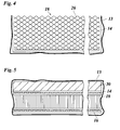
- FIG. 1 a plate-shaped shuttering element is shown with a layer structure 12, and in the FIGS. 2 to 4 a similar plate-shaped shuttering element is shown, in which the layer structure 12 is additionally covered with a shrink film 13.
- the formwork elements of the Figures 1 and 2 constructed identically and will therefore be described together below. With the exception of the film 13 corresponds to in the Figures 3 and 4 structure shown also after the formwork element FIG. 1 ,
- the layer structure 12 consists of two plates 14, 16 and a honeycomb structure 18 arranged between these plates 14, 16.
- the plates 14 and 16 each consist of a three-layered cardboard, each of the three layers containing a corrugated layer 20 and 22, respectively.
- the shaft of the shaft layer 22 of a middle layer extends transversely to the shaft of the wave layers 20 of the outer layers.
- the wave layers 20, 22 each extend between smooth layers 24.
- Walls 26 of the honeycomb structure 18 are formed by strips of paper which, as in FIG. 4 can be seen, wavy or kinked run and each together with adjacent strips to limit the honeycomb of the honeycomb structure. The edges of the walls 26 are glued to the respective adjacent plates 14, 16.
- a cavity 28 is shown which interrupts the honeycomb structure 18 and extends in a vertical direction through the formwork element to receive a peg for fixing the formwork element.
- Such cavities 28 are formed, for example, at regular intervals in the formwork element.
- the film 13 may be perforated so that the moisture released upon setting of the concrete can pass through the perforated film 13 and be absorbed by the plates 14 and 16 and the honeycomb structure 18, respectively.
- the film 13 can be pierced on the inside of the formwork element at different locations.
- FIG. 5 shows a configuration in addition to one side of the formwork element, for. B. between the plate 14 and the film 13, an insulating layer in the form of an insulating plate 30 is provided.
- the film is preferably not perforated.
- the insulating panel 30 may have any desired thickness for the purpose of thermal insulation, for example, between 30 and 120 mm, and may be made of any insulating materials such as foamed polystyrene, rock wool and the like. Instead of a rigid insulation board, a flexible insulating layer of rock wool or other suitable material can be used. Likewise, the insulating layer can also be formed from a loose bed of granules or the like, which is held by the shrink film 13 in its shape.
- the insulating layer may also have moisture-storing properties, or it may be provided in addition to the thermal barrier coating, a moisture-absorbing layer. In this case, the film 13 may be perforated again.
- the film 13 may also be dispensed with, and the insulating layer may be glued to the plate 14, for example.
Landscapes
- Engineering & Computer Science (AREA)
- Architecture (AREA)
- Mechanical Engineering (AREA)
- Civil Engineering (AREA)
- Structural Engineering (AREA)
- Forms Removed On Construction Sites Or Auxiliary Members Thereof (AREA)
- Moulds, Cores, Or Mandrels (AREA)
- Laminated Bodies (AREA)
- Building Environments (AREA)
Applications Claiming Priority (1)
| Application Number | Priority Date | Filing Date | Title |
|---|---|---|---|
| DE202008003779 | 2008-03-18 |
Publications (1)
| Publication Number | Publication Date |
|---|---|
| EP2103759A1 true EP2103759A1 (fr) | 2009-09-23 |
Family
ID=40651347
Family Applications (2)
| Application Number | Title | Priority Date | Filing Date |
|---|---|---|---|
| EP09003901A Withdrawn EP2103758A1 (fr) | 2008-03-18 | 2009-03-18 | Elément de coffrage |
| EP09003902A Withdrawn EP2103759A1 (fr) | 2008-03-18 | 2009-03-18 | Elément de coffrage |
Family Applications Before (1)
| Application Number | Title | Priority Date | Filing Date |
|---|---|---|---|
| EP09003901A Withdrawn EP2103758A1 (fr) | 2008-03-18 | 2009-03-18 | Elément de coffrage |
Country Status (2)
| Country | Link |
|---|---|
| EP (2) | EP2103758A1 (fr) |
| DE (2) | DE202009003774U1 (fr) |
Cited By (1)
| Publication number | Priority date | Publication date | Assignee | Title |
|---|---|---|---|---|
| WO2014135751A3 (fr) * | 2013-03-05 | 2015-01-15 | Pura Sakari | Moule de coulée |
Families Citing this family (1)
| Publication number | Priority date | Publication date | Assignee | Title |
|---|---|---|---|---|
| CN104675015A (zh) * | 2015-02-12 | 2015-06-03 | 伯恩太阳能科技有限公司 | 一种免拆除的建筑模板 |
Citations (9)
| Publication number | Priority date | Publication date | Assignee | Title |
|---|---|---|---|---|
| GB157429A (en) * | 1914-01-10 | 1922-05-10 | Armin Renyi | Improved building material suitable for use as a wood substitute |
| FR1093518A (fr) * | 1953-11-04 | 1955-05-05 | Cloisonnement insonore | |
| GB1220239A (en) * | 1968-02-28 | 1971-01-20 | Silcock & Colling Ltd | Improvements in or relating to packaging material and packs made therefrom |
| US3950910A (en) * | 1974-09-24 | 1976-04-20 | American Air Filter Company, Inc. | Shelter panel |
| DE3815870C1 (fr) | 1988-05-09 | 1989-08-03 | Peca-Verbundtechnik Gmbh, 8312 Dingolfing, De | |
| EP0855478A2 (fr) * | 1997-01-22 | 1998-07-29 | Graf von Montgelas, Max Joseph | Panneau composite en matière plastique et procédé pour sa fabrication |
| US5855808A (en) * | 1994-06-08 | 1999-01-05 | Damage Prevention Products Corp. | Concrete forming member |
| DE20106810U1 (de) * | 2001-03-30 | 2001-10-04 | Max Frank GmbH & Co. KG, 94339 Leiblfing | Schalungselement für den Betonbau |
| US20050275124A1 (en) * | 2004-06-14 | 2005-12-15 | Kenneth Franklin | Insulated concrete form systems and methods of making and using the same |
Family Cites Families (2)
| Publication number | Priority date | Publication date | Assignee | Title |
|---|---|---|---|---|
| US3381929A (en) * | 1963-07-24 | 1968-05-07 | Elton Ind Inc | Form assembly with adjustable retaining means for variable spacing |
| AUPQ039199A0 (en) * | 1999-05-17 | 1999-06-10 | Fisher, Geoffrey Donald | Composite panel |
-
2009
- 2009-03-18 DE DE202009003774U patent/DE202009003774U1/de not_active Expired - Lifetime
- 2009-03-18 EP EP09003901A patent/EP2103758A1/fr not_active Withdrawn
- 2009-03-18 DE DE202009003775U patent/DE202009003775U1/de not_active Expired - Lifetime
- 2009-03-18 EP EP09003902A patent/EP2103759A1/fr not_active Withdrawn
Patent Citations (9)
| Publication number | Priority date | Publication date | Assignee | Title |
|---|---|---|---|---|
| GB157429A (en) * | 1914-01-10 | 1922-05-10 | Armin Renyi | Improved building material suitable for use as a wood substitute |
| FR1093518A (fr) * | 1953-11-04 | 1955-05-05 | Cloisonnement insonore | |
| GB1220239A (en) * | 1968-02-28 | 1971-01-20 | Silcock & Colling Ltd | Improvements in or relating to packaging material and packs made therefrom |
| US3950910A (en) * | 1974-09-24 | 1976-04-20 | American Air Filter Company, Inc. | Shelter panel |
| DE3815870C1 (fr) | 1988-05-09 | 1989-08-03 | Peca-Verbundtechnik Gmbh, 8312 Dingolfing, De | |
| US5855808A (en) * | 1994-06-08 | 1999-01-05 | Damage Prevention Products Corp. | Concrete forming member |
| EP0855478A2 (fr) * | 1997-01-22 | 1998-07-29 | Graf von Montgelas, Max Joseph | Panneau composite en matière plastique et procédé pour sa fabrication |
| DE20106810U1 (de) * | 2001-03-30 | 2001-10-04 | Max Frank GmbH & Co. KG, 94339 Leiblfing | Schalungselement für den Betonbau |
| US20050275124A1 (en) * | 2004-06-14 | 2005-12-15 | Kenneth Franklin | Insulated concrete form systems and methods of making and using the same |
Cited By (1)
| Publication number | Priority date | Publication date | Assignee | Title |
|---|---|---|---|---|
| WO2014135751A3 (fr) * | 2013-03-05 | 2015-01-15 | Pura Sakari | Moule de coulée |
Also Published As
| Publication number | Publication date |
|---|---|
| DE202009003774U1 (de) | 2009-08-13 |
| EP2103758A1 (fr) | 2009-09-23 |
| DE202009003775U1 (de) | 2009-08-13 |
Similar Documents
| Publication | Publication Date | Title |
|---|---|---|
| EP0701647B1 (fr) | Element de construction | |
| DE2408028C3 (fr) | ||
| EP0065089B1 (fr) | Corps de refoulement | |
| DE60031129T2 (de) | Deckensystem mit austauschbaren platten | |
| WO2000073602A1 (fr) | Element de construction leger sous forme d'une structure en nid d'abeilles profilee a corps creux | |
| DE10214778A1 (de) | Schallabsorbierendes Paneel | |
| EP2213811A2 (fr) | Structures multicouches en tant que support pour revêtements en céramique, en pierre ou analogue | |
| DE1211370B (de) | Luftschalldaemmung dynamisch biegeweicher Schalen, wie Wandschalen, Unterdecken, Tueren, Schallabschirmmungen und Flaechenelement hierfuer | |
| EP2103759A1 (fr) | Elément de coffrage | |
| DE2658620C3 (de) | Bleibendes Schalungselement mit einer Isolierschicht | |
| DE2423384A1 (de) | Versteiftes isolierelement | |
| DE4301565A1 (de) | Bauwerk-Leichtbauelement | |
| WO2001063063A1 (fr) | Materiau calorifuge destine a etre bloque entre des cloisons | |
| DE102008059364B4 (de) | Gebäude-Schalldämmmatte | |
| EP0044467A1 (fr) | Elément de construction profilé, composant constructif pour la délimitation et le cloisonnement d'espaces réalisé à partir d'un tel élément et procédé de fabrication de ces éléments | |
| DE102007057478B4 (de) | Gebäude-Schalldämmmatte | |
| DE1084009B (de) | Verbundbauplatte | |
| CH494870A (de) | Plattenförmiges, schalldämmendes, zweischalig aufgebautes Bauelement mit Schüttgutfüllung | |
| AT292979B (de) | Plattenförmiges, schalldämmendes, zweischalig aufgebautes Bauelement mit Schüttgutfüllung | |
| EP1698452A1 (fr) | Panneau composite | |
| AT503489B1 (de) | Bauelement | |
| DE20112669U1 (de) | Schallabsorbierendes Paneel | |
| DE10232855A1 (de) | Dämmstoffelement und Gebäudewand | |
| DE10008333C2 (de) | Verfahren zum Erstellen einer gedämmten Rahmenkonstruktion sowie Dämmstoffmaterial zur Durchführung des Verfahrens | |
| DE8222182U1 (de) | Fugenbahn |
Legal Events
| Date | Code | Title | Description |
|---|---|---|---|
| PUAI | Public reference made under article 153(3) epc to a published international application that has entered the european phase |
Free format text: ORIGINAL CODE: 0009012 |
|
| 17P | Request for examination filed |
Effective date: 20090807 |
|
| AK | Designated contracting states |
Kind code of ref document: A1 Designated state(s): AT BE BG CH CY CZ DE DK EE ES FI FR GB GR HR HU IE IS IT LI LT LU LV MC MK MT NL NO PL PT RO SE SI SK TR |
|
| AX | Request for extension of the european patent |
Extension state: AL BA RS |
|
| AKX | Designation fees paid |
Designated state(s): AT BE CH DE FR LI NL |
|
| 17Q | First examination report despatched |
Effective date: 20110105 |
|
| STAA | Information on the status of an ep patent application or granted ep patent |
Free format text: STATUS: THE APPLICATION IS DEEMED TO BE WITHDRAWN |
|
| 18D | Application deemed to be withdrawn |
Effective date: 20110517 |