EP2103760A2 - Verfahren zum Steuern der Schwingungen in einem Gelenkarm zum Pumpen von Beton und zugehörige Vorrichtung - Google Patents
Verfahren zum Steuern der Schwingungen in einem Gelenkarm zum Pumpen von Beton und zugehörige Vorrichtung Download PDFInfo
- Publication number
- EP2103760A2 EP2103760A2 EP09155211A EP09155211A EP2103760A2 EP 2103760 A2 EP2103760 A2 EP 2103760A2 EP 09155211 A EP09155211 A EP 09155211A EP 09155211 A EP09155211 A EP 09155211A EP 2103760 A2 EP2103760 A2 EP 2103760A2
- Authority
- EP
- European Patent Office
- Prior art keywords
- arm
- modal
- segments
- control
- gains
- Prior art date
- Legal status (The legal status is an assumption and is not a legal conclusion. Google has not performed a legal analysis and makes no representation as to the accuracy of the status listed.)
- Granted
Links
- 238000000034 method Methods 0.000 title claims abstract description 32
- 238000005086 pumping Methods 0.000 title description 7
- 238000005259 measurement Methods 0.000 claims abstract description 21
- 238000012937 correction Methods 0.000 claims abstract description 6
- 238000011156 evaluation Methods 0.000 claims abstract description 5
- 238000010276 construction Methods 0.000 claims abstract description 4
- 238000013016 damping Methods 0.000 claims description 8
- 238000012545 processing Methods 0.000 claims 1
- 230000033001 locomotion Effects 0.000 description 31
- 239000011159 matrix material Substances 0.000 description 10
- 238000010586 diagram Methods 0.000 description 6
- 238000004364 calculation method Methods 0.000 description 4
- 238000006073 displacement reaction Methods 0.000 description 4
- 238000000053 physical method Methods 0.000 description 3
- 230000009471 action Effects 0.000 description 2
- 230000000694 effects Effects 0.000 description 2
- 239000000463 material Substances 0.000 description 2
- 230000010355 oscillation Effects 0.000 description 2
- 230000003068 static effect Effects 0.000 description 2
- 230000001133 acceleration Effects 0.000 description 1
- 238000013459 approach Methods 0.000 description 1
- 230000015572 biosynthetic process Effects 0.000 description 1
- 230000001419 dependent effect Effects 0.000 description 1
- 238000001514 detection method Methods 0.000 description 1
- 238000000605 extraction Methods 0.000 description 1
- 238000007726 management method Methods 0.000 description 1
- 230000007246 mechanism Effects 0.000 description 1
- 238000012986 modification Methods 0.000 description 1
- 230000004048 modification Effects 0.000 description 1
- 230000008569 process Effects 0.000 description 1
- 230000004044 response Effects 0.000 description 1
- 238000003786 synthesis reaction Methods 0.000 description 1
Images

Classifications
-
- E—FIXED CONSTRUCTIONS
- E04—BUILDING
- E04G—SCAFFOLDING; FORMS; SHUTTERING; BUILDING IMPLEMENTS OR AIDS, OR THEIR USE; HANDLING BUILDING MATERIALS ON THE SITE; REPAIRING, BREAKING-UP OR OTHER WORK ON EXISTING BUILDINGS
- E04G21/00—Preparing, conveying, or working-up building materials or building elements in situ; Other devices or measures for constructional work
- E04G21/02—Conveying or working-up concrete or similar masses able to be heaped or cast
- E04G21/04—Devices for both conveying and distributing
-
- B—PERFORMING OPERATIONS; TRANSPORTING
- B66—HOISTING; LIFTING; HAULING
- B66C—CRANES; LOAD-ENGAGING ELEMENTS OR DEVICES FOR CRANES, CAPSTANS, WINCHES, OR TACKLES
- B66C13/00—Other constructional features or details
- B66C13/04—Auxiliary devices for controlling movements of suspended loads, or preventing cable slack
- B66C13/06—Auxiliary devices for controlling movements of suspended loads, or preventing cable slack for minimising or preventing longitudinal or transverse swinging of loads
- B66C13/066—Auxiliary devices for controlling movements of suspended loads, or preventing cable slack for minimising or preventing longitudinal or transverse swinging of loads for minimising vibration of a boom
-
- B—PERFORMING OPERATIONS; TRANSPORTING
- B66—HOISTING; LIFTING; HAULING
- B66C—CRANES; LOAD-ENGAGING ELEMENTS OR DEVICES FOR CRANES, CAPSTANS, WINCHES, OR TACKLES
- B66C13/00—Other constructional features or details
- B66C13/18—Control systems or devices
- B66C13/40—Applications of devices for transmitting control pulses; Applications of remote control devices
-
- B—PERFORMING OPERATIONS; TRANSPORTING
- B66—HOISTING; LIFTING; HAULING
- B66C—CRANES; LOAD-ENGAGING ELEMENTS OR DEVICES FOR CRANES, CAPSTANS, WINCHES, OR TACKLES
- B66C23/00—Cranes comprising essentially a beam, boom, or triangular structure acting as a cantilever and mounted for translatory of swinging movements in vertical or horizontal planes or a combination of such movements, e.g. jib-cranes, derricks, tower cranes
-
- E—FIXED CONSTRUCTIONS
- E04—BUILDING
- E04G—SCAFFOLDING; FORMS; SHUTTERING; BUILDING IMPLEMENTS OR AIDS, OR THEIR USE; HANDLING BUILDING MATERIALS ON THE SITE; REPAIRING, BREAKING-UP OR OTHER WORK ON EXISTING BUILDINGS
- E04G21/00—Preparing, conveying, or working-up building materials or building elements in situ; Other devices or measures for constructional work
- E04G21/02—Conveying or working-up concrete or similar masses able to be heaped or cast
- E04G21/04—Devices for both conveying and distributing
- E04G21/0418—Devices for both conveying and distributing with distribution hose
- E04G21/0445—Devices for both conveying and distributing with distribution hose with booms
- E04G21/0454—Devices for both conveying and distributing with distribution hose with booms with boom vibration damper mechanisms
Definitions
- the present invention concerns a method to control the vibrations in an articulated arm for pumping concrete, and the relative device.
- the invention concerns an active control method used to reduce the vibrations to which the various segments of an articulated arm are subjected, the arm being used for pumping concrete in operating machines such as for example, pumps transported on trucks, concrete mixers or suchlike, whether they are mounted or not on trucks or trailers.
- Heavy work vehicles are known, used in the building trade, normally consisting of a truck on which an extendible arm is mounted, and/or telescopically extendible, articulated to distribute and cast concrete.
- the trucks may be equipped with concrete mixers or not.
- Extendible arms of a known type consist of a plurality of segments pivoted to each other and foldable on each other, so as to be able to assume a folded configuration close to the truck, and a working configuration in which they are extended one with respect to the other and allow to reach areas very far from the truck.
- the machine always has to act in transitory conditions between one placement and the next, or during its movement; this implies that its motion is continuously excited and dynamic variations are generated on the state of stress of the joints and in the material, which limits the working life of the machine and reduces safety for the operators.
- a known device which has the function of damping the vibrations of an articulated arm is described in US-B2-7,143,682 .
- a compensation mechanism is provided, on the side of the drive system, to compensate a disturbance which has determined a movement of the arm with respect to the position envisaged: the disturbance may consist for example of the fluctuations in pressure at which the concrete is delivered.
- US'682 is specifically directed to the uncontrolled movements of the arm, or of one or more of its segments, that are generated during the phase of delivery of the concrete, particularly due to the cyclical loads to which the concrete distribution arm is subjected in the phase of delivery and which have the effect of making the entire arm perform a vibration motion.
- this document does not provide to built and use a theoretical numerical model able to represent the condition of the arm and/or of its segments when it/they is/are subjected to the movement by the operator to move the arm in the position of delivery of the concrete before starting the concrete delivery step.
- Purpose of the invention is therefore to obtain a perfected method of active control of the vibrations of an articulated arm, which allows to correct and compensate the vibrations.
- the active control method for damping the vibrations of an articulated arm for pumping concrete bases its functioning logic on the fact that the main difficulty in implementing an active control consists substantially of two points:
- Another point that is to be considered is that in order to dampen the vibrations in one specific point, for example the tip of the arm from which the concrete is delivered, is necessary to consider the contribution to the vibration of all the segments of the arms, including both the component due to the positioning movement imparted by the operator and the component due to the vibrations which are superimposed to the movement imparted by the operator.
- a further point to be considered is that the present invention is aimed to control the vibrations in a specific point which can be located along the whole length of the arm, not only the final segment involved in the delivery of the concrete. In fact, the case may be, it can be necessary to control also an intermediate point of the arm, for example if the arm is introduced with a median part thereof inside a window, or the arm is moved near a tree, a building or the like.
- the present invention substantially consists of an active control method and an electronic control device which performs said method, and which implement a control logic based on:
- the aforesaid one or more instruments are configured to acquire data related to the behavior of the arm and of all of its segments along its whole length, not only in a specific end point thereof.
- the control logic of the vibrations therefore acts by means of a feedback force which is added to the command given by the operator for the movement of the whole arm, if he intervenes during a command, or determining a compensation force also with the arm stationary during a pumping operation which itself causes vibrations.
- the rigid movement (hereafter denominated "broad motion") of the arms is in any case entrusted to the control of the operator, whereas the active control of the vibrations of the whole arm acts in the form of an additional command, which is superimposed to the command of the operator, with the task of damping the oscillations of the whole structure of the arm in order to make the whole arm moving following the theoretical movement commanded by the operator.
- the main objective of the active control method according to the present invention is to contain the oscillations of the structure associated with the first modes of vibrating which mainly participate in the increase of the dynamic load.
- the modes with higher frequency in fact, have a higher damping and therefore do not contribute appreciably to the motion.
- the operation to damp the vibrations is made by using a control determined on the basis of a numerical model which is based, for its implementation and application, on a reference model written in the form of the modes of the structure (modal model).
- the numerical modal model is constructed starting from experimental data or from structural models available to the designer.
- the state variables which describe the system are no longer physical variables (displacements and speed) but modal variables, and represent the "measurement” of how much each mode of vibrating participates, also according to the broad motion imparted by manual control, in the overall motion of the arm.
- This numerical modal model although formed by a limited number of degrees of freedom, in any case constitutes an optimum approximation of the complete numerical model, but is much simpler to manage from the point of view of the computational load.
- the calculation is performed by setting the position of the poles of the system in the complex Gauss plane.
- the objective is to increase the damping of the system (or the real part of the auto-values only).
- the gains will be expressed as a function of the position assumed by the arm during the broad motion. For this reason they must be tabulated and registered in pre-memorized tables, and then introduced into the control system using a procedure of linearization in segments.
- the electronic controller according to the position detected, interpolates the gains values memorized and uses these values in a feedback control logic between the reference state that coincides with the broad motion alone, due for example to the command by the operator (therefore without vibratory motions), and the current vibrations, which are described by the modal coordinates.
- the gains thus calculated therefore multiply the difference between the reference modal coordinates (nil) and those measured (or estimated), and allow to determine the control forces to be applied, by means of the relative actuators, to the arm or to at least part of the relative segments.
- the last step provides to evaluate the modal coordinates not directly measurable.
- control system for this function the control system according to the invention provides to use a state estimator.
- the modal coordinates cannot be traced back directly to any physical measurement, therefore they are not directly measurable.
- the problem therefore arises of estimating the coordinates starting from the measurements available (accelerometers, strain gauges, elongations of the actuators, ).
- the estimator receives as input the measurements and the known forces acting on the real arm and supplies as output the estimate of the modal coordinates.
- the estimator also works starting from the knowledge of the reduced modal model: inside it there are the matrixes which characterize the system, according to the position assumed.
- the estimator compares the estimated measurements (calculated by multiplying the modal coordinates estimated by a suitable matrix, as will be seen better hereafter) with the real ones, then correcting the estimate so that it converges on the real values.
- the correction is made by multiplying the difference between measurement and estimate by a suitable set of gains.
- the gains can be determined by means of various and different methods; in order to calculate the gains, a preferential solution provides to adopt the "Kalman Filter” or other analogous or similar calculation method.
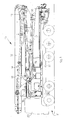
- an extendible articulated arm 10 able to distribute concrete or analogous material for the building trade, is shown in its assembled position on a heavy work vehicle 11, in its folded condition, for transport.
- the heavy vehicle 11 comprises a driver's cabin 20, and a supporting frame 21 on which the arm 10 is mounted.
- the extendible arm 10 comprises a plurality of segments articulated, for example, in the embodiment shown, in six segments, respectively a first 12, a second 13, a third 14, a fourth 15, a fifth 16 and a sixth 17, pivoted to each other at the respective ends.
- the totality of the articulated segments 12-17 can be rotated, even up to 360°, with respect to the vertical axis of the vehicle 11.
- the first segment 12 is, in a known manner, pivoted to a turret 18, and can be rotated with respect thereto by means of its own actuator.
- the other segments 13-17 are sequentially pivoted to each other at respective ends and can be individually driven, by means of their own actuators, indicated in their entirety by the reference number 40 in the diagram in fig. 4 , according to specific requirements.
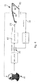
- a block diagram is shown of the active control method to control the vibrations of the articulated arm 10 according to the present invention, using an electronic controller 25 and a state estimator 26.
- the method according to the invention provides a step of constructing a reduced numerical modal model 27 constructed starting from experimental data or from structural models available to the designer.
- the reduced numerical modal model 27 constitutes an optimum approximation of the complete model, and is easy to manage from the point of view of the computational load.
- a second step in the method provides to evaluate the gains of the states controller 25 through the reduced modal model (different for every configuration achieved by the machine during the broad motion), setting the position of the poles, indicated by the reference number 28, of the system in the complex Gauss plane.
- the objective is to increase the damping of the system.
- the gains are expressed as a function of the actual position assumed by the articulated arm 10 during the broad motion, and according to the value of force 29 actually transmitted to the arm 10 by the operator, which force 29 is added to the feedback control values, as better explained hereafter, in an adder 30.
- the purpose of the control of the vibrations is to define the matrix of gains [G] which, starting from the state of the system, provides a feedback control action so as to limit said vibrations, following the logic diagram shown in fig. 4 .
- the matrix of gains [G] can be calculated using the calculation process described hereafter.
- the electronic controller 25 interpolates the values of gains memorized, and uses these values in a feedback control logic between the reference state q rif , which coincides with the broad motion only (therefore without vibratory motions) and the current vibrations q , which are described, however, by the modal coordinates.
- the gains thus calculated therefore multiply the difference between the reference modal coordinates (nil) and those measured (or estimated), and allow to determine the control forces to be applied by means of the relative actuators, to the arm 10, or to at least part of the relative segments.
- the last step provides to evaluate the modal coordinates not directly measurable.
- controller 25 provides to use a state estimator 26.
- the estimator 26 receives as input, from said sensors 31, the measurements, indicated by the reference number 32, and the known forces, indicated by the reference number 33, actually acting on the arm 10, and supplies as output the estimate of the modal coordinates in terms of estimated state 44.
- the estimator 26 also operates starting from the knowledge of the reduced modal model 27.
- the estimated measurements are then compared, in an adder 37, with the real measurements 32, then the estimate is corrected so that it converges on the real values.
- the correction is made by the estimator 26 by multiplying the difference between measurements 32 and estimates 38 by a suitable set of gains 35, for example obtained with the Kalman Filter.
Landscapes
- Engineering & Computer Science (AREA)
- Mechanical Engineering (AREA)
- Architecture (AREA)
- Civil Engineering (AREA)
- Structural Engineering (AREA)
- Automation & Control Theory (AREA)
- Manipulator (AREA)
- On-Site Construction Work That Accompanies The Preparation And Application Of Concrete (AREA)
- Feedback Control In General (AREA)
- Numerical Control (AREA)
Applications Claiming Priority (1)
| Application Number | Priority Date | Filing Date | Title |
|---|---|---|---|
| IT000057A ITUD20080057A1 (it) | 2008-03-17 | 2008-03-17 | Procedimento di controllo delle vibrazioni di un braccio articolato per il pompaggio di calcestruzzo, e relativo dispositivo |
Publications (3)
| Publication Number | Publication Date |
|---|---|
| EP2103760A2 true EP2103760A2 (de) | 2009-09-23 |
| EP2103760A3 EP2103760A3 (de) | 2010-04-07 |
| EP2103760B1 EP2103760B1 (de) | 2017-09-20 |
Family
ID=40293331
Family Applications (1)
| Application Number | Title | Priority Date | Filing Date |
|---|---|---|---|
| EP09155211.7A Not-in-force EP2103760B1 (de) | 2008-03-17 | 2009-03-16 | Verfahren zum Steuern der Schwingungen in einem Gelenkarm zum Pumpen von Beton und zugehörige Vorrichtung |
Country Status (4)
| Country | Link |
|---|---|
| US (1) | US8082083B2 (de) |
| EP (1) | EP2103760B1 (de) |
| CN (1) | CN101538941B (de) |
| IT (1) | ITUD20080057A1 (de) |
Cited By (11)
| Publication number | Priority date | Publication date | Assignee | Title |
|---|---|---|---|---|
| EP2347988A1 (de) | 2010-01-26 | 2011-07-27 | Cifa S.P.A. | Vorrichtung zur aktiven Kontrolle der Vibrationen eines Gelenkauslegers zum Pumpen von Beton. |
| CN103175572A (zh) * | 2011-12-23 | 2013-06-26 | 中联重科股份有限公司 | 混凝土泵送设备状态监测与故障诊断系统 |
| ITMI20120362A1 (it) * | 2012-03-07 | 2013-09-08 | Cifa Spa | Procedimento per il controllo delle vibrazioni di un braccio articolato e relativo apparato |
| ITMI20121903A1 (it) * | 2012-11-08 | 2014-05-09 | Cifa Spa | Apparato, e relativo metodo, per il controllo delle vibrazioni di un braccio articolato |
| AT514116A1 (de) * | 2013-04-09 | 2014-10-15 | Ttcontrol Gmbh | Regelsystem und Verfahren zum Steuern der Orientierung eines Segments eines Manipulators |
| EP2778466A4 (de) * | 2011-10-20 | 2015-09-23 | Zoomlion Heavy Ind Sci & Tech | Pumpwagen und verfahren dafür, steuerung und vorrichtung zur auslegungsschwingung des pumpwagens |
| DE102018109088A1 (de) | 2018-04-17 | 2019-10-17 | Liebherr-Mischtechnik Gmbh | Großmanipulator, insbesondere für Betonpumpen |
| DE102018109057A1 (de) | 2018-04-17 | 2019-10-17 | Liebherr-Mischtechnik Gmbh | Betonpumpe |
| DE102018109098A1 (de) | 2018-04-17 | 2019-10-17 | Liebherr-Mischtechnik Gmbh | Betonpumpe |
| EP3566998A1 (de) * | 2018-05-11 | 2019-11-13 | ABB Schweiz AG | Steuerung von brückenkränen |
| WO2021047872A1 (de) * | 2019-09-13 | 2021-03-18 | Putzmeister Engineering Gmbh | Verfahren zum betreiben einer arbeitsmaschine und arbeitsmaschine |
Families Citing this family (20)
| Publication number | Priority date | Publication date | Assignee | Title |
|---|---|---|---|---|
| WO2010101233A1 (ja) * | 2009-03-06 | 2010-09-10 | 株式会社小松製作所 | 建設機械、建設機械の制御方法、及びこの方法をコンピュータに実行させるプログラム |
| IT1398899B1 (it) * | 2010-03-12 | 2013-03-21 | Cifa Spa | Braccio di distribuzione di calcestruzzo e relativo procedimento di realizzazione |
| CN101982636B (zh) * | 2010-09-19 | 2011-12-21 | 三一重工股份有限公司 | 一种泵送机械 |
| CN101956459B (zh) * | 2010-09-19 | 2011-12-21 | 三一重工股份有限公司 | 一种泵送机械 |
| CN102108790B (zh) * | 2010-12-24 | 2012-01-04 | 三一重工股份有限公司 | 混凝土泵送设备及其臂架状态控制系统 |
| CN103090964A (zh) * | 2011-12-15 | 2013-05-08 | 中联重科股份有限公司 | 臂架振动监测的车载数据单元、方法、工程机械及系统 |
| CN103104451B (zh) * | 2011-12-23 | 2013-11-20 | 中联重科股份有限公司 | 泵送排量控制器、泵车及泵送排量控制方法 |
| CN103104096B (zh) * | 2011-12-23 | 2013-10-23 | 中联重科股份有限公司 | 用于泵车的最大许可泵送排量数据库建立方法 |
| CN102707730B (zh) * | 2012-04-05 | 2014-09-03 | 大连理工大学 | 高空作业车操作平台轨迹控制装置 |
| CN105593438B (zh) * | 2013-05-31 | 2019-07-05 | 伊顿智能动力有限公司 | 用于通过平衡保护来降低动臂跳动的液压系统及方法 |
| CN105637232B (zh) | 2013-08-30 | 2018-06-19 | 伊顿公司 | 使用一对独立液压计量阀降低动臂振荡的控制方法和系统 |
| WO2015073329A1 (en) | 2013-11-14 | 2015-05-21 | Eaton Corporation | Pilot control mechanism for boom bounce reduction |
| EP3069043B1 (de) | 2013-11-14 | 2019-02-27 | Eaton Corporation | Steuerungsstrategie zur reduzierung einer auslegerschwingung |
| CN106661894B (zh) | 2014-07-15 | 2019-12-10 | 伊顿公司 | 实现悬臂弹跳减少以及防止液压系统中的非指令运动的方法和设备 |
| CN104847113B (zh) * | 2014-12-12 | 2017-02-22 | 北汽福田汽车股份有限公司 | 一种臂架控制方法 |
| EP3615813A4 (de) | 2017-04-28 | 2021-01-27 | Eaton Intelligent Power Limited | System mit bewegungssensoren zur dämpfung von masseninduzierten schwingungen in maschinen |
| EP3615814A4 (de) | 2017-04-28 | 2021-01-27 | Eaton Intelligent Power Limited | System zur dämpfung von masseninduzierten schwingungen in maschinen mit hydraulisch gesteuerten auslegern oder länglichen elementen |
| DE102018201411A1 (de) * | 2018-01-30 | 2019-08-01 | Robert Bosch Gmbh | Verfahren zum Ermitteln eines zeitlichen Verlaufs einer Messgröße, Prognosesystem, Aktorsteuerungssystem, Verfahren zum Trainieren des Aktorsteuerungssystems,Trainingssystem, Computerprogramm und maschinenlesbares Speichermedium |
| CN113775179A (zh) * | 2021-10-13 | 2021-12-10 | 新乡市畅想智能机电有限公司 | 混凝土泵车3d打印控制方法及系统 |
| DE102022211081A1 (de) * | 2022-10-19 | 2024-04-25 | Putzmeister Engineering Gmbh | Verfahren und System zum Betreiben eines Baustoffsystems |
Citations (3)
| Publication number | Priority date | Publication date | Assignee | Title |
|---|---|---|---|---|
| JPH07133094A (ja) | 1993-11-10 | 1995-05-23 | Mitsubishi Heavy Ind Ltd | ブームの制振装置 |
| JP2000282687A (ja) | 1999-03-31 | 2000-10-10 | Ishikawajima Constr Mach Co | ブーム付コンクリートポンプ車の運転制御装置 |
| US7143682B2 (en) | 2001-01-15 | 2006-12-05 | Schwing Gmbh | Large manipulator having a vibration damping capacity |
Family Cites Families (9)
| Publication number | Priority date | Publication date | Assignee | Title |
|---|---|---|---|---|
| SE459878B (sv) * | 1985-01-07 | 1989-08-14 | Akermans Verkstad Ab | Foerfarande och anordning foer att reducera kolvhastigheten i speciellt en arbetsmaskins kolv- och cylinderaggregat |
| FR2670705B1 (fr) | 1990-12-21 | 1993-04-09 | Bertin & Cie | Procede et commande d'un systeme mecanique flexible motorise a configuration variable, tel qu'un bras robot par exemple. |
| US5560431A (en) * | 1995-07-21 | 1996-10-01 | Caterpillar Inc. | Site profile based control system and method for an earthmoving implement |
| DE10016137C2 (de) | 2000-03-31 | 2003-08-21 | Iveco Magirus | Drehleiter |
| DE10016136C2 (de) | 2000-03-31 | 2003-08-21 | Iveco Magirus | Drehleiter-Regelung |
| JP4647325B2 (ja) * | 2004-02-10 | 2011-03-09 | 株式会社小松製作所 | 建設機械の作業機の制御装置、建設機械の作業機の制御方法、及びこの方法をコンピュータに実行させるプログラム |
| DE102004012945A1 (de) * | 2004-03-17 | 2005-10-13 | Cnh Baumaschinen Gmbh | Vorrichtung und Verfahren zur Bewegungstilgung bei Baumaschinen |
| DE102005042721A1 (de) | 2005-09-08 | 2007-03-15 | Iveco Magirus Ag | Gelenkleiter oder Hubbühne mit Bahnsteuerung und aktiver Schwingungsdämpfung |
| US7748147B2 (en) * | 2007-04-30 | 2010-07-06 | Deere & Company | Automated control of boom or attachment for work vehicle to a present position |
-
2008
- 2008-03-17 IT IT000057A patent/ITUD20080057A1/it unknown
-
2009
- 2009-03-13 US US12/403,920 patent/US8082083B2/en active Active
- 2009-03-16 EP EP09155211.7A patent/EP2103760B1/de not_active Not-in-force
- 2009-03-17 CN CN2009101271936A patent/CN101538941B/zh not_active Expired - Fee Related
Patent Citations (3)
| Publication number | Priority date | Publication date | Assignee | Title |
|---|---|---|---|---|
| JPH07133094A (ja) | 1993-11-10 | 1995-05-23 | Mitsubishi Heavy Ind Ltd | ブームの制振装置 |
| JP2000282687A (ja) | 1999-03-31 | 2000-10-10 | Ishikawajima Constr Mach Co | ブーム付コンクリートポンプ車の運転制御装置 |
| US7143682B2 (en) | 2001-01-15 | 2006-12-05 | Schwing Gmbh | Large manipulator having a vibration damping capacity |
Cited By (23)
| Publication number | Priority date | Publication date | Assignee | Title |
|---|---|---|---|---|
| US8925310B2 (en) | 2010-01-26 | 2015-01-06 | Cifa Spa | Device to actively control the vibrations of an articulated arm to pump concrete |
| EP2347988A1 (de) | 2010-01-26 | 2011-07-27 | Cifa S.P.A. | Vorrichtung zur aktiven Kontrolle der Vibrationen eines Gelenkauslegers zum Pumpen von Beton. |
| EP2778466B1 (de) | 2011-10-20 | 2022-06-08 | Zoomlion Heavy Industry Science and Technology Co., Ltd. | Pumpwagen und verfahren dafür, steuerung und vorrichtung zur auslegungsschwingung des pumpwagens |
| EP2778466A4 (de) * | 2011-10-20 | 2015-09-23 | Zoomlion Heavy Ind Sci & Tech | Pumpwagen und verfahren dafür, steuerung und vorrichtung zur auslegungsschwingung des pumpwagens |
| CN103175572A (zh) * | 2011-12-23 | 2013-06-26 | 中联重科股份有限公司 | 混凝土泵送设备状态监测与故障诊断系统 |
| WO2013091538A1 (zh) * | 2011-12-23 | 2013-06-27 | 中联重科股份有限公司 | 混凝土泵送设备状态监测与故障诊断系统 |
| CN103175572B (zh) * | 2011-12-23 | 2016-03-09 | 中联重科股份有限公司 | 混凝土泵送设备状态监测与故障诊断系统 |
| ITMI20120362A1 (it) * | 2012-03-07 | 2013-09-08 | Cifa Spa | Procedimento per il controllo delle vibrazioni di un braccio articolato e relativo apparato |
| WO2013132303A1 (en) * | 2012-03-07 | 2013-09-12 | Cifa Spa | Method to control the vibrations of an articulated arm and corresponding apparatus |
| ITMI20121903A1 (it) * | 2012-11-08 | 2014-05-09 | Cifa Spa | Apparato, e relativo metodo, per il controllo delle vibrazioni di un braccio articolato |
| CN103807351A (zh) * | 2012-11-08 | 2014-05-21 | 西法股份公司 | 控制关节臂的振动的装置和相应的方法 |
| CN103807351B (zh) * | 2012-11-08 | 2017-07-18 | 西法股份公司 | 控制关节臂的振动的装置和相应的方法 |
| EP2730531A1 (de) * | 2012-11-08 | 2014-05-14 | Cifa S.P.A. | Vorrichtung und zugehöriges Verfahren zur Steuerung der Vibrationen eines Gelenkauslegers |
| WO2014165889A1 (de) * | 2013-04-09 | 2014-10-16 | Ttcontrol Gmbh | Regelsystem und verfahren zum steuern der orientierung eines segments eines manipulators |
| AT514116A1 (de) * | 2013-04-09 | 2014-10-15 | Ttcontrol Gmbh | Regelsystem und Verfahren zum Steuern der Orientierung eines Segments eines Manipulators |
| US10106994B2 (en) | 2013-04-09 | 2018-10-23 | Ttcontrol Gmbh | Control system and method for controlling the orientation of a segment of a manipulator |
| DE102018109057A1 (de) | 2018-04-17 | 2019-10-17 | Liebherr-Mischtechnik Gmbh | Betonpumpe |
| DE102018109098A1 (de) | 2018-04-17 | 2019-10-17 | Liebherr-Mischtechnik Gmbh | Betonpumpe |
| DE102018109088A1 (de) | 2018-04-17 | 2019-10-17 | Liebherr-Mischtechnik Gmbh | Großmanipulator, insbesondere für Betonpumpen |
| EP3566998A1 (de) * | 2018-05-11 | 2019-11-13 | ABB Schweiz AG | Steuerung von brückenkränen |
| US11305969B2 (en) | 2018-05-11 | 2022-04-19 | Abb Schweiz Ag | Control of overhead cranes |
| WO2021047872A1 (de) * | 2019-09-13 | 2021-03-18 | Putzmeister Engineering Gmbh | Verfahren zum betreiben einer arbeitsmaschine und arbeitsmaschine |
| US12215509B2 (en) | 2019-09-13 | 2025-02-04 | Putzmeister Engineering Gmbh | Method for operating a working machine, and working machine |
Also Published As
| Publication number | Publication date |
|---|---|
| ITUD20080057A1 (it) | 2009-09-18 |
| CN101538941B (zh) | 2012-11-07 |
| US8082083B2 (en) | 2011-12-20 |
| EP2103760A3 (de) | 2010-04-07 |
| US20090229457A1 (en) | 2009-09-17 |
| EP2103760B1 (de) | 2017-09-20 |
| CN101538941A (zh) | 2009-09-23 |
Similar Documents
| Publication | Publication Date | Title |
|---|---|---|
| EP2103760B1 (de) | Verfahren zum Steuern der Schwingungen in einem Gelenkarm zum Pumpen von Beton und zugehörige Vorrichtung | |
| CN105717947B (zh) | 控制空中装置的方法和有实现此方法的控制器的空中装置 | |
| JP4795228B2 (ja) | ロープ吊りの荷物を取り扱う最適動き案内付きクレーンまたはショベル | |
| US9651112B2 (en) | Vibration suppression method, controller, device of boom and pump truck | |
| US11668077B2 (en) | System and method for determining the mass of a payload moved by a working device | |
| JP2011079674A (ja) | クレーンのホイストケーブルによって運ばれる負荷の負荷質量を決定するためのシステム | |
| JP7762227B2 (ja) | 車両接続式の吊り上げ装置を開ループ制御および/または閉ループ制御するための方法 | |
| IT201800007173A1 (it) | Sistema di identificazione e controllo attivo di vibrazioni in una struttura, e relativo metodo | |
| Kilicslan et al. | Tipping loads of mobile cranes with flexible booms | |
| JP6972971B2 (ja) | 制御システム、機械学習装置、メンテナンス支援装置、及びメンテナンス支援方法 | |
| Wanner et al. | A lumped parameter model of the boom of a mobile concrete pump | |
| KR20200135795A (ko) | 진동 댐퍼를 가진 대형 매니풀레이터 | |
| Zimmert et al. | 2-DOF control of a fire-rescue turntable ladder | |
| CN111015661B (zh) | 一种机器人柔性负载主动振动控制方法和系统 | |
| Veciana et al. | Minimizing residual vibrations for non-zero initial states: Application to an emergency stop of a crane | |
| JP6297362B2 (ja) | 振動試験装置 | |
| KR101209779B1 (ko) | 로봇의 부하 추정 방법 | |
| Alobaid et al. | Robust input shaping for residual vibration suppression in overhead crane systems with suspended beams: F. Alobaid et al. | |
| JP2000170380A (ja) | ブーム制振装置 | |
| CN104344939A (zh) | 用于测定与结构损伤有关的参数的方法 | |
| CN116576173B (zh) | 确定液压缸的驱动力的方法、装置及系统 | |
| EP2199880A1 (de) | Verfahren und System zur Positionschätzung einer Reihe von Gelenkelementen | |
| Zorn et al. | Control stabilization of multilink manipulators in a truck-mounted concrete boom pump | |
| Burtseva et al. | Vibration control for high-rise constructions | |
| US10890499B2 (en) | System and method for predicting strain power spectral densities of light machine structure |
Legal Events
| Date | Code | Title | Description |
|---|---|---|---|
| PUAI | Public reference made under article 153(3) epc to a published international application that has entered the european phase |
Free format text: ORIGINAL CODE: 0009012 |
|
| AK | Designated contracting states |
Kind code of ref document: A2 Designated state(s): AT BE BG CH CY CZ DE DK EE ES FI FR GB GR HR HU IE IS IT LI LT LU LV MC MK MT NL NO PL PT RO SE SI SK TR |
|
| AX | Request for extension of the european patent |
Extension state: AL BA RS |
|
| RIN1 | Information on inventor provided before grant (corrected) |
Inventor name: RESTA, FERRUCCIO Inventor name: PIRRI, NICOLA Inventor name: MAINI, PAOLO DARIO Inventor name: RIPAMONTI, FRANCESCO Inventor name: TOSI, ALESSANDRO |
|
| PUAL | Search report despatched |
Free format text: ORIGINAL CODE: 0009013 |
|
| AK | Designated contracting states |
Kind code of ref document: A3 Designated state(s): AT BE BG CH CY CZ DE DK EE ES FI FR GB GR HR HU IE IS IT LI LT LU LV MC MK MT NL NO PL PT RO SE SI SK TR |
|
| AX | Request for extension of the european patent |
Extension state: AL BA RS |
|
| 17P | Request for examination filed |
Effective date: 20100929 |
|
| 17Q | First examination report despatched |
Effective date: 20101118 |
|
| AKX | Designation fees paid |
Designated state(s): AT BE BG CH CY CZ DE DK EE ES FI FR GB GR HR HU IE IS IT LI LT LU LV MC MK MT NL NO PL PT RO SE SI SK TR |
|
| GRAP | Despatch of communication of intention to grant a patent |
Free format text: ORIGINAL CODE: EPIDOSNIGR1 |
|
| INTG | Intention to grant announced |
Effective date: 20170412 |
|
| GRAS | Grant fee paid |
Free format text: ORIGINAL CODE: EPIDOSNIGR3 |
|
| GRAA | (expected) grant |
Free format text: ORIGINAL CODE: 0009210 |
|
| AK | Designated contracting states |
Kind code of ref document: B1 Designated state(s): AT BE BG CH CY CZ DE DK EE ES FI FR GB GR HR HU IE IS IT LI LT LU LV MC MK MT NL NO PL PT RO SE SI SK TR |
|
| REG | Reference to a national code |
Ref country code: GB Ref legal event code: FG4D |
|
| RIN1 | Information on inventor provided before grant (corrected) |
Inventor name: PIRRI, NICOLA Inventor name: TOSI, ALESSANDRO Inventor name: RIPAMONTI, FRANCESCO Inventor name: MAINI, PAOLO DARIO Inventor name: RESTA, FERRUCCIO |
|
| REG | Reference to a national code |
Ref country code: CH Ref legal event code: EP |
|
| REG | Reference to a national code |
Ref country code: AT Ref legal event code: REF Ref document number: 930235 Country of ref document: AT Kind code of ref document: T Effective date: 20171015 |
|
| REG | Reference to a national code |
Ref country code: IE Ref legal event code: FG4D |
|
| REG | Reference to a national code |
Ref country code: DE Ref legal event code: R096 Ref document number: 602009048414 Country of ref document: DE |
|
| REG | Reference to a national code |
Ref country code: CH Ref legal event code: NV Representative=s name: MICHELI AND CIE SA, CH |
|
| REG | Reference to a national code |
Ref country code: NL Ref legal event code: FP |
|
| PG25 | Lapsed in a contracting state [announced via postgrant information from national office to epo] |
Ref country code: HR Free format text: LAPSE BECAUSE OF FAILURE TO SUBMIT A TRANSLATION OF THE DESCRIPTION OR TO PAY THE FEE WITHIN THE PRESCRIBED TIME-LIMIT Effective date: 20170920 Ref country code: FI Free format text: LAPSE BECAUSE OF FAILURE TO SUBMIT A TRANSLATION OF THE DESCRIPTION OR TO PAY THE FEE WITHIN THE PRESCRIBED TIME-LIMIT Effective date: 20170920 Ref country code: SE Free format text: LAPSE BECAUSE OF FAILURE TO SUBMIT A TRANSLATION OF THE DESCRIPTION OR TO PAY THE FEE WITHIN THE PRESCRIBED TIME-LIMIT Effective date: 20170920 Ref country code: NO Free format text: LAPSE BECAUSE OF FAILURE TO SUBMIT A TRANSLATION OF THE DESCRIPTION OR TO PAY THE FEE WITHIN THE PRESCRIBED TIME-LIMIT Effective date: 20171220 Ref country code: LT Free format text: LAPSE BECAUSE OF FAILURE TO SUBMIT A TRANSLATION OF THE DESCRIPTION OR TO PAY THE FEE WITHIN THE PRESCRIBED TIME-LIMIT Effective date: 20170920 |
|
| REG | Reference to a national code |
Ref country code: LT Ref legal event code: MG4D |
|
| PG25 | Lapsed in a contracting state [announced via postgrant information from national office to epo] |
Ref country code: BG Free format text: LAPSE BECAUSE OF FAILURE TO SUBMIT A TRANSLATION OF THE DESCRIPTION OR TO PAY THE FEE WITHIN THE PRESCRIBED TIME-LIMIT Effective date: 20171220 Ref country code: GR Free format text: LAPSE BECAUSE OF FAILURE TO SUBMIT A TRANSLATION OF THE DESCRIPTION OR TO PAY THE FEE WITHIN THE PRESCRIBED TIME-LIMIT Effective date: 20171221 Ref country code: LV Free format text: LAPSE BECAUSE OF FAILURE TO SUBMIT A TRANSLATION OF THE DESCRIPTION OR TO PAY THE FEE WITHIN THE PRESCRIBED TIME-LIMIT Effective date: 20170920 |
|
| REG | Reference to a national code |
Ref country code: FR Ref legal event code: PLFP Year of fee payment: 10 |
|
| PG25 | Lapsed in a contracting state [announced via postgrant information from national office to epo] |
Ref country code: CZ Free format text: LAPSE BECAUSE OF FAILURE TO SUBMIT A TRANSLATION OF THE DESCRIPTION OR TO PAY THE FEE WITHIN THE PRESCRIBED TIME-LIMIT Effective date: 20170920 Ref country code: ES Free format text: LAPSE BECAUSE OF FAILURE TO SUBMIT A TRANSLATION OF THE DESCRIPTION OR TO PAY THE FEE WITHIN THE PRESCRIBED TIME-LIMIT Effective date: 20170920 Ref country code: PL Free format text: LAPSE BECAUSE OF FAILURE TO SUBMIT A TRANSLATION OF THE DESCRIPTION OR TO PAY THE FEE WITHIN THE PRESCRIBED TIME-LIMIT Effective date: 20170920 Ref country code: RO Free format text: LAPSE BECAUSE OF FAILURE TO SUBMIT A TRANSLATION OF THE DESCRIPTION OR TO PAY THE FEE WITHIN THE PRESCRIBED TIME-LIMIT Effective date: 20170920 |
|
| PG25 | Lapsed in a contracting state [announced via postgrant information from national office to epo] |
Ref country code: EE Free format text: LAPSE BECAUSE OF FAILURE TO SUBMIT A TRANSLATION OF THE DESCRIPTION OR TO PAY THE FEE WITHIN THE PRESCRIBED TIME-LIMIT Effective date: 20170920 Ref country code: SK Free format text: LAPSE BECAUSE OF FAILURE TO SUBMIT A TRANSLATION OF THE DESCRIPTION OR TO PAY THE FEE WITHIN THE PRESCRIBED TIME-LIMIT Effective date: 20170920 Ref country code: IS Free format text: LAPSE BECAUSE OF FAILURE TO SUBMIT A TRANSLATION OF THE DESCRIPTION OR TO PAY THE FEE WITHIN THE PRESCRIBED TIME-LIMIT Effective date: 20180120 |
|
| REG | Reference to a national code |
Ref country code: DE Ref legal event code: R097 Ref document number: 602009048414 Country of ref document: DE |
|
| PLBE | No opposition filed within time limit |
Free format text: ORIGINAL CODE: 0009261 |
|
| STAA | Information on the status of an ep patent application or granted ep patent |
Free format text: STATUS: NO OPPOSITION FILED WITHIN TIME LIMIT |
|
| PG25 | Lapsed in a contracting state [announced via postgrant information from national office to epo] |
Ref country code: DK Free format text: LAPSE BECAUSE OF FAILURE TO SUBMIT A TRANSLATION OF THE DESCRIPTION OR TO PAY THE FEE WITHIN THE PRESCRIBED TIME-LIMIT Effective date: 20170920 |
|
| 26N | No opposition filed |
Effective date: 20180621 |
|
| PG25 | Lapsed in a contracting state [announced via postgrant information from national office to epo] |
Ref country code: SI Free format text: LAPSE BECAUSE OF FAILURE TO SUBMIT A TRANSLATION OF THE DESCRIPTION OR TO PAY THE FEE WITHIN THE PRESCRIBED TIME-LIMIT Effective date: 20170920 Ref country code: MC Free format text: LAPSE BECAUSE OF FAILURE TO SUBMIT A TRANSLATION OF THE DESCRIPTION OR TO PAY THE FEE WITHIN THE PRESCRIBED TIME-LIMIT Effective date: 20170920 |
|
| REG | Reference to a national code |
Ref country code: IE Ref legal event code: MM4A |
|
| PG25 | Lapsed in a contracting state [announced via postgrant information from national office to epo] |
Ref country code: LU Free format text: LAPSE BECAUSE OF NON-PAYMENT OF DUE FEES Effective date: 20180316 |
|
| PG25 | Lapsed in a contracting state [announced via postgrant information from national office to epo] |
Ref country code: IE Free format text: LAPSE BECAUSE OF NON-PAYMENT OF DUE FEES Effective date: 20180316 |
|
| REG | Reference to a national code |
Ref country code: AT Ref legal event code: UEP Ref document number: 930235 Country of ref document: AT Kind code of ref document: T Effective date: 20170920 |
|
| PG25 | Lapsed in a contracting state [announced via postgrant information from national office to epo] |
Ref country code: MT Free format text: LAPSE BECAUSE OF NON-PAYMENT OF DUE FEES Effective date: 20180316 |
|
| PG25 | Lapsed in a contracting state [announced via postgrant information from national office to epo] |
Ref country code: TR Free format text: LAPSE BECAUSE OF FAILURE TO SUBMIT A TRANSLATION OF THE DESCRIPTION OR TO PAY THE FEE WITHIN THE PRESCRIBED TIME-LIMIT Effective date: 20170920 |
|
| PGFP | Annual fee paid to national office [announced via postgrant information from national office to epo] |
Ref country code: IT Payment date: 20200310 Year of fee payment: 12 Ref country code: NL Payment date: 20200319 Year of fee payment: 12 Ref country code: DE Payment date: 20200320 Year of fee payment: 12 Ref country code: AT Payment date: 20200320 Year of fee payment: 12 Ref country code: GB Payment date: 20200323 Year of fee payment: 12 |
|
| PG25 | Lapsed in a contracting state [announced via postgrant information from national office to epo] |
Ref country code: PT Free format text: LAPSE BECAUSE OF FAILURE TO SUBMIT A TRANSLATION OF THE DESCRIPTION OR TO PAY THE FEE WITHIN THE PRESCRIBED TIME-LIMIT Effective date: 20170920 Ref country code: HU Free format text: LAPSE BECAUSE OF FAILURE TO SUBMIT A TRANSLATION OF THE DESCRIPTION OR TO PAY THE FEE WITHIN THE PRESCRIBED TIME-LIMIT; INVALID AB INITIO Effective date: 20090316 |
|
| PGFP | Annual fee paid to national office [announced via postgrant information from national office to epo] |
Ref country code: CH Payment date: 20200319 Year of fee payment: 12 Ref country code: BE Payment date: 20200319 Year of fee payment: 12 |
|
| PG25 | Lapsed in a contracting state [announced via postgrant information from national office to epo] |
Ref country code: CY Free format text: LAPSE BECAUSE OF FAILURE TO SUBMIT A TRANSLATION OF THE DESCRIPTION OR TO PAY THE FEE WITHIN THE PRESCRIBED TIME-LIMIT Effective date: 20170920 Ref country code: MK Free format text: LAPSE BECAUSE OF NON-PAYMENT OF DUE FEES Effective date: 20170920 |
|
| PGFP | Annual fee paid to national office [announced via postgrant information from national office to epo] |
Ref country code: FR Payment date: 20200319 Year of fee payment: 12 |
|
| REG | Reference to a national code |
Ref country code: DE Ref legal event code: R119 Ref document number: 602009048414 Country of ref document: DE |
|
| REG | Reference to a national code |
Ref country code: CH Ref legal event code: PL |
|
| REG | Reference to a national code |
Ref country code: NL Ref legal event code: MM Effective date: 20210401 |
|
| REG | Reference to a national code |
Ref country code: AT Ref legal event code: MM01 Ref document number: 930235 Country of ref document: AT Kind code of ref document: T Effective date: 20210316 |
|
| GBPC | Gb: european patent ceased through non-payment of renewal fee |
Effective date: 20210316 |
|
| REG | Reference to a national code |
Ref country code: BE Ref legal event code: MM Effective date: 20210331 |
|
| PG25 | Lapsed in a contracting state [announced via postgrant information from national office to epo] |
Ref country code: NL Free format text: LAPSE BECAUSE OF NON-PAYMENT OF DUE FEES Effective date: 20210401 Ref country code: CH Free format text: LAPSE BECAUSE OF NON-PAYMENT OF DUE FEES Effective date: 20210331 Ref country code: AT Free format text: LAPSE BECAUSE OF NON-PAYMENT OF DUE FEES Effective date: 20210316 Ref country code: LI Free format text: LAPSE BECAUSE OF NON-PAYMENT OF DUE FEES Effective date: 20210331 Ref country code: DE Free format text: LAPSE BECAUSE OF NON-PAYMENT OF DUE FEES Effective date: 20211001 Ref country code: GB Free format text: LAPSE BECAUSE OF NON-PAYMENT OF DUE FEES Effective date: 20210316 Ref country code: FR Free format text: LAPSE BECAUSE OF NON-PAYMENT OF DUE FEES Effective date: 20210331 |
|
| PG25 | Lapsed in a contracting state [announced via postgrant information from national office to epo] |
Ref country code: IT Free format text: LAPSE BECAUSE OF NON-PAYMENT OF DUE FEES Effective date: 20210316 |
|
| PG25 | Lapsed in a contracting state [announced via postgrant information from national office to epo] |
Ref country code: BE Free format text: LAPSE BECAUSE OF NON-PAYMENT OF DUE FEES Effective date: 20210331 |