EP2103780A2 - Tube d'approvisionnement d'un buffer d'air froid - Google Patents
Tube d'approvisionnement d'un buffer d'air froid Download PDFInfo
- Publication number
- EP2103780A2 EP2103780A2 EP09250624A EP09250624A EP2103780A2 EP 2103780 A2 EP2103780 A2 EP 2103780A2 EP 09250624 A EP09250624 A EP 09250624A EP 09250624 A EP09250624 A EP 09250624A EP 2103780 A2 EP2103780 A2 EP 2103780A2
- Authority
- EP
- European Patent Office
- Prior art keywords
- tube
- cold air
- air buffer
- buffer supply
- supply tube
- Prior art date
- Legal status (The legal status is an assumption and is not a legal conclusion. Google has not performed a legal analysis and makes no representation as to the accuracy of the status listed.)
- Granted
Links
Images


Classifications
-
- F—MECHANICAL ENGINEERING; LIGHTING; HEATING; WEAPONS; BLASTING
- F01—MACHINES OR ENGINES IN GENERAL; ENGINE PLANTS IN GENERAL; STEAM ENGINES
- F01D—NON-POSITIVE DISPLACEMENT MACHINES OR ENGINES, e.g. STEAM TURBINES
- F01D5/00—Blades; Blade-carrying members; Heating, heat-insulating, cooling or antivibration means on the blades or the members
- F01D5/02—Blade-carrying members, e.g. rotors
- F01D5/08—Heating, heat-insulating or cooling means
- F01D5/081—Cooling fluid being directed on the side of the rotor disc or at the roots of the blades
- F01D5/084—Cooling fluid being directed on the side of the rotor disc or at the roots of the blades the fluid circulating at the periphery of a multistage rotor, e.g. of drum type
-
- F—MECHANICAL ENGINEERING; LIGHTING; HEATING; WEAPONS; BLASTING
- F01—MACHINES OR ENGINES IN GENERAL; ENGINE PLANTS IN GENERAL; STEAM ENGINES
- F01D—NON-POSITIVE DISPLACEMENT MACHINES OR ENGINES, e.g. STEAM TURBINES
- F01D25/00—Component parts, details, or accessories, not provided for in, or of interest apart from, other groups
- F01D25/08—Cooling; Heating; Heat-insulation
- F01D25/12—Cooling
- F01D25/125—Cooling of bearings
-
- F—MECHANICAL ENGINEERING; LIGHTING; HEATING; WEAPONS; BLASTING
- F01—MACHINES OR ENGINES IN GENERAL; ENGINE PLANTS IN GENERAL; STEAM ENGINES
- F01D—NON-POSITIVE DISPLACEMENT MACHINES OR ENGINES, e.g. STEAM TURBINES
- F01D25/00—Component parts, details, or accessories, not provided for in, or of interest apart from, other groups
- F01D25/16—Arrangement of bearings; Supporting or mounting bearings in casings
- F01D25/162—Bearing supports
-
- F—MECHANICAL ENGINEERING; LIGHTING; HEATING; WEAPONS; BLASTING
- F02—COMBUSTION ENGINES; HOT-GAS OR COMBUSTION-PRODUCT ENGINE PLANTS
- F02C—GAS-TURBINE PLANTS; AIR INTAKES FOR JET-PROPULSION PLANTS; CONTROLLING FUEL SUPPLY IN AIR-BREATHING JET-PROPULSION PLANTS
- F02C7/00—Features, components parts, details or accessories, not provided for in, or of interest apart form groups F02C1/00 - F02C6/00; Air intakes for jet-propulsion plants
- F02C7/12—Cooling of plants
- F02C7/16—Cooling of plants characterised by cooling medium
- F02C7/18—Cooling of plants characterised by cooling medium the medium being gaseous, e.g. air
- F02C7/185—Cooling means for reducing the temperature of the cooling air or gas
-
- Y—GENERAL TAGGING OF NEW TECHNOLOGICAL DEVELOPMENTS; GENERAL TAGGING OF CROSS-SECTIONAL TECHNOLOGIES SPANNING OVER SEVERAL SECTIONS OF THE IPC; TECHNICAL SUBJECTS COVERED BY FORMER USPC CROSS-REFERENCE ART COLLECTIONS [XRACs] AND DIGESTS
- Y02—TECHNOLOGIES OR APPLICATIONS FOR MITIGATION OR ADAPTATION AGAINST CLIMATE CHANGE
- Y02T—CLIMATE CHANGE MITIGATION TECHNOLOGIES RELATED TO TRANSPORTATION
- Y02T50/00—Aeronautics or air transport
- Y02T50/60—Efficient propulsion technologies, e.g. for aircraft
Definitions
- This disclosure relates to a cold air buffer supply tube for a gas turbine engine.
- a gas turbine engine includes a compressor section, a combustion section, and a diffuser positioned downstream of the compressor section and near a beginning of the combustion section.
- a cold air buffer supply tube is used to direct cooling air from an air supply through the diffuser housing and into a bearing compartment.
- the cold air buffer supply tube includes a tube body with a first fitting at one end that is coupled to an external tube, and a second fitting at an opposite end.
- the second fitting includes a nut, washer, and nipple that are secured to the tube body.
- a baffle is welded to an opening formed within a bearing housing that defines the bearing compartment.
- the cold air buffer supply tube is then inserted through the baffle to direct air into the bearing compartment. Air flows out of a single tip opening formed in the nipple.
- the current cold air buffer supply tube is comprised of a significant number of parts, which can be difficult and time consuming to assemble. Further, the baffle can break loose from the bearing housing, potentially damaging buffer shields located nearby. Once a baffle has broken loose, there is potential for leakage of hot air into a bearing cooling system, which could adversely affect bearing life. Also, under certain conditions, the tube coupling nut can back off, subsequently damaging the tube, and again potentially opening a leak path for hot air.
- An example cold air buffer supply tube for a gas turbine engine includes a tube body having a first tube end and a second tube end. A fitting is secured to the first tube end, and a metering cap is secured to the tube second end.
- the metering cap includes a cap body having a peripheral wall with a plurality of holes to direct flow into a bearing compartment for the gas turbine engine.
- the cold air buffer supply tube is directly threaded to a bearing housing that defines the bearing compartment.
- the metering cap includes a threaded outer portion that is attached to the bearing housing.
- the cap body of the metering cap comprises a cup-shaped body with a solid distal end face, an open face in fluid communication with the tube body, and with the peripheral wall extending from the distal end face to the open face.
- the peripheral wall and distal end face cooperate to define an internal cavity.
- the plurality of holes is formed within the peripheral wall, with each hole being spaced apart from each other about a central axis defined by the tube body. The holes direct air from the internal cavity into the bearing compartment.
- the fitting and the metering cap are attached to the tube body at brazed attachment interfaces between the fitting and tube body and between the metering cap and tube body, respectively.
- the fitting is to be coupled to an external tube.
- the tube body, the fitting, and the metering cap form a single-piece tube assembly that is installed within the gas turbine engine as a unit.
- Figure 1 illustrates selected portions of an example gas turbine engine 10, such as a turbofan gas turbine engine used for propulsion.
- the turbine engine 10 is circumferentially disposed about an engine centerline 12.
- the gas turbine engine 10 includes a fan 14, a compressor section 16, a combustion section 18, and a turbine section 20.
- the combustion section 18 and the turbine section 20 include corresponding blades 22, 22' and vanes 24.
- a rotor shaft 26 is associated with the fan 14 and the blades 22'.
- air compressed in the compressor section 16 is mixed with fuel and burned in the combustion section 18 to produce hot gasses that are expanded in the turbine section 20.
- Figure 1 is a somewhat schematic presentation for illustrative purposes only and is not a limitation on the disclosed examples. Additionally, there are various types of gas turbine engines, many of which could benefit from the examples disclosed herein and are not limited to the designs shown.
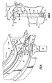
- Figure 2 schematically illustrates a portion of the gas turbine engine 10 that is located between the compressor section 16 and a beginning of the combustion section 18.
- a diffuser 30 is positioned at this location to expand the flow of air having passed through the compressor section 16.
- the diffuser 30 includes an outer casing or housing 32 that has an opening 34 to receive a cold air buffer supply tube 36.
- a radially inner bearing housing 38 Adjacent to the housing 32 is a radially inner bearing housing 38 that defines a bearing compartment 40. Bearings 42 are supported by the bearing housing 38.
- the bearing housing 38 includes an opening 44 (shown in Figure 4 ) that receives the cold air buffer supply tube 36.
- the cold air buffer supply tube 36 directs air into the bearing compartment 40 to cool the bearings 42 and other associated components in this location.
- the cold air buffer supply tube 36 is directly attached to the bearing housing 38 at a threaded attachment interface; however, any other suitable attachment interface could also be used such as a press-fit for example.
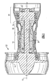
- the cold air buffer supply tube 36 is shown in greater detail in Figure 3 .
- the cold air buffer supply tube 36 includes a tube body 50 defining an internal cavity 49 (shown in Figure 5 ).
- the tube body 40 has a first tube end 52 and a second tube end 54.
- a fitting 56 is attached to the first tube end 52.
- the fitting 56 is attached to the tube body 50 at a first brazed attachment interface 58.
- the fitting 56 is to be connected to an external tube associated with an air supply.
- the fitting 56 can be connected to the external tube via any suitable connection interface.
- a metering cap 60 is attached to the second tube end 54 of the tube body 50.
- the tube body 50 is fabricated from a nickel alloy material and the metering cap 60 and fitting 56 are fabricated from a stainless steel material It should be appreciated by one of ordinary skill in the art that other types of materials could also be used.
- the metering cap 60 includes a plurality of holes 62 that direct flow into the bearing compartment 40 (shown in Figure 4 ).
- the metering cap 60 comprises a cup-shaped body having a solid distal end face 64, an opposite open end face 66, and a peripheral wall 68 that extends from the solid end face 64 to the open end face 66.
- the peripheral wall 68 and the solid end face 64 cooperate to define an internal cavity 70 that is in fluid communication with the tube body 50. Attachment of the metering cap 60 to the tube body 50 will be discussed in detail below.
- the holes 62 are formed in the peripheral wall 68 which surrounds a longitudinal axis A of the tube body 50.
- the holes 62 are circumferentially spaced apart from each other about the central axis A.
- the holes 62 facilitate directing flow from the internal cavity 70 into the bearing compartment 40 when the buffer supply tube 36 is attached to the bearing housing 38.
- the metering cap 60 includes four holes 62 that are generally equally spaced apart from each other about the longitudinal axis A.
- the holes 62 are shaped to provide a desired flow rate into the bearing compartment 40. Although four equally spaced holes are shown, it should be appreciated that other numbers, shapes, and spacing of holes could be formed within the metering cap 60.
- the metering cap 60 also includes an enlarged diameter portion 74 that is formed about the peripheral wall 68.
- the enlarged diameter portion 74 comprises a stop surface that engages the bearing housing 38 to properly position the plurality of holes 62 within the bearing compartment 40.
- a threaded surface 76 is formed on a radially outer surface of the peripheral wall 68, and is positioned axially between the enlarged diameter portion 74 and the holes 62.
- the metering cap 60 is attached to the tube body 50 at a second brazed attachment interface 80.
- the fitting 56 is attached to the tube body 50 at the first brazed attachment interface 58.
- the cold buffer supply tube 36 includes the tube body 50, the metering cap 60, and the fitting 56 assembled to form a single-piece tube assembly that is installable in the gas turbine engine 10 as a unit.
- the bearing housing 38 is positioned at a desired location relative to the diffuser housing 32.
- the cold air buffer supply tube 36 is first installed in the opening 34 by inserting the cold air buffer supply tube 36 in an inward direction into the diffuser housing 32.
- the cold air buffer supply tube 36 is then threaded into direct engagement with the bearing housing 38 at the opening 44. More specifically, the threaded surface 76 is threaded into engagement with the bearing housing 38 until the enlarged diameter portion 74 contacts the bearing housing 38.
- the holes 62 of the metering cap 60 are orientated in a desired position within the bearing compartment 40 such that the flow can be directed to desired locations.
Landscapes
- Engineering & Computer Science (AREA)
- Mechanical Engineering (AREA)
- General Engineering & Computer Science (AREA)
- Chemical & Material Sciences (AREA)
- Combustion & Propulsion (AREA)
- Measuring Volume Flow (AREA)
- Structures Of Non-Positive Displacement Pumps (AREA)
- Magnetic Bearings And Hydrostatic Bearings (AREA)
Applications Claiming Priority (1)
| Application Number | Priority Date | Filing Date | Title |
|---|---|---|---|
| US12/052,768 US8240974B2 (en) | 2008-03-21 | 2008-03-21 | Cold air buffer supply tube |
Publications (3)
| Publication Number | Publication Date |
|---|---|
| EP2103780A2 true EP2103780A2 (fr) | 2009-09-23 |
| EP2103780A3 EP2103780A3 (fr) | 2013-02-13 |
| EP2103780B1 EP2103780B1 (fr) | 2018-05-02 |
Family
ID=40548860
Family Applications (1)
| Application Number | Title | Priority Date | Filing Date |
|---|---|---|---|
| EP09250624.5A Active EP2103780B1 (fr) | 2008-03-21 | 2009-03-04 | Tube d'approvisionnement d'un buffer d'air froid |
Country Status (2)
| Country | Link |
|---|---|
| US (1) | US8240974B2 (fr) |
| EP (1) | EP2103780B1 (fr) |
Cited By (1)
| Publication number | Priority date | Publication date | Assignee | Title |
|---|---|---|---|---|
| EP2880275A4 (fr) * | 2012-07-30 | 2015-08-26 | United Technologies Corp | Système de service de compartiment avant pour une turbine à gaz à architecture à engrenages |
Families Citing this family (13)
| Publication number | Priority date | Publication date | Assignee | Title |
|---|---|---|---|---|
| US8992173B2 (en) * | 2011-11-04 | 2015-03-31 | United Technologies Corporation | Tie-rod nut including a nut flange with a plurality of mounting apertures |
| US20140003920A1 (en) * | 2012-07-02 | 2014-01-02 | United Technologies Corporation | Flow metering anti-rotation outer diameter (od) hex nut |
| US9896968B2 (en) | 2012-07-30 | 2018-02-20 | United Technologies Corporation | Forward compartment baffle arrangement for a geared turbofan engine |
| US20140144121A1 (en) * | 2012-11-28 | 2014-05-29 | Pratt & Whitney Canada Corp. | Gas turbine engine with bearing oil leak recuperation system |
| US9617916B2 (en) | 2012-11-28 | 2017-04-11 | Pratt & Whitney Canada Corp. | Gas turbine engine with bearing buffer air flow and method |
| EP2938859B1 (fr) * | 2012-12-29 | 2019-05-22 | United Technologies Corporation | Architecture de refroidissement destinée à un carter d'échappement de turbine |
| WO2014105522A1 (fr) * | 2012-12-29 | 2014-07-03 | United Technologies Corporation | Mélange de flux d'air dans une cavité à diamètre interne (di) |
| WO2014152123A1 (fr) * | 2013-03-14 | 2014-09-25 | United Technologies Corporation | Joint de dissuasion à écran thermique pour moteur à turbine à gaz |
| US9803501B2 (en) * | 2014-02-14 | 2017-10-31 | United Technologies Corporation | Engine mid-turbine frame distributive coolant flow |
| US10309308B2 (en) * | 2015-01-16 | 2019-06-04 | United Technologies Corporation | Cooling passages for a mid-turbine frame |
| US9988943B2 (en) * | 2015-04-27 | 2018-06-05 | United Technologies Corporation | Fitting for mid-turbine frame of gas turbine engine |
| CN104819016B (zh) * | 2015-05-05 | 2016-09-21 | 中国航空动力机械研究所 | 涡轮后支承轴承座、冷却方法及涡轮风扇发动机 |
| US11352896B2 (en) | 2020-08-21 | 2022-06-07 | Pratt & Whitney Canada Corp. | Tube assembly for a gas turbine engine |
Citations (5)
| Publication number | Priority date | Publication date | Assignee | Title |
|---|---|---|---|---|
| US4156342A (en) | 1976-06-11 | 1979-05-29 | Westinghouse Canada Limited | Cooling apparatus for a bearing in a gas turbine |
| GB2152148A (en) | 1983-12-23 | 1985-07-31 | United Technologies Corp | Controlling bearing chamber temperature in gas turbine engine |
| US4574584A (en) | 1983-12-23 | 1986-03-11 | United Technologies Corporation | Method of operation for a gas turbine engine |
| US4645415A (en) | 1983-12-23 | 1987-02-24 | United Technologies Corporation | Air cooler for providing buffer air to a bearing compartment |
| EP1862639A1 (fr) | 2006-06-01 | 2007-12-05 | Nuovo Pignone S.P.A. | Dispositif pour l'optimisation du refroidissement dans des turbines à gaz |
Family Cites Families (10)
| Publication number | Priority date | Publication date | Assignee | Title |
|---|---|---|---|---|
| US4542623A (en) * | 1983-12-23 | 1985-09-24 | United Technologies Corporation | Air cooler for providing buffer air to a bearing compartment |
| US5526640A (en) * | 1994-05-16 | 1996-06-18 | Technical Directions, Inc. | Gas turbine engine including a bearing support tube cantilevered from a turbine nozzle wall |
| US6102577A (en) * | 1998-10-13 | 2000-08-15 | Pratt & Whitney Canada Corp. | Isolated oil feed |
| US6234746B1 (en) * | 1999-08-04 | 2001-05-22 | General Electric Co. | Apparatus and methods for cooling rotary components in a turbine |
| IT1317538B1 (it) * | 2000-05-15 | 2003-07-09 | Nuovo Pignone Spa | Dispositivo per il controllo dei flussi di refrigerazione delleturbine a gas |
| US6843059B2 (en) * | 2002-11-19 | 2005-01-18 | General Electric Company | Combustor inlet diffuser with boundary layer blowing |
| US6910852B2 (en) * | 2003-09-05 | 2005-06-28 | General Electric Company | Methods and apparatus for cooling gas turbine engine rotor assemblies |
| US7156618B2 (en) * | 2004-11-17 | 2007-01-02 | Pratt & Whitney Canada Corp. | Low cost diffuser assembly for gas turbine engine |
| US7303372B2 (en) * | 2005-11-18 | 2007-12-04 | General Electric Company | Methods and apparatus for cooling combustion turbine engine components |
| US7874158B2 (en) * | 2005-11-29 | 2011-01-25 | United Technologies Corporation | Dirt separator for compressor diffuser in gas turbine engine |
-
2008
- 2008-03-21 US US12/052,768 patent/US8240974B2/en active Active
-
2009
- 2009-03-04 EP EP09250624.5A patent/EP2103780B1/fr active Active
Patent Citations (5)
| Publication number | Priority date | Publication date | Assignee | Title |
|---|---|---|---|---|
| US4156342A (en) | 1976-06-11 | 1979-05-29 | Westinghouse Canada Limited | Cooling apparatus for a bearing in a gas turbine |
| GB2152148A (en) | 1983-12-23 | 1985-07-31 | United Technologies Corp | Controlling bearing chamber temperature in gas turbine engine |
| US4574584A (en) | 1983-12-23 | 1986-03-11 | United Technologies Corporation | Method of operation for a gas turbine engine |
| US4645415A (en) | 1983-12-23 | 1987-02-24 | United Technologies Corporation | Air cooler for providing buffer air to a bearing compartment |
| EP1862639A1 (fr) | 2006-06-01 | 2007-12-05 | Nuovo Pignone S.P.A. | Dispositif pour l'optimisation du refroidissement dans des turbines à gaz |
Cited By (3)
| Publication number | Priority date | Publication date | Assignee | Title |
|---|---|---|---|---|
| EP2880275A4 (fr) * | 2012-07-30 | 2015-08-26 | United Technologies Corp | Système de service de compartiment avant pour une turbine à gaz à architecture à engrenages |
| US9410447B2 (en) | 2012-07-30 | 2016-08-09 | United Technologies Corporation | Forward compartment service system for a geared architecture gas turbine engine |
| EP3543480A1 (fr) * | 2012-07-30 | 2019-09-25 | United Technologies Corporation | Système de servitudes de compartiment avant pour une turbine à gaz à architecture à engrenages |
Also Published As
| Publication number | Publication date |
|---|---|
| US20090238678A1 (en) | 2009-09-24 |
| US8240974B2 (en) | 2012-08-14 |
| EP2103780A3 (fr) | 2013-02-13 |
| EP2103780B1 (fr) | 2018-05-02 |
Similar Documents
| Publication | Publication Date | Title |
|---|---|---|
| US8240974B2 (en) | Cold air buffer supply tube | |
| EP2208933B1 (fr) | Ensemble de chambre de combustion et dôme pour moteur de turbine | |
| US8944749B2 (en) | Oil purge system for a mid turbine frame | |
| US9982600B2 (en) | Pre-skewed capture plate | |
| US10415831B2 (en) | Combustor assembly with mounted auxiliary component | |
| EP2224102A2 (fr) | Refroidissement de l'ensemble virole d'un moteur à turbine à gaz | |
| US9657593B2 (en) | Aircraft gas turbine having a core engine casing with cooling-air tubes | |
| EP3039344B1 (fr) | Interface de montage de coupelle de turbulence pour une chambre de combustion de turbine à gaz | |
| EP2144002A2 (fr) | Manchon avec ouvertures d'air pour le refroidissement d'un conduit de fumées | |
| JP5149596B2 (ja) | 燃焼器ドームミキサー保持手段 | |
| CN107208896A (zh) | 航空器涡轮发动机的喷注系统与燃料喷注喷嘴之间的密封设备 | |
| US20160265375A1 (en) | Piloted retaining plate for a face seal arrangement | |
| CN106545368B (zh) | 陶瓷基质复合物环形护罩固持方法-cmc销头 | |
| US8677765B2 (en) | Gas-turbine combustion chamber with a holding mechanism for a seal for an attachment | |
| EP2900942B1 (fr) | Écran thermique pour carter intermédiaire de turbine | |
| EP2971967B1 (fr) | Tube d'allumage à bouchon inversé | |
| CN110366661B (zh) | 用于燃烧器的端盖组件 | |
| US20140090397A1 (en) | Bleed tube attachment | |
| US11746699B2 (en) | Gas turbine engine | |
| US10030582B2 (en) | Orientation feature for swirler tube | |
| EP4328419B1 (fr) | Ensemble d'échappement pour purger une cavité de nacelle d'un système de propulsion | |
| US20160376925A1 (en) | Seal support structures for turbomachines | |
| JP6563312B2 (ja) | ガスタービンエンジンの抽気構造 |
Legal Events
| Date | Code | Title | Description |
|---|---|---|---|
| PUAI | Public reference made under article 153(3) epc to a published international application that has entered the european phase |
Free format text: ORIGINAL CODE: 0009012 |
|
| AK | Designated contracting states |
Kind code of ref document: A2 Designated state(s): AT BE BG CH CY CZ DE DK EE ES FI FR GB GR HR HU IE IS IT LI LT LU LV MC MK MT NL NO PL PT RO SE SI SK TR |
|
| AX | Request for extension of the european patent |
Extension state: AL BA RS |
|
| PUAL | Search report despatched |
Free format text: ORIGINAL CODE: 0009013 |
|
| AK | Designated contracting states |
Kind code of ref document: A3 Designated state(s): AT BE BG CH CY CZ DE DK EE ES FI FR GB GR HR HU IE IS IT LI LT LU LV MC MK MT NL NO PL PT RO SE SI SK TR |
|
| AX | Request for extension of the european patent |
Extension state: AL BA RS |
|
| RIC1 | Information provided on ipc code assigned before grant |
Ipc: F01D 25/12 20060101ALI20130110BHEP Ipc: F01D 25/16 20060101ALI20130110BHEP Ipc: F02C 7/18 20060101ALI20130110BHEP Ipc: F01D 5/08 20060101AFI20130110BHEP |
|
| 17P | Request for examination filed |
Effective date: 20130813 |
|
| RBV | Designated contracting states (corrected) |
Designated state(s): AT BE BG CH CY CZ DE DK EE ES FI FR GB GR HR HU IE IS IT LI LT LU LV MC MK MT NL NO PL PT RO SE SI SK TR |
|
| AKX | Designation fees paid |
Designated state(s): DE GB |
|
| RAP1 | Party data changed (applicant data changed or rights of an application transferred) |
Owner name: UNITED TECHNOLOGIES CORPORATION |
|
| STAA | Information on the status of an ep patent application or granted ep patent |
Free format text: STATUS: EXAMINATION IS IN PROGRESS |
|
| 17Q | First examination report despatched |
Effective date: 20161130 |
|
| GRAP | Despatch of communication of intention to grant a patent |
Free format text: ORIGINAL CODE: EPIDOSNIGR1 |
|
| STAA | Information on the status of an ep patent application or granted ep patent |
Free format text: STATUS: GRANT OF PATENT IS INTENDED |
|
| INTG | Intention to grant announced |
Effective date: 20170914 |
|
| GRAS | Grant fee paid |
Free format text: ORIGINAL CODE: EPIDOSNIGR3 |
|
| GRAA | (expected) grant |
Free format text: ORIGINAL CODE: 0009210 |
|
| STAA | Information on the status of an ep patent application or granted ep patent |
Free format text: STATUS: THE PATENT HAS BEEN GRANTED |
|
| AK | Designated contracting states |
Kind code of ref document: B1 Designated state(s): DE GB |
|
| REG | Reference to a national code |
Ref country code: GB Ref legal event code: FG4D |
|
| REG | Reference to a national code |
Ref country code: DE Ref legal event code: R096 Ref document number: 602009052069 Country of ref document: DE |
|
| REG | Reference to a national code |
Ref country code: DE Ref legal event code: R097 Ref document number: 602009052069 Country of ref document: DE |
|
| PLBE | No opposition filed within time limit |
Free format text: ORIGINAL CODE: 0009261 |
|
| STAA | Information on the status of an ep patent application or granted ep patent |
Free format text: STATUS: NO OPPOSITION FILED WITHIN TIME LIMIT |
|
| 26N | No opposition filed |
Effective date: 20190205 |
|
| REG | Reference to a national code |
Ref country code: DE Ref legal event code: R081 Ref document number: 602009052069 Country of ref document: DE Owner name: RAYTHEON TECHNOLOGIES CORPORATION (N.D.GES.D.S, US Free format text: FORMER OWNER: UNITED TECHNOLOGIES CORPORATION, FARMINGTON, CONN., US Ref country code: DE Ref legal event code: R081 Ref document number: 602009052069 Country of ref document: DE Owner name: RTX CORPORATION (N.D.GES.D. STAATES DELAWARE),, US Free format text: FORMER OWNER: UNITED TECHNOLOGIES CORPORATION, FARMINGTON, CONN., US |
|
| P01 | Opt-out of the competence of the unified patent court (upc) registered |
Effective date: 20230519 |
|
| REG | Reference to a national code |
Ref country code: DE Ref legal event code: R081 Ref document number: 602009052069 Country of ref document: DE Owner name: RTX CORPORATION (N.D.GES.D. STAATES DELAWARE),, US Free format text: FORMER OWNER: RAYTHEON TECHNOLOGIES CORPORATION (N.D.GES.D.STAATES DELAWARE), ARLINGTON, VA, US |
|
| PGFP | Annual fee paid to national office [announced via postgrant information from national office to epo] |
Ref country code: GB Payment date: 20260219 Year of fee payment: 18 |
|
| PGFP | Annual fee paid to national office [announced via postgrant information from national office to epo] |
Ref country code: DE Payment date: 20260219 Year of fee payment: 18 |