EP2103792A1 - Compresseur d'une turbine à gaz doté d'une dispositif de prélèvement d'air - Google Patents
Compresseur d'une turbine à gaz doté d'une dispositif de prélèvement d'air Download PDFInfo
- Publication number
- EP2103792A1 EP2103792A1 EP09003325A EP09003325A EP2103792A1 EP 2103792 A1 EP2103792 A1 EP 2103792A1 EP 09003325 A EP09003325 A EP 09003325A EP 09003325 A EP09003325 A EP 09003325A EP 2103792 A1 EP2103792 A1 EP 2103792A1
- Authority
- EP
- European Patent Office
- Prior art keywords
- bleed
- circumferential direction
- angle
- boa
- rotor
- Prior art date
- Legal status (The legal status is an assumption and is not a legal conclusion. Google has not performed a legal analysis and makes no representation as to the accuracy of the status listed.)
- Granted
Links
- 238000000605 extraction Methods 0.000 claims abstract description 27
- 238000011144 upstream manufacturing Methods 0.000 claims abstract description 11
- 239000002184 metal Substances 0.000 claims description 9
- 230000002093 peripheral effect Effects 0.000 claims description 5
- 238000005070 sampling Methods 0.000 description 20
- 238000004519 manufacturing process Methods 0.000 description 3
- 238000001816 cooling Methods 0.000 description 2
- 230000003993 interaction Effects 0.000 description 2
- 210000002023 somite Anatomy 0.000 description 2
- 230000001419 dependent effect Effects 0.000 description 1
- 238000009826 distribution Methods 0.000 description 1
- 238000005516 engineering process Methods 0.000 description 1
- 239000000446 fuel Substances 0.000 description 1
- 238000011084 recovery Methods 0.000 description 1
- 238000000926 separation method Methods 0.000 description 1
- 230000006641 stabilisation Effects 0.000 description 1
- 238000011105 stabilization Methods 0.000 description 1
- 230000000087 stabilizing effect Effects 0.000 description 1
- 230000003068 static effect Effects 0.000 description 1
- 230000000638 stimulation Effects 0.000 description 1
- 230000001052 transient effect Effects 0.000 description 1
Images



Classifications
-
- F—MECHANICAL ENGINEERING; LIGHTING; HEATING; WEAPONS; BLASTING
- F02—COMBUSTION ENGINES; HOT-GAS OR COMBUSTION-PRODUCT ENGINE PLANTS
- F02C—GAS-TURBINE PLANTS; AIR INTAKES FOR JET-PROPULSION PLANTS; CONTROLLING FUEL SUPPLY IN AIR-BREATHING JET-PROPULSION PLANTS
- F02C6/00—Plural gas-turbine plants; Combinations of gas-turbine plants with other apparatus; Adaptations of gas-turbine plants for special use
- F02C6/04—Gas-turbine plants providing heated or pressurised working fluid for other apparatus, e.g. without mechanical power output
- F02C6/06—Gas-turbine plants providing heated or pressurised working fluid for other apparatus, e.g. without mechanical power output providing compressed gas
- F02C6/08—Gas-turbine plants providing heated or pressurised working fluid for other apparatus, e.g. without mechanical power output providing compressed gas the gas being bled from the gas-turbine compressor
-
- F—MECHANICAL ENGINEERING; LIGHTING; HEATING; WEAPONS; BLASTING
- F02—COMBUSTION ENGINES; HOT-GAS OR COMBUSTION-PRODUCT ENGINE PLANTS
- F02C—GAS-TURBINE PLANTS; AIR INTAKES FOR JET-PROPULSION PLANTS; CONTROLLING FUEL SUPPLY IN AIR-BREATHING JET-PROPULSION PLANTS
- F02C9/00—Controlling gas-turbine plants; Controlling fuel supply in air- breathing jet-propulsion plants
- F02C9/16—Control of working fluid flow
- F02C9/18—Control of working fluid flow by bleeding, bypassing or acting on variable working fluid interconnections between turbines or compressors or their stages
-
- F—MECHANICAL ENGINEERING; LIGHTING; HEATING; WEAPONS; BLASTING
- F04—POSITIVE - DISPLACEMENT MACHINES FOR LIQUIDS; PUMPS FOR LIQUIDS OR ELASTIC FLUIDS
- F04D—NON-POSITIVE-DISPLACEMENT PUMPS
- F04D29/00—Details, component parts, or accessories
- F04D29/40—Casings; Connections of working fluid
- F04D29/52—Casings; Connections of working fluid for axial pumps
- F04D29/54—Fluid-guiding means, e.g. diffusers
- F04D29/541—Specially adapted for elastic fluid pumps
-
- F—MECHANICAL ENGINEERING; LIGHTING; HEATING; WEAPONS; BLASTING
- F04—POSITIVE - DISPLACEMENT MACHINES FOR LIQUIDS; PUMPS FOR LIQUIDS OR ELASTIC FLUIDS
- F04D—NON-POSITIVE-DISPLACEMENT PUMPS
- F04D29/00—Details, component parts, or accessories
- F04D29/40—Casings; Connections of working fluid
- F04D29/52—Casings; Connections of working fluid for axial pumps
- F04D29/54—Fluid-guiding means, e.g. diffusers
- F04D29/541—Specially adapted for elastic fluid pumps
- F04D29/542—Bladed diffusers
- F04D29/544—Blade shapes
-
- F—MECHANICAL ENGINEERING; LIGHTING; HEATING; WEAPONS; BLASTING
- F04—POSITIVE - DISPLACEMENT MACHINES FOR LIQUIDS; PUMPS FOR LIQUIDS OR ELASTIC FLUIDS
- F04D—NON-POSITIVE-DISPLACEMENT PUMPS
- F04D27/00—Control, e.g. regulation, of pumps, pumping installations or pumping systems specially adapted for elastic fluids
- F04D27/02—Surge control
- F04D27/0207—Surge control by bleeding, bypassing or recycling fluids
- F04D27/023—Details or means for fluid extraction
-
- F—MECHANICAL ENGINEERING; LIGHTING; HEATING; WEAPONS; BLASTING
- F05—INDEXING SCHEMES RELATING TO ENGINES OR PUMPS IN VARIOUS SUBCLASSES OF CLASSES F01-F04
- F05D—INDEXING SCHEME FOR ASPECTS RELATING TO NON-POSITIVE-DISPLACEMENT MACHINES OR ENGINES, GAS-TURBINES OR JET-PROPULSION PLANTS
- F05D2240/00—Components
- F05D2240/10—Stators
- F05D2240/12—Fluid guiding means, e.g. vanes
- F05D2240/122—Fluid guiding means, e.g. vanes related to the trailing edge of a stator vane
-
- Y—GENERAL TAGGING OF NEW TECHNOLOGICAL DEVELOPMENTS; GENERAL TAGGING OF CROSS-SECTIONAL TECHNOLOGIES SPANNING OVER SEVERAL SECTIONS OF THE IPC; TECHNICAL SUBJECTS COVERED BY FORMER USPC CROSS-REFERENCE ART COLLECTIONS [XRACs] AND DIGESTS
- Y02—TECHNOLOGIES OR APPLICATIONS FOR MITIGATION OR ADAPTATION AGAINST CLIMATE CHANGE
- Y02T—CLIMATE CHANGE MITIGATION TECHNOLOGIES RELATED TO TRANSPORTATION
- Y02T50/00—Aeronautics or air transport
- Y02T50/60—Efficient propulsion technologies, e.g. for aircraft
Definitions
- the invention relates to a gas turbine compressor according to the features of the preamble of claim 1.
- the invention relates to a gas turbine compressor from which bleed air is taken in a housing region.
- bleeders In turbomachinery, bleeders (turbo-compressors) are supplied at different positions for the purpose of supplying subsystems or external users, such as the aircraft cabin, for the purpose of stabilizing the compressor during transient maneuvers, for turbine cooling purposes, or for flow recirculation within the compressor taken from the compressor housing ( Fig. 1 ).
- This removal can be done either between two rows of blades or within a row of blades ( Fig. 2 ) or a combination of both.
- the removal geometry can in principle have any conceivable shape.
- the air extraction geometry is either a circumferential slot 7 or a discrete hole 8 or a combination of both on the compressor housing.
- the geometry of the air extraction is very simple and therefore not optimally matched to the flow conditions that prevail at the sampling point near the compressor housing. As a result, the flow can not optimally flow into the bleed air sampling geometry. This leads, for example, to flow separation when the flow enters the extraction geometry and to high pressure loss within the extraction geometry.
- Another problem is an undesirable interaction between the flow in the compressor and the flow in the extraction geometry. This leads, for example, to Flow backflow from the extraction geometry into the main flow. This leads to loss of compressor efficiency, loss of compressor stability, and possibly mechanical stimulation of the compressor blade through to blade failure.
- the invention has for its object to provide a gas turbine compressor of the type mentioned, which has a high efficiency with a simple structure and ease of manufacture.
- a bleed air extraction geometry adapted to the flow conditions prevailing in the compressor at the removal point solves the problems described above.
- the solution according to the invention thus relates to an adapted bleed air extraction geometry for the air extraction between two blade rows (rotor 3 / stator 4 or stator 4 / rotor 3 but also stator 4 / stator 4 or rotor 3 / rotor 3) and in front of or behind a row of blades ( Rotor 3 or stator 4).
- This may be according to the invention to axial or radial compressor in a turbo- or turbomachine.
- the bleed air extraction geometry according to the invention is characterized by minimal pressure loss and maximum efficiency.
- the present invention describes an optimized removal geometry that can be described with the aid of a few geometric and machine-specific parameters.
- the idea on which the invention is based is to design the removal geometry such that the flow can flow without disruption into the removal geometry, which leads to a minimization of the local total pressure loss and is deflected within the removal geometry such that the swirl of the flow occurs Zero is reduced and thereby a maximum of static pressure recovery is achieved.
- the extraction geometry is inclined on the one hand in a defined angle in the circumferential direction to the compressor housing and on the other hand receives a profiling in the axial direction adapted to the direction of the inflowing flow in the extraction geometry.
- This flow direction becomes in the case that before, i. upstream of the sampling point, a stator blade is located, determined from the blade discharge angle, in the event that upstream is a rotor blade, determined from the blade Abströmwinkel and the rotational speed.
- the relevant quantity is the flow direction parallel to the machine axis, i. 0 degrees.
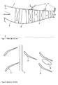
- the Fig. 1 shows a schematic representation in axial section view of a housing 1 and a rotatably mounted hub 2, on which rotor blades 3 are arranged.
- the housing carries in a known manner stator blades 4.
- the machine axis is provided with the reference numeral 5.
- the shows Fig. 1 in a schematic representation bleed air sampling devices 6 or bleed air extraction geometries.
- Fig. 2 again shown in schematic representation, namely as a circumferential slot 7 or as a discrete hole or recesses. 8
- the Fig. 3 shows first illustrations for explaining the invention.
- the upper part of the Fig. 3 shows the definition of the rotor metal angle MW ROTOR , which is defined to a parallel to the machine axis 5 arranged straight lines.
- the lower part of the Fig. 3 shows (also in magnification) a stator blade with pressure side DS and suction side SS and the definition of the angle and angle ranges.
- the Fig. 4 shows in axial view schematically a Axialraums leading edge 14 and an axial direction trailing edge 15 of a bleed air sampling / bleed air extraction geometry 6. Furthermore, further design information, in particular to r G and r N shown.
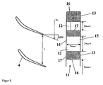
- the Fig. 5 shows a housing view with a viewing direction in the radial direction to the outside, from which can be seen in a strip-shaped peripheral portion 11 recesses 12. These have the aforementioned circumferential direction leading edges 16 and circumferential direction trailing edges 17 and axial direction leading edges 14 and axial direction trailing edges 15. Furthermore, the dimensioning in the X direction and Y direction results, from which the areas of the recesses 12 are calculated.
- the Fig. 6 shows an end view in which the arcuate contours of the hub 2 and a housing surface 18 of the housing 1 are reproduced greatly enlarged. This results in particular in the definition of the entrance angle ⁇ E and the exit angle ⁇ A.
- the Fig. 7 shows an analog representation of Fig. 5 with further angle definitions.
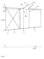
- the Fig. 8 shows an axial side view, from which it is particularly apparent that in the axial direction, the angle at the axial direction leading edge 14 and the axial direction trailing edge 15 may be arbitrary.
- the Fig. 9 shows possible distributions of the arrangements of the bleed air extraction devices 6, these may be arranged uniformly or non-uniformly on the circumference.
- the solution according to the invention advantageously leads to minimize the pressure losses in bleed air sampling geometries and to prevent the negative interaction with the main compressor flow.
- bleed air extraction is more efficient than non-optimized geometry.
- the turbine cooling, the compressor stabilization and the cabin printing can be realized more efficiently.
- This leads to improved compressor flow, improved bleed air flow and thus to improved compressor efficiency, stability and Finally, lower fuel consumption of the engine.
- the improved geometry is easy to manufacture and does not require any additional manufacturing technology costs, it is cost-neutral. In addition, it does not add weight to the compactor module as it replaces existing geometries.
Landscapes
- Engineering & Computer Science (AREA)
- Mechanical Engineering (AREA)
- General Engineering & Computer Science (AREA)
- Chemical & Material Sciences (AREA)
- Combustion & Propulsion (AREA)
- Physics & Mathematics (AREA)
- Fluid Mechanics (AREA)
- Geometry (AREA)
- Structures Of Non-Positive Displacement Pumps (AREA)
Applications Claiming Priority (1)
| Application Number | Priority Date | Filing Date | Title |
|---|---|---|---|
| DE102008014957A DE102008014957A1 (de) | 2008-03-19 | 2008-03-19 | Gasturbinenverdichter mit Zapfluftentnahme |
Publications (2)
| Publication Number | Publication Date |
|---|---|
| EP2103792A1 true EP2103792A1 (fr) | 2009-09-23 |
| EP2103792B1 EP2103792B1 (fr) | 2011-08-24 |
Family
ID=40821615
Family Applications (1)
| Application Number | Title | Priority Date | Filing Date |
|---|---|---|---|
| EP09003325A Active EP2103792B1 (fr) | 2008-03-19 | 2009-03-06 | Compresseur d'une turbine à gaz doté d'une dispositif de prélèvement d'air |
Country Status (3)
| Country | Link |
|---|---|
| US (1) | US8220276B2 (fr) |
| EP (1) | EP2103792B1 (fr) |
| DE (1) | DE102008014957A1 (fr) |
Cited By (2)
| Publication number | Priority date | Publication date | Assignee | Title |
|---|---|---|---|---|
| US9021803B2 (en) | 2011-02-09 | 2015-05-05 | Daimler Ag | Turbine for an exhaust gas turbocharger and exhaust gas turbocharger having such a turbine |
| CN111810453A (zh) * | 2019-04-10 | 2020-10-23 | 三菱重工业株式会社 | 静叶片单元、压缩机及燃气轮机 |
Families Citing this family (17)
| Publication number | Priority date | Publication date | Assignee | Title |
|---|---|---|---|---|
| DE102010002114A1 (de) | 2010-02-18 | 2011-08-18 | Rolls-Royce Deutschland Ltd & Co KG, 15827 | Gasturbine mit einer Zapflufteinrichtung für den Verdichter |
| FR2958694B1 (fr) * | 2010-04-07 | 2014-04-18 | Snecma | Compresseur de moteur, en particulier de turboreacteur d'aeronef, muni d'un systeme de prelevement d'air |
| GB201015029D0 (en) * | 2010-09-10 | 2010-10-20 | Rolls Royce Plc | Gas turbine engine |
| DE102011107523B4 (de) * | 2011-07-15 | 2016-08-11 | MTU Aero Engines AG | System zum Einblasen eines Fluids, Verdichter sowie Turbomaschine |
| US9638201B2 (en) * | 2012-06-20 | 2017-05-02 | United Technologies Corporation | Machined aerodynamic intercompressor bleed ports |
| US9528391B2 (en) | 2012-07-17 | 2016-12-27 | United Technologies Corporation | Gas turbine engine outer case with contoured bleed boss |
| US20140338360A1 (en) * | 2012-09-21 | 2014-11-20 | United Technologies Corporation | Bleed port ribs for turbomachine case |
| DE102013222514A1 (de) | 2013-11-06 | 2015-05-07 | MTU Aero Engines AG | Dichtungsanordnung für eine Strömungsmaschine |
| EP2871368B1 (fr) | 2013-11-12 | 2018-09-12 | MTU Aero Engines GmbH | Compresseur de turbine à gaz |
| US10125781B2 (en) * | 2015-12-30 | 2018-11-13 | General Electric Company | Systems and methods for a compressor diffusion slot |
| US20180119619A1 (en) * | 2016-11-02 | 2018-05-03 | Pratt & Whitney Canada Corp. | Gas turbine engine with bleed slots and method of forming |
| FR3061519B1 (fr) * | 2016-12-30 | 2019-01-25 | Safran Aircraft Engines | Moyeu de carter intermediaire comprenant des canaux de guidage du flux de decharge formes par les ailettes de decharge |
| US20180313364A1 (en) * | 2017-04-27 | 2018-11-01 | General Electric Company | Compressor apparatus with bleed slot including turning vanes |
| US10934943B2 (en) * | 2017-04-27 | 2021-03-02 | General Electric Company | Compressor apparatus with bleed slot and supplemental flange |
| US12146423B2 (en) | 2023-01-11 | 2024-11-19 | General Electric Company | Compressor bleed pressure recovery |
| US12313078B2 (en) | 2023-04-26 | 2025-05-27 | Ge Infrastructure Technology Llc | Extraction impeller for axial compressor |
| US20250052191A1 (en) * | 2023-08-07 | 2025-02-13 | Pratt & Whitney Canada Corp. | Compressor bleed offtake |
Citations (4)
| Publication number | Priority date | Publication date | Assignee | Title |
|---|---|---|---|---|
| US4008977A (en) * | 1975-09-19 | 1977-02-22 | United Technologies Corporation | Compressor bleed system |
| EP0638725A1 (fr) | 1993-08-10 | 1995-02-15 | ABB Management AG | Dispositif pour le soutirage d'air secondaire d'un compresseur axial |
| EP1329615A2 (fr) | 2002-01-17 | 2003-07-23 | United Technologies Corporation | Système de prélèvement d'air de l'étage redressseur d'un compresseur |
| EP1801403A2 (fr) | 2005-12-21 | 2007-06-27 | General Electric Company | Turbosoufflante comprenant un compresseur de suralimentation avec système de décharge compact |
Family Cites Families (12)
| Publication number | Priority date | Publication date | Assignee | Title |
|---|---|---|---|---|
| US4479755A (en) * | 1982-04-22 | 1984-10-30 | A/S Kongsberg Vapenfabrikk | Compressor boundary layer bleeding system |
| US4546605A (en) * | 1983-12-16 | 1985-10-15 | United Technologies Corporation | Heat exchange system |
| US4882902A (en) * | 1986-04-30 | 1989-11-28 | General Electric Company | Turbine cooling air transferring apparatus |
| GB2192229B (en) * | 1986-07-04 | 1990-05-02 | Rolls Royce Plc | A compressor and air bleed system |
| US5059093A (en) * | 1990-06-07 | 1991-10-22 | United Technologies Corporation | Compressor bleed port |
| JPH04132899A (ja) * | 1990-09-25 | 1992-05-07 | Mitsubishi Heavy Ind Ltd | 軸流送風機 |
| US5209633A (en) * | 1990-11-19 | 1993-05-11 | General Electric Company | High pressure compressor flowpath bleed valve extraction slot |
| US6550254B2 (en) * | 2001-08-17 | 2003-04-22 | General Electric Company | Gas turbine engine bleed scoops |
| US20040191058A1 (en) * | 2003-03-31 | 2004-09-30 | Baumann P. William | Compressor bleed |
| DE102004043036A1 (de) * | 2004-09-06 | 2006-03-09 | Rolls-Royce Deutschland Ltd & Co Kg | Strömungsarbeitsmaschine mit Fluidentnahme |
| WO2006091138A1 (fr) * | 2005-02-25 | 2006-08-31 | Volvo Aero Corporation | Structure de purge pour passage de purge dans un moteur a turbine a gaz |
| US20080141677A1 (en) * | 2006-12-15 | 2008-06-19 | Siemens Power Generation, Inc. | Axial tangential radial on-board cooling air injector for a gas turbine |
-
2008
- 2008-03-19 DE DE102008014957A patent/DE102008014957A1/de not_active Withdrawn
-
2009
- 2009-03-06 EP EP09003325A patent/EP2103792B1/fr active Active
- 2009-03-18 US US12/382,571 patent/US8220276B2/en active Active
Patent Citations (4)
| Publication number | Priority date | Publication date | Assignee | Title |
|---|---|---|---|---|
| US4008977A (en) * | 1975-09-19 | 1977-02-22 | United Technologies Corporation | Compressor bleed system |
| EP0638725A1 (fr) | 1993-08-10 | 1995-02-15 | ABB Management AG | Dispositif pour le soutirage d'air secondaire d'un compresseur axial |
| EP1329615A2 (fr) | 2002-01-17 | 2003-07-23 | United Technologies Corporation | Système de prélèvement d'air de l'étage redressseur d'un compresseur |
| EP1801403A2 (fr) | 2005-12-21 | 2007-06-27 | General Electric Company | Turbosoufflante comprenant un compresseur de suralimentation avec système de décharge compact |
Cited By (2)
| Publication number | Priority date | Publication date | Assignee | Title |
|---|---|---|---|---|
| US9021803B2 (en) | 2011-02-09 | 2015-05-05 | Daimler Ag | Turbine for an exhaust gas turbocharger and exhaust gas turbocharger having such a turbine |
| CN111810453A (zh) * | 2019-04-10 | 2020-10-23 | 三菱重工业株式会社 | 静叶片单元、压缩机及燃气轮机 |
Also Published As
| Publication number | Publication date |
|---|---|
| EP2103792B1 (fr) | 2011-08-24 |
| US20090301102A1 (en) | 2009-12-10 |
| US8220276B2 (en) | 2012-07-17 |
| DE102008014957A1 (de) | 2009-09-24 |
Similar Documents
| Publication | Publication Date | Title |
|---|---|---|
| EP2103792B1 (fr) | Compresseur d'une turbine à gaz doté d'une dispositif de prélèvement d'air | |
| EP2003292B1 (fr) | Machine de travail fluidique avec virole d'aube dotée d'un rebord | |
| DE2642603C3 (de) | Einrichtung zur Pumpverhütung bei Axialverdichtern | |
| EP2025945B1 (fr) | Machine de traitement des écoulements dotée d'un creux de paroi de canal de ceinture | |
| EP2362065B1 (fr) | Canal de dérivation avec couronne d'aubes statoriques dans un turboréacteur avec soufflante | |
| EP2275643B1 (fr) | Aube de moteur dotée d'une charge de rebords avant surélevée | |
| DE10233032A1 (de) | Strömungsarbeitsmaschine mit integriertem Fluidzirkulationssystem | |
| DE102008011645A1 (de) | Strömungsarbeitsmaschine mit Rotoren mit niedrigen Rotoraustrittswinkeln | |
| EP2881548B1 (fr) | Compresseur de turbine à gaz | |
| EP1948939B1 (fr) | Roue mobile de compresseur radial | |
| EP2180195A2 (fr) | Turbomachine avec contrôle du jeu des aubes | |
| EP2927503A1 (fr) | Compresseur de turbine à gaz, moteur d'avion et méthode de dimensionnement | |
| EP3078804A1 (fr) | Agencement virole pour une rangée d'aubes de rotor ou stator et turbine associée | |
| DE2853340A1 (de) | Vorrichtung zum erzeugen eines vorwirbels am verdichtereingang eines turbinen-triebwerkes | |
| EP3536974A1 (fr) | Compresseur de turbine à gaz | |
| EP1970542B2 (fr) | Décalage d'aube en fonction d'étranglement dans des turbomachines | |
| DE102019008225B4 (de) | Schaufel für eine rotationsmaschine oder fluidmaschine und damit ausgestattete rotationsmaschine oder fluidmaschine | |
| EP1865148B1 (fr) | Machine de traitement des écoulements dotée de rotors de distribution d'énergie supérieure spécifique | |
| DE102010002395B4 (de) | Turbofantriebwerk mit im Nebenstromkanal angeordneten Leitschaufeln und Stützstreben | |
| DE2822499A1 (de) | Zentrifugalpumpe | |
| EP3032107B1 (fr) | Pompe turbomoleculaire | |
| EP2362079B1 (fr) | Turbine à gaz comprenant un dispositif de prélèvement d'air du compresseur | |
| DE102010044819A1 (de) | Axialturbine und ein Verfahren zum Abführen eines Stroms von einer Axialturbine | |
| DE102004041652B4 (de) | Vermeidung einer Verdichterförderstörung über ausgeprägte Flügelformen | |
| EP3734081A1 (fr) | Dispositif de modification de flux pour compresseurs |
Legal Events
| Date | Code | Title | Description |
|---|---|---|---|
| PUAI | Public reference made under article 153(3) epc to a published international application that has entered the european phase |
Free format text: ORIGINAL CODE: 0009012 |
|
| AK | Designated contracting states |
Kind code of ref document: A1 Designated state(s): AT BE BG CH CY CZ DE DK EE ES FI FR GB GR HR HU IE IS IT LI LT LU LV MC MK MT NL NO PL PT RO SE SI SK TR |
|
| AX | Request for extension of the european patent |
Extension state: AL BA RS |
|
| 17P | Request for examination filed |
Effective date: 20100129 |
|
| 17Q | First examination report despatched |
Effective date: 20100316 |
|
| AKX | Designation fees paid |
Designated state(s): DE FR GB |
|
| GRAP | Despatch of communication of intention to grant a patent |
Free format text: ORIGINAL CODE: EPIDOSNIGR1 |
|
| GRAS | Grant fee paid |
Free format text: ORIGINAL CODE: EPIDOSNIGR3 |
|
| GRAA | (expected) grant |
Free format text: ORIGINAL CODE: 0009210 |
|
| AK | Designated contracting states |
Kind code of ref document: B1 Designated state(s): DE FR GB |
|
| REG | Reference to a national code |
Ref country code: GB Ref legal event code: FG4D Free format text: NOT ENGLISH |
|
| REG | Reference to a national code |
Ref country code: DE Ref legal event code: R096 Ref document number: 502009001151 Country of ref document: DE Effective date: 20111020 |
|
| PLBE | No opposition filed within time limit |
Free format text: ORIGINAL CODE: 0009261 |
|
| STAA | Information on the status of an ep patent application or granted ep patent |
Free format text: STATUS: NO OPPOSITION FILED WITHIN TIME LIMIT |
|
| 26N | No opposition filed |
Effective date: 20120525 |
|
| REG | Reference to a national code |
Ref country code: DE Ref legal event code: R097 Ref document number: 502009001151 Country of ref document: DE Effective date: 20120525 |
|
| REG | Reference to a national code |
Ref country code: FR Ref legal event code: PLFP Year of fee payment: 8 |
|
| REG | Reference to a national code |
Ref country code: FR Ref legal event code: PLFP Year of fee payment: 9 |
|
| REG | Reference to a national code |
Ref country code: FR Ref legal event code: PLFP Year of fee payment: 10 |
|
| PGFP | Annual fee paid to national office [announced via postgrant information from national office to epo] |
Ref country code: GB Payment date: 20200327 Year of fee payment: 12 |
|
| GBPC | Gb: european patent ceased through non-payment of renewal fee |
Effective date: 20210306 |
|
| PG25 | Lapsed in a contracting state [announced via postgrant information from national office to epo] |
Ref country code: GB Free format text: LAPSE BECAUSE OF NON-PAYMENT OF DUE FEES Effective date: 20210306 |
|
| P01 | Opt-out of the competence of the unified patent court (upc) registered |
Effective date: 20230528 |
|
| PGFP | Annual fee paid to national office [announced via postgrant information from national office to epo] |
Ref country code: DE Payment date: 20250327 Year of fee payment: 17 |
|
| PGFP | Annual fee paid to national office [announced via postgrant information from national office to epo] |
Ref country code: FR Payment date: 20250324 Year of fee payment: 17 |