EP2103814A2 - Actionneur rotatif fluidique - Google Patents
Actionneur rotatif fluidique Download PDFInfo
- Publication number
- EP2103814A2 EP2103814A2 EP20090003165 EP09003165A EP2103814A2 EP 2103814 A2 EP2103814 A2 EP 2103814A2 EP 20090003165 EP20090003165 EP 20090003165 EP 09003165 A EP09003165 A EP 09003165A EP 2103814 A2 EP2103814 A2 EP 2103814A2
- Authority
- EP
- European Patent Office
- Prior art keywords
- housing
- rotary drive
- drive according
- intermediate body
- fluid
- Prior art date
- Legal status (The legal status is an assumption and is not a legal conclusion. Google has not performed a legal analysis and makes no representation as to the accuracy of the status listed.)
- Granted
Links
Images


Classifications
-
- F—MECHANICAL ENGINEERING; LIGHTING; HEATING; WEAPONS; BLASTING
- F15—FLUID-PRESSURE ACTUATORS; HYDRAULICS OR PNEUMATICS IN GENERAL
- F15B—SYSTEMS ACTING BY MEANS OF FLUIDS IN GENERAL; FLUID-PRESSURE ACTUATORS, e.g. SERVOMOTORS; DETAILS OF FLUID-PRESSURE SYSTEMS, NOT OTHERWISE PROVIDED FOR
- F15B15/00—Fluid-actuated devices for displacing a member from one position to another; Gearing associated therewith
- F15B15/08—Characterised by the construction of the motor unit
- F15B15/12—Characterised by the construction of the motor unit of the oscillating-vane or curved-cylinder type
Definitions
- the invention relates to a fluid-actuated rotary drive, comprising a housing which is composed of at least three housing bodies arranged in the axial direction of a main axis in the form of two end bodies and at least one intermediate body arranged therebetween, wherein immediately adjacent housing bodies each jointly define a housing chamber, in which one about the main axis rotatably mounted rotary piston, so that staggered in the axial direction of the main axis at least two each housed in a separate housing chamber rotary piston are present, all rotary pistons with one and the same outside of the housing the tapping of a torque enabling output shaft are in rotary drive connection and wherein each swivel piston receiving it Housing chamber divided into two working spaces, which controlled to generate the torque via running in the housing wall internal fluid channels controlled by an Antr iebsfluid are acted upon.
- One from the DE 93 20 601 U1 known rotary drive of this type includes a plurality of axially staggered housed in a housing pivot piston, which are driven by fluid respectively to a reciprocating rotary motion and which are drivingly coupled via an overrunning clutch to an output shaft, at the outside of the housing a torque can be tapped.
- the oscillating pistons can be driven in the same direction both in opposite directions and in order to produce a higher torque.
- the drive fluid is supplied and discharged via formed in the two end bodies of the housing fluid channels, which communicate with externally formed on the two end bodies connecting ports in combination, which are available in duplicate for each a swivel piston receiving housing chamber.
- connection openings realized channel systems can be connected in particular by means of pressure medium lines, in order to supply and remove the drive fluid controlled.
- a rotary drive in principle comparable structure discloses the DE 44 06 376 A1 in which, however, only one of two pivot pistons is used for driving purposes, while the other pivot piston is part of a fluidic braking device.
- a hydraulic swing motor which has three annular spaces, in each of which a pivot piston is arranged.
- the fluid feed into the middle annular space takes place bypassing an outer annular space axially through a plurality of housing parts.
- the two outer annular spaces are supplied with fluid from the middle annulus through channels formed in the central pivot piston.
- the work spaces of all the housing chambers which are responsible for generating rectified torque portions when fluid is applied are connected via the internal fluid channels together with one of two connection openings formed on the outer surface of the one, first end body, wherein the connection openings each have their own first fluid channel portion are connected to one of the working spaces of the first end body limited by the first housing chamber and wherein the working spaces of each immediately adjacent housing chambers by means of interposed intermediate body passing through the second fluid channel sections are interconnected.
- two or more rotary pistons are housed in separate housing chambers and can be applied simultaneously in the same direction with drive fluid, so that a high torque and therefore with very compact dimensions, a high line density can be achieved.
- the user only has to connect two connection openings to the external fluid supply, since the allocation of the right fluid distribution to the individual working chambers in the housing interior is accomplished via the corresponding internal course of fluid channels.
- the two connection openings are formed together on the one, first end body and connected via the internal first fluid channel sections to only the housing chamber bounded by the first end body.
- the subsequent housing chamber does not communicate directly connected to the connection openings, but is connected to the first housing chamber assignment correct, via second fluid channel sections which extend in which the adjacent housing chambers from each other dividing intermediate body.
- each further housing chamber is connected via corresponding second fluid channel sections of its associated intermediate body to the respective upstream housing chamber.
- connection openings for the various drive chambers are expediently arranged on a side surface of the first connection body oriented at right angles to the main axis.
- This side surface is designed in particular circular cylindrical.
- connection openings of the Abgriffsabites are relatively widely spaced and are easily accessible even when installed on-site rotary drive to perform the desired connection measures.
- All rotary pistons expediently contain a provided for storage on the output shaft bearing bush, from radially projecting a wing portion, which can be acted upon by the drive fluid and thereby driven to pivot about the main axis.
- the preferably rotationally fixed in both directions of rotation connection between the bearing bush and the output shaft is advantageously realized via splined profiles, one of which is present on the inner circumference of the bearing bushes and on the outer circumference of the output shaft. There is the advantageous possibility sansstecken the bushings of all rotary pistons on one and the same splined profile of the output shaft, which greatly simplifies the assembly.
- second fluid channel sections are expediently formed directly in that wall portion of the intermediate body, which acts as an axial boundary between the adjacent housing chambers.
- This is in particular a plate-shaped intermediate wall with a right angle to the main axis, around which is arranged coaxially an annular outer wall of the intermediate body, which protrudes axially on both sides over the intermediate wall to form the desired housing chamber in cooperation with the respective subsequent housing body.
- the housing chambers may be circular in shape, with the major axis as the center.
- For interlocking fixation on the intermediate body of the intermediate body is advantageously penetrated by an axial opening into which the partition wall elements of both adjacent Housing chambers can engage from opposite sides.
- the first closing body is expediently equipped with a first mechanical interface and the second closing body with a second mechanical interface, wherein each intermediate body at one end face a third mechanical interface complementary to the first mechanical interface and at the other end face Complementary fourth mechanical interface to the second mechanical interface.
- the output shaft can then be driven to oscillate about its longitudinal axis coinciding with the main axis.
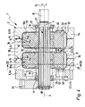
- the generally designated by reference numeral 1 rotary drive includes a compact, substantially block-shaped housing 2, in which a plurality of rotationally driven by Fluidbeetzleyung rotatable rotary piston 3a, 3b are arranged with a rotatably mounted in the housing 2 about its axially extending main axis 4 output shaft 5 in Rotary drive connection stand on the outside of the housing 2, a torque can be tapped. Operates the rotary drive 1 in particular with compressed air, although an operation with a hydraulic medium is possible.
- the housing 2 is composed of several in the axial direction of the main axis 4 juxtaposed housing bodies 6, which are summarized by zugankerartig acting fastening screws 7 to form an assembly.
- the housing 2 contains three housing bodies 6, namely a first end body 6a arranged on the one end side, a second end body 6b arranged on the opposite end side and an intermediate body 6c arranged between these two end bodies 6a, 6b.
- a plurality of intermediate bodies 6c could be incorporated axially in succession.
- the end face of the first end body 6a facing the intermediate body 6c is designed as a first mechanical interface 12, which is connected to the third mechanical end formed by the facing end face of the intermediate body 6c Interface 14 matches.
- a second mechanical interface 13 is formed on the end face of the second end body 6b facing the intermediate body 6c, which mates with a fourth mechanical interface 15 located on the end face of the intermediate body 6c opposite the third mechanical interface 14.
- the mutually facing mechanical interfaces 12, 14; 13, 15 are complementary to each other and engage axially into each other, causing a mutual centering in the radial direction with respect to the main axis 4. As a result, an exact Koaxiallage is guaranteed.
- the first mechanical interface 12 preferably has first centering means 12a in the form of an annular axial depression concentric with the main axis 4, in which complementarily formed third centering means 14a engage the third mechanical interface 14, here in the form of an annular axial projection concentric with the main axis 4 are formed.
- the second mechanical interface 13 is provided with second centering means 13a of the same type as the third centering means 14a and engaged with fourth centering means 15a of the fourth mechanical interface 15, which are of the same type as the first centering means 12a.
- the cooperating interfaces 12, 14; 13, 15 formed complementary to each other. It is also advantageous if the first mechanical interface 12 is identical to the fourth mechanical interface 15 and if, furthermore, the second mechanical interface 13 is identical to the third mechanical interface 14. In this way, it is possible between the two end bodies 6a, 6b a integrate any number of intermediate bodies 6c in axial succession, wherein all the housing body 6 via complementary mechanical interfaces with their adjacent housing bodies 6 are engaged. If there are a plurality of intermediate bodies 6c, it is expedient to fall back on intermediate bodies 6 of identical construction.
- mutually adjacent housing bodies 6 in the axial direction of the main axis 4 each jointly delimit a housing chamber, of which the housing chamber bounded by the first end body 6a is designated as the first housing chamber 16a and the housing chamber bounded by the second end body 6b is referred to as the second housing chamber 16b.
- the attached to each other housing body 6 each contain a recess, said recesses come to lie in pairs so that each a housing chamber 16a, 16b is formed.
- the two housing chambers 16a, 16b are expediently identical. You have how to look FIG. 3 can be seen, expediently a circular outline.
- the already mentioned output shaft 5 passes through the housing 2 in the longitudinal direction and is rotatably mounted on the two end bodies 6a, 6b via a respective bearing device 17 with respect to the housing 2.
- Each housing body has a central opening 18 through which the output shaft 5 engages.
- Each housing chamber 16a, 16b is divided in the circumferential direction into a first working space 22 and a second working space 23. The subdivision is carried out by a radial distance from the main axis 4 in the housing chamber 16a, 16b stationary inserted partition element 24 and the already mentioned pivoting piston 3a, 3b.
- the pivoting piston 3a, 3b includes a bearing bush 25 which is penetrated by the output shaft 5 and protrudes from the radially a wing portion 26.
- the entire, the housing 2 traversing the longitudinal section of the output shaft 5 is provided on the outer circumference with an outer splined profile 27, which passes through the bearing bushes 25 all of the pivoting pistons 3 a, 3 b and in this case with one on the inner circumference of the relevant bearing bush 25 formed complementary inner splined profile 28 positively engages stands. In this way results in a rotationally fixed in both directions of rotation connection between each pivot piston 3a, 3b and the output shaft. 5
- the rotary piston 3a, 3b is provided on its outer surface with at least one seal 32 which slidably bears against the inner surface of the associated housing chamber 16a, 16b.
- the seated on the cylindrical periphery of the bearing bush 25 portion of the seal 32 is in sealing contact with the partition wall member 24, the outside also carries at least one seal 33, via which it sealingly also on the inner surface associated housing chamber 16a, 16b abuts.
- pivoting piston 3a, 3b and the associated partition wall element 24 form a total of a drawn into the housing chamber 16a, 16b partition, through which the two aforementioned working spaces 22, 23 are fluid-tight separated from each other.
- each housing chamber 16a, 16b are controlled acted upon by a drive fluid, which consequently also the wing portion 26 of the contained Pivoting piston 3a, 3b acted upon and causes due to the pressure difference prevailing in the two working chambers 22, 23, that the pivot piston 3a, 3b performs a rotational movement 34 indicated by a double arrow with the main axis 4 as a rotation axis.
- the wing portion 26 pivots about the main axis 4 in or counterclockwise, with the result that the volumes of the two working chambers 22, 23 change.
- the achievable by alternating fluid loading of the two working chambers 22, 23 oscillating rotational movement can be tapped outside of the housing 2 acting as Abgriffsabrough 35 longitudinal portion of the output shaft 5 for driving a not further shown component.
- the tapping portion 35 projects out of the housing 2 on the side of the second end body 6b.
- the two end positions of the rotary movement 34 are predetermined either by the partition wall element 24 or by an optional rotation angle adjusting device 36, which is arranged in particular outside of the housing 2.
- a rotational angle adjusting device 36 is present and includes a pivot stop 37 which is non-rotatably attached to a rear end portion 38 of the output shaft 5, which protrudes axially from the housing 2 in the region of the first connection body 6a, opposite to the Abgriffsabites 35.
- a retaining ring 42 is attached to the housing 2, under the participation of at least one not shown stop body is fixed to the housing, which projects into the pivoting of a radially projecting stop wing 43 of the pivot stop 37 to specify the desired tilt angle.
- a first connection opening 45 and a second connection opening 46 are formed on the outer surface 44 of the first end body 6a. They can each be connected to a control valve means leading to a not further shown, and in particular designed as a fluid hose fluid line to feed or remove as desired a drive fluid.
- the fluid admission of all the housing chambers 16, 17 is controlled jointly via these two connection openings 45, 46, so that no further connection openings are required.
- connection openings 45, 46 are located on the first connection body 6a, since it is relatively far away from the tapping section 35 and thus the connection openings 45, 46 are optimally accessible for connection measures, even if the rotary drive 1 is at the place of use is installed.
- a fluid admission of the respectively first working chamber 22 of the two housing chambers 16a, 16b causes the associated pivoting piston 3a, 3b is fluidly applied in a manner that it experiences a torque in a clockwise direction.
- a fluid admission of the second working space 23 causes a torque counterclockwise.
- the respective other work spaces are relieved of pressure by appropriate operation of said control valve means.
- first connection opening 45 communicates with all the first working spaces 22 at the same time.
- a fluidic connection is interposed via an internal second fluid channel 48 the second port 46 and all second working spaces 23 before.
- the channel profile of the internal fluid channels 47, 48 has an advantageous effect on a flexible stringing together of any number of housing bodies 6, without having to take special measures with regard to the fluidic connection during assembly of the housing body 6.
- Both internal fluid channels 47, 48 each contain a first fluid channel section 47a, 48a which, starting from the associated connection opening 45, 46, passes through the wall of the first end body 6a and opens into the first housing chamber 16a.
- the first fluid channel section 47a communicates with the first working chamber 22, the other first fluid channel section 48a with the second working chamber 23.
- the pressure supply and pressure relief of the second housing chamber 16b does not take place directly via the two connection openings 45, 46, but indirectly through the first housing chamber 16a.
- the intermediate body 6c is penetrated by two second fluid channel sections 47b, 48b, one of which establishes a connection between the two adjoining first working spaces 22 and the other of which establishes a connection between the two adjoining second working spaces 23.
- Any additional housing chamber would be connected in a comparable manner to the respective upstream housing chamber, namely via second fluid channel sections, which then enforce the then additionally incorporated intermediate body.
- connection openings 45, 46 In the second end body 16b no fluid channels are required. However, it would certainly be possible to attach the connection openings 45, 46 alternatively to the second end body 6b. Furthermore, it would be possible to form on the second end body 6b also two connection openings 45, 46, which communicate with the associated housing chamber via a first fluid channel section, so that the user has the option of either the one on the first end body 6a or on the second End body 6 b existing connection openings 45, 46 to use and to close the unused connection openings 45, 46.
- connection openings 45, 46 are arranged on a lateral outer surface 44 of the first end body 6a oriented at right angles to the main axis 4.
- the first end body 6a is preferably contoured circular-cylindrical, which is especially true for the outer contour of the at least one intermediate body 6c.
- the second closing body 6b has an outer contour projecting at least partially over the adjoining intermediate body 6c, in particular square or rectangular, so that a plurality of corner regions outside the outer contour of the intermediate body 6c can be used, for example by means of fastening the rotary drive 1 to a supporting structure Mounting holes 52.
- the two end bodies 6a, 6b are expediently designed in the shape of a decal and contain one of the openings 18 interspersed on the side of the end wall 53, which adjoins the outer circumference of an intermediate body 6c outwardly projecting annular wall portion 54.
- the intermediate body 6c expediently has a central plate 55, which is penetrated centrally by the associated opening 18 and is preferably plate-shaped, to which a coaxial, annular outer wall 56 of the intermediate body 6c adjoins radially outward, projecting axially over the intermediate wall 55 on both sides.
- the second fluid channel sections 47b, 48b expediently pass through the intermediate body 6c exclusively in the region of the intermediate wall 55, in particular in the immediate vicinity on both sides of the dividing wall element 24. In this way, very short channel connections can be realized and no channels are required in the annular outer wall 56.
- the intermediate wall 55 is expediently traversed by an axial opening 57 in addition to the two second fluid channel sections 47b, 48b, in particular in the region lying between the two second fluid channel sections 47b, 48b.
- the two partition wall elements 24 are anchored in a form-fitting manner from opposite axial sides by engaging with at least one anchoring projection 58 a little way into this axial opening 57.
- each partition element 24 expediently has at least one further anchoring projection 62 which engages in a complementary anchoring recess 63 on the inner surface of the end wall 53.
- the partition wall element 24 arranged in this housing chamber engages in the axial openings 57 of both adjacent intermediate bodies 6c.
- each partition member 58 engages sealingly into the associated axial opening 57 or sealingly abuts the axial opening 57 around the wall of the intermediate body 6c, a fluid transfer between axially adjacent housing chambers 16a, 16b is reliably prevented.
- the opening 18 of the intermediate body 6c is sealed by the fact that the at least one seal 32 of the rotary piston 3a, 3b abuts axially around the aperture 18 with sealing contact on the intermediate wall 55.
- a comparable seal takes place around the opening 18 with respect to the end wall 53 of the end bodies 6a, 6b.
- the rotary drive 1 of the embodiment includes two drive stages.
- the number can be arbitrarily increased by an additional body 6c and a pivot piston is incorporated per further drive stage, in conjunction with the use of another output shaft 5 with a correspondingly extended splined section section.
- Each intermediate body 6c is preferably formed in one piece. The same applies expediently also for each of the two end bodies 6a, 6b.
Landscapes
- Engineering & Computer Science (AREA)
- Physics & Mathematics (AREA)
- Fluid Mechanics (AREA)
- Mechanical Engineering (AREA)
- General Engineering & Computer Science (AREA)
- Hydraulic Motors (AREA)
Applications Claiming Priority (1)
| Application Number | Priority Date | Filing Date | Title |
|---|---|---|---|
| DE200820003944 DE202008003944U1 (de) | 2008-03-20 | 2008-03-20 | Fluidbetätigter Drehantrieb |
Publications (3)
| Publication Number | Publication Date |
|---|---|
| EP2103814A2 true EP2103814A2 (fr) | 2009-09-23 |
| EP2103814A3 EP2103814A3 (fr) | 2013-01-02 |
| EP2103814B1 EP2103814B1 (fr) | 2015-07-08 |
Family
ID=39478106
Family Applications (1)
| Application Number | Title | Priority Date | Filing Date |
|---|---|---|---|
| EP09003165.9A Active EP2103814B1 (fr) | 2008-03-20 | 2009-03-05 | Actionneur rotatif fluidique |
Country Status (2)
| Country | Link |
|---|---|
| EP (1) | EP2103814B1 (fr) |
| DE (1) | DE202008003944U1 (fr) |
Cited By (3)
| Publication number | Priority date | Publication date | Assignee | Title |
|---|---|---|---|---|
| EP2420682A1 (fr) * | 2010-08-21 | 2012-02-22 | FESTO AG & Co. KG | Dispositif d'entraînement rotatif hydraulique |
| CN108005845A (zh) * | 2017-11-08 | 2018-05-08 | 中国航空工业集团公司金城南京机电液压工程研究中心 | 一种同轴径向安装的液压旋转作动装置 |
| CN113635344A (zh) * | 2021-09-10 | 2021-11-12 | 贵州群建精密机械有限公司 | 一种流体驱动关节机构及其使用方法 |
Families Citing this family (5)
| Publication number | Priority date | Publication date | Assignee | Title |
|---|---|---|---|---|
| IT1398128B1 (it) * | 2009-03-27 | 2013-02-14 | Rovel S R L | Attuatore azionato da un fluido in pressione |
| DE102018205637A1 (de) | 2018-04-13 | 2019-10-17 | Festo Ag & Co. Kg | Drehantriebsvorrichtung und damit ausgestatteter Roboterarm eines Roboters |
| DE102018205640B4 (de) | 2018-04-13 | 2020-01-02 | Festo Ag & Co. Kg | Drehantriebsvorrichtung und damit ausgestatteter Roboterarm eines Roboters |
| DE102018205638B4 (de) | 2018-04-13 | 2024-06-13 | Festo Se & Co. Kg | Drehantriebsvorrichtung und damit ausgestatteter Roboterarm eines Roboters |
| GB201818074D0 (en) * | 2018-11-06 | 2018-12-19 | Rolls Royce Plc | Actuator |
Citations (3)
| Publication number | Priority date | Publication date | Assignee | Title |
|---|---|---|---|---|
| DE3942775A1 (de) | 1989-12-23 | 1991-06-27 | Karl Henninger Fa | Hydraulischer schwenkmotor |
| DE9320601U1 (de) | 1993-06-05 | 1994-10-13 | Festo Kg, 73734 Esslingen | Fluidisch betätigbarer Drehantrieb |
| DE4406376A1 (de) | 1994-02-26 | 1995-08-31 | Festo Kg | Fluidisch betätigbarer Drehantrieb |
Family Cites Families (3)
| Publication number | Priority date | Publication date | Assignee | Title |
|---|---|---|---|---|
| DE1503343A1 (de) * | 1966-12-06 | 1970-07-02 | Hausherr & Soehne Rudolf | OElmotor |
| FR1533413A (fr) * | 1967-06-08 | 1968-07-19 | Moteur à fluide sous pression à mouvement rotatif limité | |
| DE1750352A1 (de) * | 1968-04-24 | 1971-01-21 | Hermann Steinbach | Ein- oder Mehrkammer-Drehkolbenzylinder |
-
2008
- 2008-03-20 DE DE200820003944 patent/DE202008003944U1/de not_active Expired - Lifetime
-
2009
- 2009-03-05 EP EP09003165.9A patent/EP2103814B1/fr active Active
Patent Citations (3)
| Publication number | Priority date | Publication date | Assignee | Title |
|---|---|---|---|---|
| DE3942775A1 (de) | 1989-12-23 | 1991-06-27 | Karl Henninger Fa | Hydraulischer schwenkmotor |
| DE9320601U1 (de) | 1993-06-05 | 1994-10-13 | Festo Kg, 73734 Esslingen | Fluidisch betätigbarer Drehantrieb |
| DE4406376A1 (de) | 1994-02-26 | 1995-08-31 | Festo Kg | Fluidisch betätigbarer Drehantrieb |
Cited By (3)
| Publication number | Priority date | Publication date | Assignee | Title |
|---|---|---|---|---|
| EP2420682A1 (fr) * | 2010-08-21 | 2012-02-22 | FESTO AG & Co. KG | Dispositif d'entraînement rotatif hydraulique |
| CN108005845A (zh) * | 2017-11-08 | 2018-05-08 | 中国航空工业集团公司金城南京机电液压工程研究中心 | 一种同轴径向安装的液压旋转作动装置 |
| CN113635344A (zh) * | 2021-09-10 | 2021-11-12 | 贵州群建精密机械有限公司 | 一种流体驱动关节机构及其使用方法 |
Also Published As
| Publication number | Publication date |
|---|---|
| DE202008003944U1 (de) | 2008-06-05 |
| EP2103814A3 (fr) | 2013-01-02 |
| EP2103814B1 (fr) | 2015-07-08 |
Similar Documents
| Publication | Publication Date | Title |
|---|---|---|
| EP2103814B1 (fr) | Actionneur rotatif fluidique | |
| DE102009041119B4 (de) | Oszilliervorrichtung mit doppelter Zahnstange und Ritzel | |
| EP3455467A1 (fr) | Vanne hydraulique pour déphaseur à moteur oscillant d'un arbre à cames | |
| EP2614260B1 (fr) | Dispositif d'entraînement rotatif actionné par un fluide | |
| EP2558755A1 (fr) | Ensemble de vannes | |
| EP2226537B1 (fr) | Clapet anti-retour et unité de soupape en étant équipée | |
| EP1920888B1 (fr) | Outil rotatif à chocs et plaque antérieure pour celui ci | |
| EP0669469B1 (fr) | Actionneur fluidique rotatif | |
| DE2904111A1 (de) | Hydrostatische lenkeinrichtung | |
| DE2906183C2 (de) | Hydrostatische Lenkeinrichtung für Kraftfahrzeuge | |
| DE2852852B1 (de) | Kolbenpumpe,insbesondere Radialkolbenpumpe | |
| DE19942544C2 (de) | Hydraulische Lenkeinrichtung mit Übersetzungsänderung | |
| DE7932853U1 (de) | Umlaufender spannzylinder mit spannkolben fuer spanneinrichtungen an werkzeugmaschinen | |
| CH509535A (de) | Sicherheitsventil für druckmittelbetriebene Vorrichtungen | |
| EP3234374B1 (fr) | Dispositif à air comprimé avec des joints permettant différentes connections fluidiques | |
| DE3741261A1 (de) | Schwenkantrieb mit rueckstelleinheit | |
| DE2917435A1 (de) | Steuerdrehschiebereinrichtung | |
| DE4420694C2 (de) | Dosierpumpe | |
| DE3526319C2 (fr) | ||
| DE102009015976B4 (de) | Ventil mit drehbarem Ventilglied | |
| DE19909918A1 (de) | Vorsteuerbares Wegeventil | |
| DE19828465C2 (de) | Schwenkantrieb für Armaturen | |
| DE2917298A1 (de) | Steuerdrehschiebereinrichtung | |
| DE19626192B4 (de) | Steuereinrichtung zur Steuerung eines hydrostatischen Servoantriebs | |
| DE1814792C3 (de) | Parallel- und innenachsige Rotationskolbenmaschine |
Legal Events
| Date | Code | Title | Description |
|---|---|---|---|
| PUAI | Public reference made under article 153(3) epc to a published international application that has entered the european phase |
Free format text: ORIGINAL CODE: 0009012 |
|
| AK | Designated contracting states |
Kind code of ref document: A2 Designated state(s): AT BE BG CH CY CZ DE DK EE ES FI FR GB GR HR HU IE IS IT LI LT LU LV MC MK MT NL NO PL PT RO SE SI SK TR |
|
| AX | Request for extension of the european patent |
Extension state: AL BA RS |
|
| PUAL | Search report despatched |
Free format text: ORIGINAL CODE: 0009013 |
|
| AK | Designated contracting states |
Kind code of ref document: A3 Designated state(s): AT BE BG CH CY CZ DE DK EE ES FI FR GB GR HR HU IE IS IT LI LT LU LV MC MK MT NL NO PL PT RO SE SI SK TR |
|
| AX | Request for extension of the european patent |
Extension state: AL BA RS |
|
| RIC1 | Information provided on ipc code assigned before grant |
Ipc: F15B 15/12 20060101AFI20121126BHEP |
|
| 17P | Request for examination filed |
Effective date: 20130131 |
|
| AKX | Designation fees paid |
Designated state(s): AT BE BG CH CY CZ DE DK EE ES FI FR GB GR HR HU IE IS IT LI LT LU LV MC MK MT NL NO PL PT RO SE SI SK TR |
|
| GRAP | Despatch of communication of intention to grant a patent |
Free format text: ORIGINAL CODE: EPIDOSNIGR1 |
|
| INTG | Intention to grant announced |
Effective date: 20150220 |
|
| GRAS | Grant fee paid |
Free format text: ORIGINAL CODE: EPIDOSNIGR3 |
|
| GRAA | (expected) grant |
Free format text: ORIGINAL CODE: 0009210 |
|
| AK | Designated contracting states |
Kind code of ref document: B1 Designated state(s): AT BE BG CH CY CZ DE DK EE ES FI FR GB GR HR HU IE IS IT LI LT LU LV MC MK MT NL NO PL PT RO SE SI SK TR |
|
| REG | Reference to a national code |
Ref country code: GB Ref legal event code: FG4D Free format text: NOT ENGLISH |
|
| REG | Reference to a national code |
Ref country code: AT Ref legal event code: REF Ref document number: 735645 Country of ref document: AT Kind code of ref document: T Effective date: 20150715 Ref country code: CH Ref legal event code: EP |
|
| REG | Reference to a national code |
Ref country code: IE Ref legal event code: FG4D Free format text: LANGUAGE OF EP DOCUMENT: GERMAN |
|
| REG | Reference to a national code |
Ref country code: DE Ref legal event code: R096 Ref document number: 502009011202 Country of ref document: DE |
|
| REG | Reference to a national code |
Ref country code: NL Ref legal event code: MP Effective date: 20150708 |
|
| REG | Reference to a national code |
Ref country code: LT Ref legal event code: MG4D |
|
| PG25 | Lapsed in a contracting state [announced via postgrant information from national office to epo] |
Ref country code: LT Free format text: LAPSE BECAUSE OF FAILURE TO SUBMIT A TRANSLATION OF THE DESCRIPTION OR TO PAY THE FEE WITHIN THE PRESCRIBED TIME-LIMIT Effective date: 20150708 Ref country code: NO Free format text: LAPSE BECAUSE OF FAILURE TO SUBMIT A TRANSLATION OF THE DESCRIPTION OR TO PAY THE FEE WITHIN THE PRESCRIBED TIME-LIMIT Effective date: 20151008 Ref country code: LV Free format text: LAPSE BECAUSE OF FAILURE TO SUBMIT A TRANSLATION OF THE DESCRIPTION OR TO PAY THE FEE WITHIN THE PRESCRIBED TIME-LIMIT Effective date: 20150708 Ref country code: FI Free format text: LAPSE BECAUSE OF FAILURE TO SUBMIT A TRANSLATION OF THE DESCRIPTION OR TO PAY THE FEE WITHIN THE PRESCRIBED TIME-LIMIT Effective date: 20150708 Ref country code: GR Free format text: LAPSE BECAUSE OF FAILURE TO SUBMIT A TRANSLATION OF THE DESCRIPTION OR TO PAY THE FEE WITHIN THE PRESCRIBED TIME-LIMIT Effective date: 20151009 |
|
| PG25 | Lapsed in a contracting state [announced via postgrant information from national office to epo] |
Ref country code: ES Free format text: LAPSE BECAUSE OF FAILURE TO SUBMIT A TRANSLATION OF THE DESCRIPTION OR TO PAY THE FEE WITHIN THE PRESCRIBED TIME-LIMIT Effective date: 20150708 Ref country code: IS Free format text: LAPSE BECAUSE OF FAILURE TO SUBMIT A TRANSLATION OF THE DESCRIPTION OR TO PAY THE FEE WITHIN THE PRESCRIBED TIME-LIMIT Effective date: 20151108 Ref country code: HR Free format text: LAPSE BECAUSE OF FAILURE TO SUBMIT A TRANSLATION OF THE DESCRIPTION OR TO PAY THE FEE WITHIN THE PRESCRIBED TIME-LIMIT Effective date: 20150708 Ref country code: PT Free format text: LAPSE BECAUSE OF FAILURE TO SUBMIT A TRANSLATION OF THE DESCRIPTION OR TO PAY THE FEE WITHIN THE PRESCRIBED TIME-LIMIT Effective date: 20151109 Ref country code: SE Free format text: LAPSE BECAUSE OF FAILURE TO SUBMIT A TRANSLATION OF THE DESCRIPTION OR TO PAY THE FEE WITHIN THE PRESCRIBED TIME-LIMIT Effective date: 20150708 Ref country code: PL Free format text: LAPSE BECAUSE OF FAILURE TO SUBMIT A TRANSLATION OF THE DESCRIPTION OR TO PAY THE FEE WITHIN THE PRESCRIBED TIME-LIMIT Effective date: 20150708 |
|
| REG | Reference to a national code |
Ref country code: FR Ref legal event code: PLFP Year of fee payment: 8 |
|
| REG | Reference to a national code |
Ref country code: DE Ref legal event code: R097 Ref document number: 502009011202 Country of ref document: DE |
|
| PG25 | Lapsed in a contracting state [announced via postgrant information from national office to epo] |
Ref country code: DK Free format text: LAPSE BECAUSE OF FAILURE TO SUBMIT A TRANSLATION OF THE DESCRIPTION OR TO PAY THE FEE WITHIN THE PRESCRIBED TIME-LIMIT Effective date: 20150708 Ref country code: SK Free format text: LAPSE BECAUSE OF FAILURE TO SUBMIT A TRANSLATION OF THE DESCRIPTION OR TO PAY THE FEE WITHIN THE PRESCRIBED TIME-LIMIT Effective date: 20150708 Ref country code: EE Free format text: LAPSE BECAUSE OF FAILURE TO SUBMIT A TRANSLATION OF THE DESCRIPTION OR TO PAY THE FEE WITHIN THE PRESCRIBED TIME-LIMIT Effective date: 20150708 Ref country code: CZ Free format text: LAPSE BECAUSE OF FAILURE TO SUBMIT A TRANSLATION OF THE DESCRIPTION OR TO PAY THE FEE WITHIN THE PRESCRIBED TIME-LIMIT Effective date: 20150708 |
|
| PLBE | No opposition filed within time limit |
Free format text: ORIGINAL CODE: 0009261 |
|
| STAA | Information on the status of an ep patent application or granted ep patent |
Free format text: STATUS: NO OPPOSITION FILED WITHIN TIME LIMIT |
|
| PG25 | Lapsed in a contracting state [announced via postgrant information from national office to epo] |
Ref country code: RO Free format text: LAPSE BECAUSE OF FAILURE TO SUBMIT A TRANSLATION OF THE DESCRIPTION OR TO PAY THE FEE WITHIN THE PRESCRIBED TIME-LIMIT Effective date: 20150708 |
|
| 26N | No opposition filed |
Effective date: 20160411 |
|
| PG25 | Lapsed in a contracting state [announced via postgrant information from national office to epo] |
Ref country code: SI Free format text: LAPSE BECAUSE OF FAILURE TO SUBMIT A TRANSLATION OF THE DESCRIPTION OR TO PAY THE FEE WITHIN THE PRESCRIBED TIME-LIMIT Effective date: 20150708 Ref country code: BE Free format text: LAPSE BECAUSE OF NON-PAYMENT OF DUE FEES Effective date: 20160331 |
|
| PG25 | Lapsed in a contracting state [announced via postgrant information from national office to epo] |
Ref country code: LU Free format text: LAPSE BECAUSE OF FAILURE TO SUBMIT A TRANSLATION OF THE DESCRIPTION OR TO PAY THE FEE WITHIN THE PRESCRIBED TIME-LIMIT Effective date: 20160305 Ref country code: MC Free format text: LAPSE BECAUSE OF FAILURE TO SUBMIT A TRANSLATION OF THE DESCRIPTION OR TO PAY THE FEE WITHIN THE PRESCRIBED TIME-LIMIT Effective date: 20150708 |
|
| REG | Reference to a national code |
Ref country code: CH Ref legal event code: PL |
|
| REG | Reference to a national code |
Ref country code: IE Ref legal event code: MM4A |
|
| PG25 | Lapsed in a contracting state [announced via postgrant information from national office to epo] |
Ref country code: LI Free format text: LAPSE BECAUSE OF NON-PAYMENT OF DUE FEES Effective date: 20160331 Ref country code: CH Free format text: LAPSE BECAUSE OF NON-PAYMENT OF DUE FEES Effective date: 20160331 Ref country code: IE Free format text: LAPSE BECAUSE OF NON-PAYMENT OF DUE FEES Effective date: 20160305 |
|
| REG | Reference to a national code |
Ref country code: FR Ref legal event code: PLFP Year of fee payment: 9 |
|
| PGFP | Annual fee paid to national office [announced via postgrant information from national office to epo] |
Ref country code: FR Payment date: 20170323 Year of fee payment: 9 |
|
| REG | Reference to a national code |
Ref country code: AT Ref legal event code: MM01 Ref document number: 735645 Country of ref document: AT Kind code of ref document: T Effective date: 20160305 |
|
| PGFP | Annual fee paid to national office [announced via postgrant information from national office to epo] |
Ref country code: GB Payment date: 20170216 Year of fee payment: 9 |
|
| PG25 | Lapsed in a contracting state [announced via postgrant information from national office to epo] |
Ref country code: NL Free format text: LAPSE BECAUSE OF FAILURE TO SUBMIT A TRANSLATION OF THE DESCRIPTION OR TO PAY THE FEE WITHIN THE PRESCRIBED TIME-LIMIT Effective date: 20150708 |
|
| PG25 | Lapsed in a contracting state [announced via postgrant information from national office to epo] |
Ref country code: AT Free format text: LAPSE BECAUSE OF NON-PAYMENT OF DUE FEES Effective date: 20160305 Ref country code: MT Free format text: LAPSE BECAUSE OF FAILURE TO SUBMIT A TRANSLATION OF THE DESCRIPTION OR TO PAY THE FEE WITHIN THE PRESCRIBED TIME-LIMIT Effective date: 20150708 |
|
| PGFP | Annual fee paid to national office [announced via postgrant information from national office to epo] |
Ref country code: IT Payment date: 20170323 Year of fee payment: 9 |
|
| PG25 | Lapsed in a contracting state [announced via postgrant information from national office to epo] |
Ref country code: HU Free format text: LAPSE BECAUSE OF FAILURE TO SUBMIT A TRANSLATION OF THE DESCRIPTION OR TO PAY THE FEE WITHIN THE PRESCRIBED TIME-LIMIT; INVALID AB INITIO Effective date: 20090305 Ref country code: CY Free format text: LAPSE BECAUSE OF FAILURE TO SUBMIT A TRANSLATION OF THE DESCRIPTION OR TO PAY THE FEE WITHIN THE PRESCRIBED TIME-LIMIT Effective date: 20150708 |
|
| PG25 | Lapsed in a contracting state [announced via postgrant information from national office to epo] |
Ref country code: MK Free format text: LAPSE BECAUSE OF FAILURE TO SUBMIT A TRANSLATION OF THE DESCRIPTION OR TO PAY THE FEE WITHIN THE PRESCRIBED TIME-LIMIT Effective date: 20150708 Ref country code: TR Free format text: LAPSE BECAUSE OF FAILURE TO SUBMIT A TRANSLATION OF THE DESCRIPTION OR TO PAY THE FEE WITHIN THE PRESCRIBED TIME-LIMIT Effective date: 20150708 |
|
| PG25 | Lapsed in a contracting state [announced via postgrant information from national office to epo] |
Ref country code: BG Free format text: LAPSE BECAUSE OF FAILURE TO SUBMIT A TRANSLATION OF THE DESCRIPTION OR TO PAY THE FEE WITHIN THE PRESCRIBED TIME-LIMIT Effective date: 20150708 |
|
| GBPC | Gb: european patent ceased through non-payment of renewal fee |
Effective date: 20180305 |
|
| PG25 | Lapsed in a contracting state [announced via postgrant information from national office to epo] |
Ref country code: GB Free format text: LAPSE BECAUSE OF NON-PAYMENT OF DUE FEES Effective date: 20180305 Ref country code: IT Free format text: LAPSE BECAUSE OF NON-PAYMENT OF DUE FEES Effective date: 20180305 |
|
| PG25 | Lapsed in a contracting state [announced via postgrant information from national office to epo] |
Ref country code: FR Free format text: LAPSE BECAUSE OF NON-PAYMENT OF DUE FEES Effective date: 20180331 |
|
| REG | Reference to a national code |
Ref country code: DE Ref legal event code: R082 Ref document number: 502009011202 Country of ref document: DE Representative=s name: PATENTANWAELTE MAGENBAUER & KOLLEGEN PARTNERSC, DE Ref country code: DE Ref legal event code: R081 Ref document number: 502009011202 Country of ref document: DE Owner name: FESTO SE & CO. KG, DE Free format text: FORMER OWNER: FESTO AG & CO. KG, 73734 ESSLINGEN, DE Ref country code: DE Ref legal event code: R081 Ref document number: 502009011202 Country of ref document: DE Owner name: FESTO AG & CO. KG, DE Free format text: FORMER OWNER: FESTO AG & CO. KG, 73734 ESSLINGEN, DE |
|
| PGFP | Annual fee paid to national office [announced via postgrant information from national office to epo] |
Ref country code: DE Payment date: 20260325 Year of fee payment: 18 |