EP2103834B1 - Dämpfungsventil für einen hydraulischen Schwingungsdämpfer - Google Patents
Dämpfungsventil für einen hydraulischen Schwingungsdämpfer Download PDFInfo
- Publication number
- EP2103834B1 EP2103834B1 EP20090004008 EP09004008A EP2103834B1 EP 2103834 B1 EP2103834 B1 EP 2103834B1 EP 20090004008 EP20090004008 EP 20090004008 EP 09004008 A EP09004008 A EP 09004008A EP 2103834 B1 EP2103834 B1 EP 2103834B1
- Authority
- EP
- European Patent Office
- Prior art keywords
- valve
- openings
- guide body
- damping
- flow
- Prior art date
- Legal status (The legal status is an assumption and is not a legal conclusion. Google has not performed a legal analysis and makes no representation as to the accuracy of the status listed.)
- Active
Links
Images


Classifications
-
- F—MECHANICAL ENGINEERING; LIGHTING; HEATING; WEAPONS; BLASTING
- F16—ENGINEERING ELEMENTS AND UNITS; GENERAL MEASURES FOR PRODUCING AND MAINTAINING EFFECTIVE FUNCTIONING OF MACHINES OR INSTALLATIONS; THERMAL INSULATION IN GENERAL
- F16F—SPRINGS; SHOCK-ABSORBERS; MEANS FOR DAMPING VIBRATION
- F16F9/00—Springs, vibration-dampers, shock-absorbers, or similarly-constructed movement-dampers using a fluid or the equivalent as damping medium
- F16F9/32—Details
- F16F9/44—Means on or in the damper for manual or non-automatic adjustment; such means combined with temperature correction
- F16F9/46—Means on or in the damper for manual or non-automatic adjustment; such means combined with temperature correction allowing control from a distance, i.e. location of means for control input being remote from site of valves, e.g. on damper external wall
- F16F9/466—Throttling control, i.e. regulation of flow passage geometry
-
- F—MECHANICAL ENGINEERING; LIGHTING; HEATING; WEAPONS; BLASTING
- F16—ENGINEERING ELEMENTS AND UNITS; GENERAL MEASURES FOR PRODUCING AND MAINTAINING EFFECTIVE FUNCTIONING OF MACHINES OR INSTALLATIONS; THERMAL INSULATION IN GENERAL
- F16F—SPRINGS; SHOCK-ABSORBERS; MEANS FOR DAMPING VIBRATION
- F16F2230/00—Purpose; Design features
- F16F2230/36—Holes, slots or the like
-
- Y—GENERAL TAGGING OF NEW TECHNOLOGICAL DEVELOPMENTS; GENERAL TAGGING OF CROSS-SECTIONAL TECHNOLOGIES SPANNING OVER SEVERAL SECTIONS OF THE IPC; TECHNICAL SUBJECTS COVERED BY FORMER USPC CROSS-REFERENCE ART COLLECTIONS [XRACs] AND DIGESTS
- Y10—TECHNICAL SUBJECTS COVERED BY FORMER USPC
- Y10T—TECHNICAL SUBJECTS COVERED BY FORMER US CLASSIFICATION
- Y10T137/00—Fluid handling
- Y10T137/8593—Systems
- Y10T137/87917—Flow path with serial valves and/or closures
- Y10T137/88054—Direct response normally closed valve limits direction of flow
Definitions
- the invention relates to a damping valve for a hydraulic vibration damper with an axially movable lock slider having a shaft and a hollow cylindrical valve body, an electromagnetic linear drive for the axial adjustment of the adjusting slide, a stationary arranged guide body, which is designed as a hollow body and having a pin-shaped end, and an annular support body between stationary parts of the linear drive and the guide body, wherein the hollow cylindrical valve body is guided on the journal-shaped end of the guide body and interacts with arranged in the shell of the guide body valve openings such that the free cross-section of the valve openings by an axial movement of the valve body is variable, and wherein the guide body and the support body define an annular flow space, in which open the valve openings of the guide body and arranged in the jacket of the support body flow openings.
- the damping valve can be arranged in a housing which has a flow inlet and a flow outlet and can be fastened as a so-called "backpack valve" on the outside of a hydraulic vibration damper.
- the flow inlet and outlet of the housing is hydraulically connected to fluid chambers of the vibration damper.
- EP 1 538 366 A1 A damping valve with the features described above is made EP 1 538 366 A1 known.
- the support body surrounds the lock slider and is spaced from the lock slider. In this way arises between the lock slider and the support body, an annular space which can be referred to as the outflow chamber in the usually practiced flow direction.
- EP 1 538 366 A1 is described that the annulus is necessary in order to influence the flow of the damping fluid and thus the damping force of the damping valve targeted.
- the flow of the damping fluid can be influenced so that a flow fraction leaves the annular flow space immediately through the outflow, while the remaining flow component deflected in the chamber and is directed to the end face of the lock slider. It is stated that the deflected flow component in the annular space is necessary to compensate for disturbing forces.
- the document gives the expert the additional stimulus to influence the flow resistance in the shell of the guide body through the contour of the valve openings.
- the damping force curve when using the known damping valve is still unsatisfactory. This applies to both the flow-dependent damping force curves and the repeatability.
- the invention has for its object to improve the damping force behavior of the damping valve.
- valve openings of the guide body have a heart-shaped contour, which terminates in the closing direction of the control slide in a tip and starting from the top symmetrically to a symmetry axis predetermined by the tip in each case merges into an arc in a flat rising edge of a wide opening and that the flow openings are respectively directed to the axis of symmetry of a valve opening of the guide body.
- the invention is based on the surprising finding that a flow deflection in the annular flow space between the guide body and the support body is to be avoided and a better flow behavior of the damping valve can be realized when the valve openings and the valve openings associated flow openings of the support body are aligned and when the damping fluid flows through the annular flow space substantially radially without any deflection. It turns out to be advantageous if contrary to the prevailing doctrine of flow pressure loss essentially only occurs at the boundary of the valve openings and pressure losses that occur in the flow through the annular space and in the outflow through the flow openings, on the other hand are negligibly small, in each Functional position of the control slide.
- the flow-through openings in the annular support body are preferably formed as bores.
- the shank of the adjusting slide expediently has at least one pressure compensation bore in a known manner, which hydraulically connects the fluid space within the hollow cylindrical valve body to a fluid space on the rear end face of the shank.
- an opening is arranged in the cylinder wall of the valve body, which in each functional position of the adjusting slide the fluid space within the valve body with the annular flow space between the support body and the Hydraulic valve body connects.
- a further advantageous embodiment of the damping valve according to the invention provides that in the guide body, a passive damping element is used, which can only be flowed through in one direction.
- the passive damping element can be fastened to a cover provided with inflow openings, which can be fastened to the guide body.
- the design of the bearing and guide of the axially movable control slide also affects the accuracy with which the lock slider can be repeatedly adjusted and positioned under the same conditions.
- An embodiment of the invention that is advantageous in this respect provides that the support body is fixed without play to mating surfaces of the guide body and has a cylindrical extension at its end remote from the fixation point, which surrounds the shaft and extends into the region of the linear drive, wherein the cylindrical extension an annular bearing point is arranged, which surrounds the shaft with a small clearance, which allows axial sliding movements of the control valve.
- the bearing point and the shaft slidably guided in the bearing point are preferably designed with a tight clearance fit, while for the fixation of the annular support body on the guide body a transition or interference fit is advantageous.
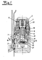
- Damping valve 1 shown is arranged in a housing 2, which has an inlet opening 3 and an outlet opening 4 for connection to a hydraulic vibration damper.
- the design of the housing is arbitrary.
- Fig. 1 1 For the basic structure of the in Fig. 1 1 includes an axially movable locking slide 5, which is preferably formed in one piece and a shaft 6 and a hollow cylindrical valve body 7, an electromagnetic linear actuator 8 for axial adjustment of the control slide 5, a stationary arranged guide body 9, which is designed as a hollow body and a
- the hollow cylindrical valve body is guided on the pin-shaped end 10 of the guide body 9 and cooperates with arranged in the mantle of the guide body 9 valve openings 12 such that the free cross section of the valve openings 12 by an axial movement of the adjusting slide 5 is variable.
- the guide body 9 and the supporting body 11 surrounding it define an annular flow space 13, in FIG the valve openings 12 of the guide body 9 and arranged in the shell of the support body 11 flow openings 14 open.
- valve openings 12 of the guide body 9 have a heart-shaped contour, which terminates in the closing direction of the adjusting slide in a tip 15 and starting from the tip 15 symmetrically to a predetermined by the tip 15 symmetry axis 16 in an arc in a flat rising boundary 17 passes over to a wide opening.
- the flat rising edge 17 may be curved linear or arcuate.
- the through-flow openings 14 are respectively directed to the axis of symmetry 16 of a valve opening 12 of the guide body 9.
- the flow cross-section of the flow-through openings 14 is expediently larger than the free cross-section of the respective associated valve openings 12. Furthermore, the illustrations show that the flow-through openings 14 are formed as bores.
- the shaft 6 of the adjusting slide 5 has at least one pressure compensation bore 18, which hydraulically connects the fluid space within the hollow cylindrical valve body 7 with a fluid space at the rear end face of the shaft 6.
- at least one opening 19 is arranged, which connects the fluid space within the valve body 7 with the annular flow space 13 between the support body and the guide body hydraulically in each functional position of the adjusting slide 5.
- the wall thickness of the valve body tapers towards the end face of the valve body to form a front-side sealing surface.
- the sealing surface is preferably a flat annular surface, which may have a width of, for example, 0.1 mm.
- a passive damping element 20 is used in the embodiment, which can only be flowed through in one direction. Usually, first the flow through the passive damping element 20 and then the flow through the provided in the guide body 9 and in the support body 11 openings. However, another flow direction should not be excluded.
- the damping element 20 is arranged on a lid 21 provided with inflow openings, which can be fastened to the guide body 9.
- the support body 11 is fixed without play in the exemplary embodiment of mating surfaces of the guide body 9 and has at its end remote from the fixation point on a cylindrical extension which surrounds the shaft 6 of the control slide and extends into the region of the linear drive 8.
- a cylindrical extension which surrounds the shaft 6 of the control slide and extends into the region of the linear drive 8.
- annular bearing 22 is arranged, which surrounds the shaft 6 with a small clearance, which allows axial sliding movements of the control valve.
- two damping valves 1 are arranged in a common housing 2 ', which has an inlet opening 3 and an outlet 4.
- a flow guide member 23 is provided, which separates two hydraulic chambers of the housing from each other, that the flowing into the first hydraulic chamber at a retraction movement of the piston rod damping fluid is supplied to the first damping valve in the valve flow direction and in an extension movement of the piston rod in the second Hydraulic space inflowing damping fluid is supplied to the second damping valve in the valve flow direction.
Landscapes
- Engineering & Computer Science (AREA)
- General Engineering & Computer Science (AREA)
- Mechanical Engineering (AREA)
- Details Of Valves (AREA)
- Fluid-Damping Devices (AREA)
- Magnetically Actuated Valves (AREA)
Description
- Die Erfindung betrifft ein Dämpfungsventil für einen hydraulischen Schwingungsdämpfer mit
einem axial beweglichen Stellschieber, der einen Schaft und einen hohlzylindrischen Ventilkörper aufweist,
einem elektromagnetischen Linearantrieb zur axialen Verstellung des Stellschiebers,
einem ortsfest angeordneten Führungskörper, der als Hohlkörper ausgebildet ist und ein zapfenförmiges Ende aufweist, und
einem ringförmigen Stützkörper zwischen ortsfesten Teilen des Linearantriebs und dem Führungskörper,
wobei der hohlzylindrische Ventilkörper auf dem zapfenförmigen Ende des Führungskörpers geführt ist und mit im Mantel des Führungskörpers angeordneten Ventilöffnungen derart zusammenwirkt, dass der freie Querschnitt der Ventilöffnungen durch eine Axialbewegung des Ventilkörpers veränderbar ist, und wobei der Führungskörper und der Stützkörper einen ringförmigen Strömungsraum begrenzen, in den die Ventilöffnungen des Führungskörpers sowie im Mantel des Stützkörpers angeordnete Durchströmöffnungen münden. Das Dämpfungsventil kann in einem Gehäuse angeordnet werden, das einen Strömungseinlass sowie einen Strömungsauslass aufweist und als sogenanntes "Rucksackventil" an der Außenseite eines hydraulischen Schwingungsdämpfers befestigbar ist. Der Strömungseinlass und -auslass des Gehäuses ist hydraulisch an Fluidräume des Schwingungsdämpfers angeschlossen. Durch Betätigung des Stellschiebers ist die Dämpfungskraft des hydraulischen Schwingungsdämpfers stufenlos veränderbar. Werden einem Schwingungsdämpfer zwei Dämpfungsventile zugeordnet, so ist es möglich, die Dämpfungskräfte in der Zugstufe und der Druckstufe des Schwingungsdämpfers unabhängig voneinander beliebig zu verändern. - Ein Dämpfungsventil mit den eingangs beschriebenen Merkmalen ist aus
EP 1 538 366 A1 bekannt. Der Stützkörper umgibt den Stellschieber und ist vom Stellschieber beabstandet angeordnet. Auf diese Weise entsteht zwischen dem Stellschieber und dem Stützkörper ein Ringraum, der bei der zumeist praktizierten Strömungsrichtung auch als Abströmkammer bezeichnet werden kann. InEP 1 538 366 A1 wird beschrieben, dass der Ringraum notwendig ist um die Strömung der Dämpfungsflüssigkeit und damit auch die Dämpfungskraft des Dämpfungsventils gezielt beeinflussen zu können. Durch die Höhe und Breite des ringförmigen Strömungsraums sowie durch die Größe und Anzahl der im Mantel des Stützkörpers angeordneten Durchströmöffnungen kann die Strömung der Dämpfungsflüssigkeit so beeinflusst werden, dass ein Strömungsanteil den ringförmigen Strömungsraum sofort durch die Abströmöffnungen verlässt, während der restliche Strömungsanteil in der Kammer umgelenkt und auf die Stimfläche des Stellschiebers geleitet wird. Es wird ausgeführt, dass der umgelenkte Strömungsanteil im Ringraum zur Kompensation von Störkräften, notwendig. Allgemein gibt die Druckschrift dem Fachmann die zusätzliche Anregung, die Strömungswiderstände im Mantel des Führungskörpers durch die Kontur der Ventilöffnungen zu beeinflussen. Trotz der nach der herrschenden Lehre einzuhaltenden Parameter ist der Dämpfungskraftverlauf bei Verwendung des bekannten Dämpfungsventils noch nicht befriedigend. Das betrifft sowohl die strömungsabhängigen Dämpfungskraftverläufe als auch die Wiederholgenauigkeit. - Der Erfindung liegt die Aufgabe zugrunde, das Dämpfungskraftverhalten des Dämpfungsventils zu verbessern.
- Ausgehend von einem Dämpfungsventil mit den eingangs beschriebenen Merkmalen wird die Aufgabe erfindungsgemäß dadurch gelöst, dass die Ventilöffnungen des Führungskörpers eine herzförmige Kontur aufweisen, die in Schließrichtung des Stellschiebers in einer Spitze ausläuft und ausgehend von der Spitze symmetrisch zu einer durch die Spitze vorgegebenen Symmetrieachse jeweils in einem Bogen in eine flach ansteigenden Berandung einer breiten Öffnung übergeht und dass die Durchströmöffnungen jeweils auf die Symmetrieachse einer Ventilöffnung des Führungskörpers gerichtet sind. Die Erfindung beruht auf der überraschenden Erkenntnis, dass eine Strömungsumlenkung in dem ringförmigen Strömungsraum zwischen dem Führungskörper und dem Stützkörper zu vermeiden ist und ein besseres Strömungsverhalten des Dämpfungsventils realisiert werden kann, wenn die Ventilöffnungen sowie die den Ventilöffnungen zugeordneten Durchströmöffnungen des Stützkörpers fluchten und wenn das Dämpfungsfluid ohne jede Umlenkung den ringförmigen Strömungsraum im Wesentlichen radial durchströmt. Es erweist sich als günstig, wenn entgegen der herrschenden Lehrmeinung der Strömungsdruckverlust im Wesentlichen nur an der Berandung der Ventilöffnungen auftritt und Druckverluste, die bei der Durchströmung des ringförmigen Raumes sowie bei der Abströmung durch die Durchströmöffnungen auftreten, demgegenüber vernachlässigbar klein sind, und zwar in jeder Funktionsstellung des Stellschiebers. Die Durchströmöffnungen in dem ringförmigen Stützkörper sind vorzugsweise als Bohrungen ausgebildet.
- Der Schaft des Stellschiebers weist in an sich bekannter Weise zweckmäßig mindestens eine Druckausgleichsbohrung auf, welche den Fluidraum innerhalb des hohlzylindrischen Ventilkörpers mit einem Fluidraum an der rückseitigen Stimfläche des Schaftes hydraulisch verbindet. Erfindungsgemäß ist in der Zylinderwand des Ventilkörpers eine Öffnung angeordnet, welche in jeder Funktionsstellung des Stellschiebers den Fluidraum innerhalb des Ventilkörpers mit dem ringförmigen Strömungsraum zwischen dem Stützkörper und dem Ventilkörper hydraulisch verbindet. Damit der Ventilkörper ungeachtet der die Ventilöffnungen durchströmenden Dämpfungsfluid mit geringer Kraft präzisionsgenau verstellt werden kann, erweist es sich als vorteilhaft, wenn die Wandstärke des Ventilkörpers sich zur Stimfläche des Ventilkörpers hin unter Ausbildung einer stirnseitigen Dichtfläche verjüngt. Die Dichtfläche kann als beispielsweise 0,1 mm breite ebene Ringfläche ausgebildet sein.
- Eine weitere vorteilhafte Ausgestaltung des erfindungsgemäßen Dämpfungsventils sieht vor, dass in den Führungskörper ein passives Dämpfungselement eingesetzt ist, welches nur in einer Richtung durchströmbar ist. Das passive Dämpfungselement kann an einem mit Einströmöffnungen versehenen Deckel befestigt werden, der an dem Führungsköper befestigbar ist.
- Die Ausgestaltung der Lagerung und Führung des axial beweglichen Stellschiebers wirkt sich ebenfalls auf die Genauigkeit aus, mit der der Stellschieber unter gleichen Bedingungen wiederholt verstellt und positioniert werden kann. Eine in dieser Hinsicht vorteilhafte Ausführung der Erfindung sieht vor, dass der Stützkörper an Passflächen des Führungskörpers spielfrei fixiert ist und an seinem von der Fixierungsstelle abgewandten Ende einen zylindrischen Fortsatz aufweist, der den Schaft umgibt und sich bis in den Bereich des Linearantriebs erstreckt, wobei an dem zylindrischen Fortsatz eine ringförmige Lagerstelle angeordnet ist, die den Schaft mit einem geringen Spiel, welches axiale Gleitbewegungen des Stellventils zulässt, umgibt. Die Lagerstelle und der in der Lagerstelle gleitbeweglich geführte Schaft sind vorzugsweise mit einer engen Spielpassung ausgeführt, während für die Fixierung des ringförmigen Stützkörpers an dem Führungskörper eine Übergangs- oder Presspassung vorteilhaft ist.
- Im Folgenden wird die Erfindung anhand von Ausführungsbeispielen erläutert. Es zeigen schematisch:
- Fig. 1
- einen Längsschnitt durch ein Dämpfungsventil für einen hydraulischen Schwingungsdämpfer,
- Fig. 2
- die Form der in einem ringförmigen Stützkörper vorgesehenen Durchströmöffnungen in einer gegenüber der
Fig. 1 stark vergrößerten, perspektivischen Darstellung, - Fig.3
- eine Anordnung mit zwei Dämpfungsventilen, die in einem gemeinsamen Gehäuse angeordnet sind und eingesetzt werden kann, um die Dämpfungskräfte in der Zugstufe und der Druckstufe eines Schwingungsdämpfers unabhängig voneinander zu verändern.
- Das in
Fig. 1 dargestellte Dämpfungsventil 1 ist in einem Gehäuse 2 angeordnet, welches eine Einlassöffnung 3 sowie eine Auslassöffnung 4 zum Anschluss an einen hydraulischen Schwingungsdämpfer aufweist. Die Gestaltung des Gehäuses ist beliebig. - Zum grundsätzlichen Aufbau des in
Fig. 1 dargestellten Dämpfungsventils 1 gehören ein axial beweglicher Stellschieber 5, der vorzugsweise einteilig ausgebildet ist und einen Schaft 6 sowie einen hohlzylindrischen Ventilkörper 7 aufweist, ein elektromagnetischer Linearantrieb 8 zur axialen Verstellung des Stellschiebers 5, ein ortsfest angeordneter Führungskörper 9, der als Hohlkörper ausgebildet ist und ein zapfenförmiges Ende 10 aufweist, sowie ein ringförmiger Stützkörper 11 zwischen ortsfesten Teilen des Linearantriebs 8 und dem Führungskörper 9. Der hohlzylindrische Ventilkörper ist auf dem zapfenförmigen Ende 10 des Führungskörpers 9 geführt und wirkt mit im Mantel des Führungskörpers 9 angeordneten Ventilöffnungen 12 dergestalt zusammen, dass der freie Querschnitt der Ventilöffnungen 12 durch eine Axialbewegung des Stellschiebers 5 veränderbar ist. Der Führungskörper 9 und der ihn umgebende Stützkörper 11 begrenzen einen ringförmigen Strömungsraum 13, in den die Ventilöffnungen 12 des Führungskörpers 9 sowie im Mantel des Stützkörpers 11 angeordnete Durchströmöffnungen 14 münden. Aus einer vergleichenden Betrachtung derFig. 1 und2 wird deutlich, dass die Ventilöffnungen 12 des Führungskörpers 9 eine herzförmige Kontur aufweisen, die in Schließrichtung des Stellschiebers in einer Spitze 15 ausläuft und ausgehend von der Spitze 15 symmetrisch zu einer durch die Spitze 15 vorgegebenen Symmetrieachse 16 jeweils in einem Bogen in eine flach ansteigende Berandung 17 einer breiten Öffnung übergeht. Die flach ansteigende Berandung 17 kann linear oder bogenförmig gekrümmt sein. Erfindungswesentlich ist ferner, dass die Durchströmöffnungen 14 jeweils auf die Symmetrieachse 16 einer Ventilöffnung 12 des Führungskörpers 9 gerichtet sind. - Der Strömungsquerschnitt der Durchströmöffnungen 14 ist zweckmäßig größer als der freie Querschnitt der jeweils zugeordneten Ventilöffnungen 12. Ferner entnimmt den Darstellungen, dass die Durchströmöffnungen 14 als Bohrungen ausgebildet sind.
- Der Schaft 6 des Stellschiebers 5 weist mindestens eine Druckausgleichsbohrung 18 auf, welche den Fluidraum innerhalb des hohlzylindrischen Ventilkörpers 7 mit einem Fluidraum an der rückseitigen Stirnfläche des Schaftes 6 hydraulisch verbindet. In der Zylinderwand des Ventilkörpers 7 ist mindestens eine Öffnung 19 angeordnet, weiche in jeder Funktionsstellung des Stellschiebers 5 den Fluidraum innerhalb des Ventilkörpers 7 mit den ringförmigen Strömungsraum 13 zwischen dem Stützkörper und dem Führungskörper hydraulisch verbindet. Zweckmäßig verjüngt sich die Wandstärke des Ventilkörpers zur Stirnfläche des Ventilkörpers hin unter Ausbildung einer stirnseitigen Dichtfläche. Die Dichtfläche ist vorzugsweise eine ebene Ringfläche, die eine Breite von beispielsweise 0,1 mm aufweisen kann.
- In den Führungskörper 9 ist im Ausführungsbeispiel ein passives Dämpfungselement 20 eingesetzt, welches nur in einer Richtung durchströmbar ist. Üblicherweise erfolgt zunächst die Durchströmung des passiven Dämpfungselementes 20 und anschließend die Durchströmung der im Führungskörper 9 sowie im Stützkörper 11 vorgesehenen Öffnungen. Eine andere Strömungsrichtung soll jedoch nicht ausgeschlossen sein. Das Dämpfungselement 20 ist an einem mit Einströmöffnungen versehenen Deckel 21 angeordnet, der an dem Führungskörper 9 befestigbar ist.
- Der Stützkörper 11 ist im Ausführungsbeispiel an Passflächen des Führungskörpers 9 spielfrei fixiert und weist an seinem von der Fixierungsstelle abgewandten Ende einen zylindrischen Fortsatz auf, der den Schaft 6 des Stellschiebers umgibt und sich bis in den Bereich des Linearantriebs 8 erstreckt. An dem zylindrischen Fortsatz ist eine ringförmige Lagerstelle 22 angeordnet, die den Schaft 6 mit einem geringen Spiel, welches axiale Gleitbewegungen des Stellventils zulässt, umgibt.
- In dem in
Fig. 3 dargestellten Ausführungsbeispiel sind in einem gemeinsamen Gehäuse 2', das eine Einlassöffnung 3 sowie eine Auslassöffnung 4 aufweist, zwei erfindungsgemäß ausgebildet Dämpfungsventile 1 angeordnet. Innerhalb des Gehäuses 2' ist ein Strömungsführungselement 23 vorgesehen, welches zwei Hydraulikräume des Gehäuses derart voneinander trennt, dass die in den ersten Hydraulikraum bei einer Einfahrbewegung der Kolbenstange einströmende Dämpfungsflüssigkeit dem ersten Dämpfungsventil in Ventildurchströmungsrichtung zugeleitet wird und die bei einer Ausfahrbewegung der Kolbenstange in dem zweiten Hydraulikraum einströmende Dämpfungsflüssigkeit dem zweiten Dämpfungsventil in Ventildurchströmungsrichtung zugeleitet wird.
Claims (8)
- Dämpfungsventil für einen hydraulischen Schwingungsdämpfer mit
einem axial beweglichen Stellschieber (5), der einen Schaft (6) und einen hohlzylindrischen Ventilkörper (7) aufweist,
einem elektromagnetischen Linearantrieb (8) zur axialen Verstellung des Stellschiebers (5),
einem ortsfest angeordneten Führungskörper (9), der als Hohlkörper ausgebildet ist und ein zapfenförmiges Ende (10) aufweist, und
einem ringförmigen Stützkörper (11) zwischen ortsfesten Teilen des Linearantriebs (8) und dem Führungskörper (9),
wobei der hohlzylindrische Ventilkörper auf dem zapfenförmigen Ende des Führungskörpers geführt ist und mit im Mantel des Führungskörpers (9) angeordneten Ventilöffnungen (12) derart zusammenwirkt, dass der freie Querschnitt der Ventilöffnungen (12) durch eine Axialbewegung des Stellschiebers (5) veränderbar ist, und wobei der Führungskörper (9) und der Stützkörper (11) einen ringförmigen Strömungsraum begrenzen, in den die Ventilöffnungen des Führungskörpers sowie im Mantel des Stützkörpers angeordnete Durchströmöffnungen münden, dadurch gekennzeichnet, dass die Ventilöffnungen (12) des Führungskörpers (9) eine herzförmige Kontur aufweisen, die in Schließrichtung des Stellschiebers in einer Spitze (15) ausläuft und ausgehend von der Spitze (15) symmetrisch zu einer durch die Spitze vorgegebenen Symmetrieachse (16) jeweils in einem Bogen in eine flach ansteigende Berandung (17) einer breiten Öffnung übergeht, und dass die Durchström-Öffnungen (14) jeweils auf die Symmetrieachse (16) einer Ventilöffnung des Ventilkörpers gerichtet sind. - Dämpfungsventil nach Anspruch 1, dadurch gekennzeichnet, dass der Strömungsquerschnitt der Durchströmöffnungen (14) größer ist als der freie Querschnitt der jeweils zugeordneten Ventilöffnungen (12).
- Dämpfungsventil nach Anspruch 1 oder 2, dadurch gekennzeichnet, dass die Durchströmöffnungen (14) als Bohrungen ausgebildet sind.
- Dämpfungsventil nach einem der Ansprüche 1 bis 3, dadurch gekennzeichnet, dass der Schaft (6) des Stellschlebers (5) mindestens eine Druckausgleichsbohrung (18) aufweist welche den Fluidraum innerhalb des hohlzylindrischen Ventilkörpers (7) mit einem Fluidraum an der rückseitigen Stirnfläche des Schaftes hydraulisch verbindet, und dass in der Zylinderwand des Ventilkörpers (7) mindestens eine Öffnung (19) angeordnet ist, welche in jeder Funktionsstellung des Stellschiebers (5) den Fluidraum innerhalb des Ventilkörpers (7) mit dem ringförmigen Strömungsraum (13) zwischen dem Führungskörper und dem Stützkörper hydraulisch verbindet
- Dämpfungsventil nach einem der Ansprüche 1 bis 4, dadurch gekennzeichnet, dass die Wandstärke des Ventilkörpers (7) sich zur Stirnfläche des Ventilkörpers hin unter Ausbildung einer stirnseitigen Sichtfläche verjüngt.
- Dämpfungsventil nach einem der Ansprüche 1 bis 5, dadurch gekennzeichnet, dass in den Führungskörper (9) ein passives Dämpfungselement (20) eingesetzt ist, welches nur in einer Richtung durchströmbar ist
- Dämpfungsventil nach Anspruch 6, dadurch gekennzeichnet, dass das passive Dämpfungselement (20) an einem mit Einströmöffnungen versehenen Deckel (21) angeordnet ist, der an dem Führungskörper (9) befestigbar ist.
- Dämpfungsventil nach einem der Ansprüche 1 bis 7, dadurch gekennzeichnet, dass der Stützkörper (11) an Passflächen des Führungskörpers (9) spielfrei fixiert ist und an seinem von der Fixierungsstelle abgewandeten Ende einen zylindrischen Fortsatz aufweist, der den Schaft (6) umgibt und sich bis in den Bereich des Linearantriebs (8) erstreckt, wobei an dem zylindrischen Fortsatz eine ringförmige Lagerstelle (22) angeordnet ist, die den Schaft (6) mit einem geringen Spiel, welches axiale Gleitbewegungen des Stellschiebers (5) zulässt, umgibt.
Priority Applications (1)
| Application Number | Priority Date | Filing Date | Title |
|---|---|---|---|
| PL09004008T PL2103834T3 (pl) | 2008-03-20 | 2009-03-20 | Zawór tłumiący dla hydraulicznego amortyzatora drgań |
Applications Claiming Priority (1)
| Application Number | Priority Date | Filing Date | Title |
|---|---|---|---|
| DE200810015416 DE102008015416B4 (de) | 2008-03-20 | 2008-03-20 | Dämpfungsventil für einen hydraulischen Schwingungsdämpfer |
Publications (3)
| Publication Number | Publication Date |
|---|---|
| EP2103834A2 EP2103834A2 (de) | 2009-09-23 |
| EP2103834A3 EP2103834A3 (de) | 2011-11-30 |
| EP2103834B1 true EP2103834B1 (de) | 2014-06-11 |
Family
ID=40790651
Family Applications (1)
| Application Number | Title | Priority Date | Filing Date |
|---|---|---|---|
| EP20090004008 Active EP2103834B1 (de) | 2008-03-20 | 2009-03-20 | Dämpfungsventil für einen hydraulischen Schwingungsdämpfer |
Country Status (5)
| Country | Link |
|---|---|
| US (1) | US8322369B2 (de) |
| EP (1) | EP2103834B1 (de) |
| DE (1) | DE102008015416B4 (de) |
| ES (1) | ES2499021T3 (de) |
| PL (1) | PL2103834T3 (de) |
Cited By (1)
| Publication number | Priority date | Publication date | Assignee | Title |
|---|---|---|---|---|
| DE102024123361B3 (de) * | 2024-08-15 | 2025-12-24 | Thyssenkrupp Ag | Verfahren zum rechnergestützten Festlegen von Einstellungen für ein mittels einer elektronischen Steuereinheit steuerbares Fahrzeugdämpfungssystem eines Kraftfahrzeug-Modells |
Families Citing this family (10)
| Publication number | Priority date | Publication date | Assignee | Title |
|---|---|---|---|---|
| JP5850688B2 (ja) * | 2011-09-28 | 2016-02-03 | 日立オートモティブシステムズ株式会社 | シリンダ装置の製造方法 |
| DE102014225702A1 (de) * | 2014-12-12 | 2016-06-16 | Zf Friedrichshafen Ag | Verstellbare Dämpfventileinrichtung |
| CN106224560B (zh) * | 2016-08-29 | 2018-06-12 | 约翰斯顿流体科技(无锡)有限公司 | 一种便于更换橡胶圈的调节阀 |
| DE102018107763A1 (de) | 2018-04-03 | 2019-10-10 | Rausch & Pausch Gmbh | Magnetventil |
| DE102018132173A1 (de) | 2018-12-13 | 2020-06-18 | Thyssenkrupp Ag | Einstellbarer Schwingungsdämpfer und Kraftfahrzeug mit einem solchen Schwingungsdämpfer |
| DE102018132174A1 (de) | 2018-12-13 | 2020-06-18 | Thyssenkrupp Ag | Einstellbarer Schwingungsdämpfer und Kraftfahrzeug mit einem solchen Schwingungsdämpfer |
| LU102986B1 (de) * | 2022-07-27 | 2024-01-29 | Thyssen Krupp Bilstein Gmbh | Dämpfungsventileinrichtung für einen Schwingungsdämpfer |
| CN119731450A (zh) * | 2022-07-27 | 2025-03-28 | 蒂森克虏伯比尔斯坦有限公司 | 用于减振器的阻尼阀装置 |
| CN115614420A (zh) * | 2022-11-08 | 2023-01-17 | 广东溢康通空气弹簧有限公司 | Cdc减震器阀以及使用方法 |
| DE102023127687B3 (de) | 2023-10-10 | 2025-03-20 | Kendrion (Villingen) Gmbh | Proportinalventil sowie Stoßdämpfer mit einem solchen Proportionalventil |
Family Cites Families (15)
| Publication number | Priority date | Publication date | Assignee | Title |
|---|---|---|---|---|
| US831615A (en) * | 1904-12-06 | 1906-09-25 | Ferdinand Ernst Lammert | Dash-pot. |
| US828091A (en) * | 1905-06-05 | 1906-08-07 | Western Electric Co | Dash-pot. |
| US1065494A (en) * | 1913-01-22 | 1913-06-24 | Minnie Bedorie Andersen | Flume-gate. |
| US1919955A (en) * | 1928-12-03 | 1933-07-25 | Leech William James Beaver | Gas offtake apparatus |
| DE3800865A1 (de) * | 1987-04-01 | 1988-10-20 | Bosch Gmbh Robert | Stossdaempfer i |
| DE3937795A1 (de) * | 1989-05-26 | 1990-11-29 | Bosch Gmbh Robert | Stossdaempfer |
| DE4203508A1 (de) * | 1992-02-07 | 1993-08-12 | Fichtel & Sachs Ag | Drehschieber-ventil fuer einen schwingungsdaempfer mit verstellbarer daempfkraft |
| JP3484526B2 (ja) * | 1993-03-16 | 2004-01-06 | トキコ株式会社 | 減衰力調整式油圧緩衝器 |
| US5529152A (en) * | 1994-07-08 | 1996-06-25 | Aimrite Systems International, Inc. | Variable constant force hydraulic components and systems |
| DE4440581A1 (de) * | 1994-11-14 | 1996-05-30 | Industrieanlagen Betriebsges | Schwingungsdämpferventil für definierte Kennlinien |
| FR2773865B1 (fr) * | 1998-01-21 | 2000-03-24 | Theobald A | Vanne de reglage de debit |
| US6607175B1 (en) * | 2000-11-10 | 2003-08-19 | United States Filter Corporation | Media control valve |
| DE502004000281D1 (de) * | 2003-12-05 | 2006-04-20 | Thyssen Krupp Bilstein Gmbh | Bypassventil für Schwingungsdämpfer |
| US8997353B2 (en) * | 2008-03-08 | 2015-04-07 | Cummins Ip, Inc. | Apparatus, system, and method for shaping a valve orifice |
| DE102008015412B4 (de) * | 2008-03-20 | 2013-08-22 | Thyssenkrupp Bilstein Suspension Gmbh | Schwingungsdämpfer mit Rucksackventil |
-
2008
- 2008-03-20 DE DE200810015416 patent/DE102008015416B4/de active Active
-
2009
- 2009-03-20 ES ES09004008.0T patent/ES2499021T3/es active Active
- 2009-03-20 PL PL09004008T patent/PL2103834T3/pl unknown
- 2009-03-20 EP EP20090004008 patent/EP2103834B1/de active Active
- 2009-05-27 US US12/404,760 patent/US8322369B2/en active Active
Cited By (1)
| Publication number | Priority date | Publication date | Assignee | Title |
|---|---|---|---|---|
| DE102024123361B3 (de) * | 2024-08-15 | 2025-12-24 | Thyssenkrupp Ag | Verfahren zum rechnergestützten Festlegen von Einstellungen für ein mittels einer elektronischen Steuereinheit steuerbares Fahrzeugdämpfungssystem eines Kraftfahrzeug-Modells |
Also Published As
| Publication number | Publication date |
|---|---|
| PL2103834T3 (pl) | 2015-04-30 |
| US20090283706A1 (en) | 2009-11-19 |
| DE102008015416A1 (de) | 2009-10-01 |
| ES2499021T3 (es) | 2014-09-26 |
| EP2103834A2 (de) | 2009-09-23 |
| US8322369B2 (en) | 2012-12-04 |
| EP2103834A3 (de) | 2011-11-30 |
| DE102008015416B4 (de) | 2012-10-11 |
Similar Documents
| Publication | Publication Date | Title |
|---|---|---|
| DE102008015416B4 (de) | Dämpfungsventil für einen hydraulischen Schwingungsdämpfer | |
| DE102008015415B4 (de) | Dämpfungsventil für einen hydraulischen Schwingungsdämpfer | |
| DE60214541T2 (de) | Hochleistungsfluidsteuerventil | |
| DE69214186T2 (de) | Druckentlastungsventil | |
| DE3827255C2 (de) | Regelbarer hydraulischer Schwingungsdämpfer für Kraftfahrzeuge | |
| EP2255103B1 (de) | Schwingungsdämpfer mit rucksackventil | |
| EP1762712B1 (de) | Bypassventil für Verbrennungskraftmaschinen | |
| EP2006480A1 (de) | Dämpfer für Möbel | |
| DE69217946T2 (de) | Rückführventil | |
| EP0688411B1 (de) | Hydraulisches steuerventil | |
| DE20321276U1 (de) | Steuerbares Magnetventil | |
| DE102015203378A1 (de) | Verbrennungskraftmaschine mit einstellbarem variablen Verdichtungsverhältnis und einem Schaltmodul | |
| WO1996025615A1 (de) | Eigenmediumbetätigtes ventil | |
| DE8815444U1 (de) | Hydraulischer, regelbarer Schwingungsdämpfer | |
| WO1998007611A1 (de) | Elektrohydraulische steuervorrichtung | |
| DE112020007623T5 (de) | Mechanismus zur erzeugung einer dämpfungskraft und druckstossdämpfer | |
| DE102010048070B4 (de) | Druck-Förderstromregler | |
| DE102021201438B3 (de) | Dämpfventileinrichtung mit progressiver Dämpfkraftkennlinie | |
| EP1319127A1 (de) | Ventilausbildung für steuerventile | |
| DE102018220654B4 (de) | Dämpfventilanordnung, insbesondere für einen Schwingungsdämpfer | |
| EP1182374B1 (de) | Regelbarer Schwingungsdämpfer für Kraftfahrzeuge und Verfahren zum Verstellen eines derartigen Schwingungsdämpfers | |
| EP3118497B1 (de) | Hydraulisches wegeventil | |
| DE102024202482B3 (de) | Verstellbare Dämpfventileinrichtung für einen Schwingungsdämpfer | |
| DE102024122226A1 (de) | Schieberelement, Dämpferventil und Schwingungsdämpfer | |
| DE102024126527A1 (de) | Ventilsitzvorrichtung für ein Hubventil, Ventilstellgliedvorrichtung für ein Hubventil und Hubventil |
Legal Events
| Date | Code | Title | Description |
|---|---|---|---|
| PUAI | Public reference made under article 153(3) epc to a published international application that has entered the european phase |
Free format text: ORIGINAL CODE: 0009012 |
|
| AK | Designated contracting states |
Kind code of ref document: A2 Designated state(s): AT BE BG CH CY CZ DE DK EE ES FI FR GB GR HR HU IE IS IT LI LT LU LV MC MK MT NL NO PL PT RO SE SI SK TR |
|
| AX | Request for extension of the european patent |
Extension state: AL BA RS |
|
| PUAL | Search report despatched |
Free format text: ORIGINAL CODE: 0009013 |
|
| AK | Designated contracting states |
Kind code of ref document: A3 Designated state(s): AT BE BG CH CY CZ DE DK EE ES FI FR GB GR HR HU IE IS IT LI LT LU LV MC MK MT NL NO PL PT RO SE SI SK TR |
|
| AX | Request for extension of the european patent |
Extension state: AL BA RS |
|
| RIC1 | Information provided on ipc code assigned before grant |
Ipc: F16F 9/46 20060101AFI20111027BHEP |
|
| 17P | Request for examination filed |
Effective date: 20120209 |
|
| AKX | Designation fees paid |
Designated state(s): AT BE BG CH CY CZ DE DK EE ES FI FR GB GR HR HU IE IS IT LI LT LU LV MC MK MT NL NO PL PT RO SE SI SK TR |
|
| RAP1 | Party data changed (applicant data changed or rights of an application transferred) |
Owner name: THYSSENKRUPP BILSTEIN GMBH |
|
| GRAP | Despatch of communication of intention to grant a patent |
Free format text: ORIGINAL CODE: EPIDOSNIGR1 |
|
| INTG | Intention to grant announced |
Effective date: 20140123 |
|
| GRAS | Grant fee paid |
Free format text: ORIGINAL CODE: EPIDOSNIGR3 |
|
| GRAA | (expected) grant |
Free format text: ORIGINAL CODE: 0009210 |
|
| AK | Designated contracting states |
Kind code of ref document: B1 Designated state(s): AT BE BG CH CY CZ DE DK EE ES FI FR GB GR HR HU IE IS IT LI LT LU LV MC MK MT NL NO PL PT RO SE SI SK TR |
|
| REG | Reference to a national code |
Ref country code: GB Ref legal event code: FG4D Free format text: NOT ENGLISH |
|
| REG | Reference to a national code |
Ref country code: CH Ref legal event code: EP |
|
| REG | Reference to a national code |
Ref country code: IE Ref legal event code: FG4D Free format text: LANGUAGE OF EP DOCUMENT: GERMAN |
|
| REG | Reference to a national code |
Ref country code: AT Ref legal event code: REF Ref document number: 672426 Country of ref document: AT Kind code of ref document: T Effective date: 20140715 |
|
| REG | Reference to a national code |
Ref country code: DE Ref legal event code: R096 Ref document number: 502009009488 Country of ref document: DE Effective date: 20140724 |
|
| REG | Reference to a national code |
Ref country code: RO Ref legal event code: EPE |
|
| REG | Reference to a national code |
Ref country code: ES Ref legal event code: FG2A Ref document number: 2499021 Country of ref document: ES Kind code of ref document: T3 Effective date: 20140926 |
|
| REG | Reference to a national code |
Ref country code: SE Ref legal event code: TRGR |
|
| PG25 | Lapsed in a contracting state [announced via postgrant information from national office to epo] |
Ref country code: FI Free format text: LAPSE BECAUSE OF FAILURE TO SUBMIT A TRANSLATION OF THE DESCRIPTION OR TO PAY THE FEE WITHIN THE PRESCRIBED TIME-LIMIT Effective date: 20140611 Ref country code: LT Free format text: LAPSE BECAUSE OF FAILURE TO SUBMIT A TRANSLATION OF THE DESCRIPTION OR TO PAY THE FEE WITHIN THE PRESCRIBED TIME-LIMIT Effective date: 20140611 Ref country code: GR Free format text: LAPSE BECAUSE OF FAILURE TO SUBMIT A TRANSLATION OF THE DESCRIPTION OR TO PAY THE FEE WITHIN THE PRESCRIBED TIME-LIMIT Effective date: 20140912 Ref country code: NO Free format text: LAPSE BECAUSE OF FAILURE TO SUBMIT A TRANSLATION OF THE DESCRIPTION OR TO PAY THE FEE WITHIN THE PRESCRIBED TIME-LIMIT Effective date: 20140911 |
|
| REG | Reference to a national code |
Ref country code: NL Ref legal event code: VDEP Effective date: 20140611 |
|
| REG | Reference to a national code |
Ref country code: LT Ref legal event code: MG4D |
|
| PG25 | Lapsed in a contracting state [announced via postgrant information from national office to epo] |
Ref country code: LV Free format text: LAPSE BECAUSE OF FAILURE TO SUBMIT A TRANSLATION OF THE DESCRIPTION OR TO PAY THE FEE WITHIN THE PRESCRIBED TIME-LIMIT Effective date: 20140611 Ref country code: HR Free format text: LAPSE BECAUSE OF FAILURE TO SUBMIT A TRANSLATION OF THE DESCRIPTION OR TO PAY THE FEE WITHIN THE PRESCRIBED TIME-LIMIT Effective date: 20140611 |
|
| PG25 | Lapsed in a contracting state [announced via postgrant information from national office to epo] |
Ref country code: SK Free format text: LAPSE BECAUSE OF FAILURE TO SUBMIT A TRANSLATION OF THE DESCRIPTION OR TO PAY THE FEE WITHIN THE PRESCRIBED TIME-LIMIT Effective date: 20140611 Ref country code: EE Free format text: LAPSE BECAUSE OF FAILURE TO SUBMIT A TRANSLATION OF THE DESCRIPTION OR TO PAY THE FEE WITHIN THE PRESCRIBED TIME-LIMIT Effective date: 20140611 Ref country code: PT Free format text: LAPSE BECAUSE OF FAILURE TO SUBMIT A TRANSLATION OF THE DESCRIPTION OR TO PAY THE FEE WITHIN THE PRESCRIBED TIME-LIMIT Effective date: 20141013 |
|
| PG25 | Lapsed in a contracting state [announced via postgrant information from national office to epo] |
Ref country code: NL Free format text: LAPSE BECAUSE OF FAILURE TO SUBMIT A TRANSLATION OF THE DESCRIPTION OR TO PAY THE FEE WITHIN THE PRESCRIBED TIME-LIMIT Effective date: 20140611 Ref country code: IS Free format text: LAPSE BECAUSE OF FAILURE TO SUBMIT A TRANSLATION OF THE DESCRIPTION OR TO PAY THE FEE WITHIN THE PRESCRIBED TIME-LIMIT Effective date: 20141011 |
|
| REG | Reference to a national code |
Ref country code: DE Ref legal event code: R097 Ref document number: 502009009488 Country of ref document: DE |
|
| PLBE | No opposition filed within time limit |
Free format text: ORIGINAL CODE: 0009261 |
|
| STAA | Information on the status of an ep patent application or granted ep patent |
Free format text: STATUS: NO OPPOSITION FILED WITHIN TIME LIMIT |
|
| PG25 | Lapsed in a contracting state [announced via postgrant information from national office to epo] |
Ref country code: DK Free format text: LAPSE BECAUSE OF FAILURE TO SUBMIT A TRANSLATION OF THE DESCRIPTION OR TO PAY THE FEE WITHIN THE PRESCRIBED TIME-LIMIT Effective date: 20140611 |
|
| REG | Reference to a national code |
Ref country code: PL Ref legal event code: T3 |
|
| 26N | No opposition filed |
Effective date: 20150312 |
|
| REG | Reference to a national code |
Ref country code: DE Ref legal event code: R097 Ref document number: 502009009488 Country of ref document: DE Effective date: 20150312 |
|
| PG25 | Lapsed in a contracting state [announced via postgrant information from national office to epo] |
Ref country code: SI Free format text: LAPSE BECAUSE OF FAILURE TO SUBMIT A TRANSLATION OF THE DESCRIPTION OR TO PAY THE FEE WITHIN THE PRESCRIBED TIME-LIMIT Effective date: 20140611 |
|
| PG25 | Lapsed in a contracting state [announced via postgrant information from national office to epo] |
Ref country code: MC Free format text: LAPSE BECAUSE OF FAILURE TO SUBMIT A TRANSLATION OF THE DESCRIPTION OR TO PAY THE FEE WITHIN THE PRESCRIBED TIME-LIMIT Effective date: 20140611 Ref country code: LU Free format text: LAPSE BECAUSE OF FAILURE TO SUBMIT A TRANSLATION OF THE DESCRIPTION OR TO PAY THE FEE WITHIN THE PRESCRIBED TIME-LIMIT Effective date: 20150320 |
|
| REG | Reference to a national code |
Ref country code: CH Ref legal event code: PL |
|
| REG | Reference to a national code |
Ref country code: IE Ref legal event code: MM4A |
|
| PG25 | Lapsed in a contracting state [announced via postgrant information from national office to epo] |
Ref country code: LI Free format text: LAPSE BECAUSE OF NON-PAYMENT OF DUE FEES Effective date: 20150331 Ref country code: IE Free format text: LAPSE BECAUSE OF NON-PAYMENT OF DUE FEES Effective date: 20150320 Ref country code: CH Free format text: LAPSE BECAUSE OF NON-PAYMENT OF DUE FEES Effective date: 20150331 |
|
| REG | Reference to a national code |
Ref country code: FR Ref legal event code: PLFP Year of fee payment: 8 |
|
| REG | Reference to a national code |
Ref country code: AT Ref legal event code: MM01 Ref document number: 672426 Country of ref document: AT Kind code of ref document: T Effective date: 20150320 |
|
| PG25 | Lapsed in a contracting state [announced via postgrant information from national office to epo] |
Ref country code: AT Free format text: LAPSE BECAUSE OF NON-PAYMENT OF DUE FEES Effective date: 20150320 |
|
| PG25 | Lapsed in a contracting state [announced via postgrant information from national office to epo] |
Ref country code: MT Free format text: LAPSE BECAUSE OF FAILURE TO SUBMIT A TRANSLATION OF THE DESCRIPTION OR TO PAY THE FEE WITHIN THE PRESCRIBED TIME-LIMIT Effective date: 20140611 |
|
| REG | Reference to a national code |
Ref country code: FR Ref legal event code: PLFP Year of fee payment: 9 |
|
| PG25 | Lapsed in a contracting state [announced via postgrant information from national office to epo] |
Ref country code: BG Free format text: LAPSE BECAUSE OF FAILURE TO SUBMIT A TRANSLATION OF THE DESCRIPTION OR TO PAY THE FEE WITHIN THE PRESCRIBED TIME-LIMIT Effective date: 20140611 Ref country code: HU Free format text: LAPSE BECAUSE OF FAILURE TO SUBMIT A TRANSLATION OF THE DESCRIPTION OR TO PAY THE FEE WITHIN THE PRESCRIBED TIME-LIMIT; INVALID AB INITIO Effective date: 20090320 |
|
| PG25 | Lapsed in a contracting state [announced via postgrant information from national office to epo] |
Ref country code: CY Free format text: LAPSE BECAUSE OF FAILURE TO SUBMIT A TRANSLATION OF THE DESCRIPTION OR TO PAY THE FEE WITHIN THE PRESCRIBED TIME-LIMIT Effective date: 20140611 |
|
| REG | Reference to a national code |
Ref country code: FR Ref legal event code: PLFP Year of fee payment: 10 |
|
| PGFP | Annual fee paid to national office [announced via postgrant information from national office to epo] |
Ref country code: RO Payment date: 20180223 Year of fee payment: 10 Ref country code: CZ Payment date: 20180316 Year of fee payment: 10 |
|
| PGFP | Annual fee paid to national office [announced via postgrant information from national office to epo] |
Ref country code: BE Payment date: 20180321 Year of fee payment: 10 Ref country code: FR Payment date: 20180330 Year of fee payment: 10 Ref country code: PL Payment date: 20180226 Year of fee payment: 10 Ref country code: TR Payment date: 20180319 Year of fee payment: 10 |
|
| PG25 | Lapsed in a contracting state [announced via postgrant information from national office to epo] |
Ref country code: MK Free format text: LAPSE BECAUSE OF FAILURE TO SUBMIT A TRANSLATION OF THE DESCRIPTION OR TO PAY THE FEE WITHIN THE PRESCRIBED TIME-LIMIT Effective date: 20140611 |
|
| PGFP | Annual fee paid to national office [announced via postgrant information from national office to epo] |
Ref country code: ES Payment date: 20180430 Year of fee payment: 10 |
|
| PGFP | Annual fee paid to national office [announced via postgrant information from national office to epo] |
Ref country code: IT Payment date: 20180327 Year of fee payment: 10 |
|
| PG25 | Lapsed in a contracting state [announced via postgrant information from national office to epo] |
Ref country code: CZ Free format text: LAPSE BECAUSE OF NON-PAYMENT OF DUE FEES Effective date: 20190320 Ref country code: RO Free format text: LAPSE BECAUSE OF NON-PAYMENT OF DUE FEES Effective date: 20190320 |
|
| REG | Reference to a national code |
Ref country code: BE Ref legal event code: MM Effective date: 20190331 |
|
| PG25 | Lapsed in a contracting state [announced via postgrant information from national office to epo] |
Ref country code: FR Free format text: LAPSE BECAUSE OF NON-PAYMENT OF DUE FEES Effective date: 20190331 Ref country code: BE Free format text: LAPSE BECAUSE OF NON-PAYMENT OF DUE FEES Effective date: 20190331 Ref country code: IT Free format text: LAPSE BECAUSE OF NON-PAYMENT OF DUE FEES Effective date: 20190320 |
|
| REG | Reference to a national code |
Ref country code: ES Ref legal event code: FD2A Effective date: 20200727 |
|
| PG25 | Lapsed in a contracting state [announced via postgrant information from national office to epo] |
Ref country code: ES Free format text: LAPSE BECAUSE OF NON-PAYMENT OF DUE FEES Effective date: 20190321 |
|
| PG25 | Lapsed in a contracting state [announced via postgrant information from national office to epo] |
Ref country code: PL Free format text: LAPSE BECAUSE OF NON-PAYMENT OF DUE FEES Effective date: 20190320 |
|
| PGFP | Annual fee paid to national office [announced via postgrant information from national office to epo] |
Ref country code: GB Payment date: 20220321 Year of fee payment: 14 |
|
| PGFP | Annual fee paid to national office [announced via postgrant information from national office to epo] |
Ref country code: SE Payment date: 20220321 Year of fee payment: 14 |
|
| PG25 | Lapsed in a contracting state [announced via postgrant information from national office to epo] |
Ref country code: TR Free format text: LAPSE BECAUSE OF NON-PAYMENT OF DUE FEES Effective date: 20190320 |
|
| REG | Reference to a national code |
Ref country code: SE Ref legal event code: EUG |
|
| GBPC | Gb: european patent ceased through non-payment of renewal fee |
Effective date: 20230320 |
|
| PG25 | Lapsed in a contracting state [announced via postgrant information from national office to epo] |
Ref country code: GB Free format text: LAPSE BECAUSE OF NON-PAYMENT OF DUE FEES Effective date: 20230320 |
|
| PG25 | Lapsed in a contracting state [announced via postgrant information from national office to epo] |
Ref country code: SE Free format text: LAPSE BECAUSE OF NON-PAYMENT OF DUE FEES Effective date: 20230321 Ref country code: GB Free format text: LAPSE BECAUSE OF NON-PAYMENT OF DUE FEES Effective date: 20230320 |
|
| PGFP | Annual fee paid to national office [announced via postgrant information from national office to epo] |
Ref country code: DE Payment date: 20260319 Year of fee payment: 18 |