EP2103884A1 - Chauffage d'une salle et procédé de contrôle du chauffage d'une salle - Google Patents
Chauffage d'une salle et procédé de contrôle du chauffage d'une salle Download PDFInfo
- Publication number
- EP2103884A1 EP2103884A1 EP08005304A EP08005304A EP2103884A1 EP 2103884 A1 EP2103884 A1 EP 2103884A1 EP 08005304 A EP08005304 A EP 08005304A EP 08005304 A EP08005304 A EP 08005304A EP 2103884 A1 EP2103884 A1 EP 2103884A1
- Authority
- EP
- European Patent Office
- Prior art keywords
- temperature
- room
- heating medium
- heating
- lwc
- Prior art date
- Legal status (The legal status is an assumption and is not a legal conclusion. Google has not performed a legal analysis and makes no representation as to the accuracy of the status listed.)
- Granted
Links
Images


Classifications
-
- F—MECHANICAL ENGINEERING; LIGHTING; HEATING; WEAPONS; BLASTING
- F24—HEATING; RANGES; VENTILATING
- F24F—AIR-CONDITIONING; AIR-HUMIDIFICATION; VENTILATION; USE OF AIR CURRENTS FOR SCREENING
- F24F3/00—Air-conditioning systems in which conditioned primary air is supplied from one or more central stations to distributing units in the rooms or spaces where it may receive secondary treatment; Apparatus specially designed for such systems
- F24F3/06—Air-conditioning systems in which conditioned primary air is supplied from one or more central stations to distributing units in the rooms or spaces where it may receive secondary treatment; Apparatus specially designed for such systems characterised by the arrangements for the supply of heat-exchange fluid for the subsequent treatment of primary air in the room units
-
- F—MECHANICAL ENGINEERING; LIGHTING; HEATING; WEAPONS; BLASTING
- F24—HEATING; RANGES; VENTILATING
- F24F—AIR-CONDITIONING; AIR-HUMIDIFICATION; VENTILATION; USE OF AIR CURRENTS FOR SCREENING
- F24F11/00—Control or safety arrangements
- F24F11/70—Control systems characterised by their outputs; Constructional details thereof
- F24F11/80—Control systems characterised by their outputs; Constructional details thereof for controlling the temperature of the supplied air
- F24F11/86—Control systems characterised by their outputs; Constructional details thereof for controlling the temperature of the supplied air by controlling compressors within refrigeration or heat pump circuits
-
- F—MECHANICAL ENGINEERING; LIGHTING; HEATING; WEAPONS; BLASTING
- F24—HEATING; RANGES; VENTILATING
- F24D—DOMESTIC- OR SPACE-HEATING SYSTEMS, e.g. CENTRAL HEATING SYSTEMS; DOMESTIC HOT-WATER SUPPLY SYSTEMS; ELEMENTS OR COMPONENTS THEREFOR
- F24D11/00—Central heating systems using heat accumulated in storage masses
- F24D11/02—Central heating systems using heat accumulated in storage masses using heat pumps
- F24D11/0214—Central heating systems using heat accumulated in storage masses using heat pumps water heating system
- F24D11/0228—Central heating systems using heat accumulated in storage masses using heat pumps water heating system combined with conventional heater
-
- F—MECHANICAL ENGINEERING; LIGHTING; HEATING; WEAPONS; BLASTING
- F24—HEATING; RANGES; VENTILATING
- F24D—DOMESTIC- OR SPACE-HEATING SYSTEMS, e.g. CENTRAL HEATING SYSTEMS; DOMESTIC HOT-WATER SUPPLY SYSTEMS; ELEMENTS OR COMPONENTS THEREFOR
- F24D17/00—Domestic hot-water supply systems
- F24D17/02—Domestic hot-water supply systems using heat pumps
-
- F—MECHANICAL ENGINEERING; LIGHTING; HEATING; WEAPONS; BLASTING
- F24—HEATING; RANGES; VENTILATING
- F24D—DOMESTIC- OR SPACE-HEATING SYSTEMS, e.g. CENTRAL HEATING SYSTEMS; DOMESTIC HOT-WATER SUPPLY SYSTEMS; ELEMENTS OR COMPONENTS THEREFOR
- F24D19/00—Details
- F24D19/10—Arrangement or mounting of control or safety devices
- F24D19/1006—Arrangement or mounting of control or safety devices for water heating systems
- F24D19/1066—Arrangement or mounting of control or safety devices for water heating systems for the combination of central heating and domestic hot water
- F24D19/1072—Arrangement or mounting of control or safety devices for water heating systems for the combination of central heating and domestic hot water the system uses a heat pump
-
- F—MECHANICAL ENGINEERING; LIGHTING; HEATING; WEAPONS; BLASTING
- F24—HEATING; RANGES; VENTILATING
- F24D—DOMESTIC- OR SPACE-HEATING SYSTEMS, e.g. CENTRAL HEATING SYSTEMS; DOMESTIC HOT-WATER SUPPLY SYSTEMS; ELEMENTS OR COMPONENTS THEREFOR
- F24D3/00—Hot-water central heating systems
- F24D3/12—Tube and panel arrangements for ceiling, wall, or underfloor heating
-
- F—MECHANICAL ENGINEERING; LIGHTING; HEATING; WEAPONS; BLASTING
- F24—HEATING; RANGES; VENTILATING
- F24D—DOMESTIC- OR SPACE-HEATING SYSTEMS, e.g. CENTRAL HEATING SYSTEMS; DOMESTIC HOT-WATER SUPPLY SYSTEMS; ELEMENTS OR COMPONENTS THEREFOR
- F24D3/00—Hot-water central heating systems
- F24D3/18—Hot-water central heating systems using heat pumps
-
- F—MECHANICAL ENGINEERING; LIGHTING; HEATING; WEAPONS; BLASTING
- F24—HEATING; RANGES; VENTILATING
- F24F—AIR-CONDITIONING; AIR-HUMIDIFICATION; VENTILATION; USE OF AIR CURRENTS FOR SCREENING
- F24F11/00—Control or safety arrangements
- F24F11/30—Control or safety arrangements for purposes related to the operation of the system, e.g. for safety or monitoring
-
- F—MECHANICAL ENGINEERING; LIGHTING; HEATING; WEAPONS; BLASTING
- F24—HEATING; RANGES; VENTILATING
- F24F—AIR-CONDITIONING; AIR-HUMIDIFICATION; VENTILATION; USE OF AIR CURRENTS FOR SCREENING
- F24F11/00—Control or safety arrangements
- F24F11/30—Control or safety arrangements for purposes related to the operation of the system, e.g. for safety or monitoring
- F24F11/46—Improving electric energy efficiency or saving
-
- F—MECHANICAL ENGINEERING; LIGHTING; HEATING; WEAPONS; BLASTING
- F24—HEATING; RANGES; VENTILATING
- F24F—AIR-CONDITIONING; AIR-HUMIDIFICATION; VENTILATION; USE OF AIR CURRENTS FOR SCREENING
- F24F11/00—Control or safety arrangements
- F24F11/70—Control systems characterised by their outputs; Constructional details thereof
- F24F11/80—Control systems characterised by their outputs; Constructional details thereof for controlling the temperature of the supplied air
- F24F11/83—Control systems characterised by their outputs; Constructional details thereof for controlling the temperature of the supplied air by controlling the supply of heat-exchange fluids to heat-exchangers
-
- F—MECHANICAL ENGINEERING; LIGHTING; HEATING; WEAPONS; BLASTING
- F24—HEATING; RANGES; VENTILATING
- F24F—AIR-CONDITIONING; AIR-HUMIDIFICATION; VENTILATION; USE OF AIR CURRENTS FOR SCREENING
- F24F11/00—Control or safety arrangements
- F24F11/70—Control systems characterised by their outputs; Constructional details thereof
- F24F11/80—Control systems characterised by their outputs; Constructional details thereof for controlling the temperature of the supplied air
- F24F11/83—Control systems characterised by their outputs; Constructional details thereof for controlling the temperature of the supplied air by controlling the supply of heat-exchange fluids to heat-exchangers
- F24F11/84—Control systems characterised by their outputs; Constructional details thereof for controlling the temperature of the supplied air by controlling the supply of heat-exchange fluids to heat-exchangers using valves
-
- F—MECHANICAL ENGINEERING; LIGHTING; HEATING; WEAPONS; BLASTING
- F24—HEATING; RANGES; VENTILATING
- F24H—FLUID HEATERS, e.g. WATER OR AIR HEATERS, HAVING HEAT-GENERATING MEANS, e.g. HEAT PUMPS, IN GENERAL
- F24H15/00—Control of fluid heaters
- F24H15/20—Control of fluid heaters characterised by control inputs
- F24H15/254—Room temperature
-
- F—MECHANICAL ENGINEERING; LIGHTING; HEATING; WEAPONS; BLASTING
- F24—HEATING; RANGES; VENTILATING
- F24H—FLUID HEATERS, e.g. WATER OR AIR HEATERS, HAVING HEAT-GENERATING MEANS, e.g. HEAT PUMPS, IN GENERAL
- F24H15/00—Control of fluid heaters
- F24H15/20—Control of fluid heaters characterised by control inputs
- F24H15/258—Outdoor temperature
-
- F—MECHANICAL ENGINEERING; LIGHTING; HEATING; WEAPONS; BLASTING
- F24—HEATING; RANGES; VENTILATING
- F24H—FLUID HEATERS, e.g. WATER OR AIR HEATERS, HAVING HEAT-GENERATING MEANS, e.g. HEAT PUMPS, IN GENERAL
- F24H15/00—Control of fluid heaters
- F24H15/30—Control of fluid heaters characterised by control outputs; characterised by the components to be controlled
- F24H15/375—Control of heat pumps
- F24H15/38—Control of compressors of heat pumps
-
- F—MECHANICAL ENGINEERING; LIGHTING; HEATING; WEAPONS; BLASTING
- F24—HEATING; RANGES; VENTILATING
- F24D—DOMESTIC- OR SPACE-HEATING SYSTEMS, e.g. CENTRAL HEATING SYSTEMS; DOMESTIC HOT-WATER SUPPLY SYSTEMS; ELEMENTS OR COMPONENTS THEREFOR
- F24D2200/00—Heat sources or energy sources
- F24D2200/08—Electric heater
-
- F—MECHANICAL ENGINEERING; LIGHTING; HEATING; WEAPONS; BLASTING
- F24—HEATING; RANGES; VENTILATING
- F24D—DOMESTIC- OR SPACE-HEATING SYSTEMS, e.g. CENTRAL HEATING SYSTEMS; DOMESTIC HOT-WATER SUPPLY SYSTEMS; ELEMENTS OR COMPONENTS THEREFOR
- F24D2200/00—Heat sources or energy sources
- F24D2200/12—Heat pump
-
- F—MECHANICAL ENGINEERING; LIGHTING; HEATING; WEAPONS; BLASTING
- F24—HEATING; RANGES; VENTILATING
- F24F—AIR-CONDITIONING; AIR-HUMIDIFICATION; VENTILATION; USE OF AIR CURRENTS FOR SCREENING
- F24F2110/00—Control inputs relating to air properties
- F24F2110/10—Temperature
-
- F—MECHANICAL ENGINEERING; LIGHTING; HEATING; WEAPONS; BLASTING
- F24—HEATING; RANGES; VENTILATING
- F24F—AIR-CONDITIONING; AIR-HUMIDIFICATION; VENTILATION; USE OF AIR CURRENTS FOR SCREENING
- F24F2110/00—Control inputs relating to air properties
- F24F2110/10—Temperature
- F24F2110/12—Temperature of the outside air
-
- F—MECHANICAL ENGINEERING; LIGHTING; HEATING; WEAPONS; BLASTING
- F24—HEATING; RANGES; VENTILATING
- F24F—AIR-CONDITIONING; AIR-HUMIDIFICATION; VENTILATION; USE OF AIR CURRENTS FOR SCREENING
- F24F2140/00—Control inputs relating to system states
- F24F2140/20—Heat-exchange fluid temperature
-
- F—MECHANICAL ENGINEERING; LIGHTING; HEATING; WEAPONS; BLASTING
- F24—HEATING; RANGES; VENTILATING
- F24H—FLUID HEATERS, e.g. WATER OR AIR HEATERS, HAVING HEAT-GENERATING MEANS, e.g. HEAT PUMPS, IN GENERAL
- F24H15/00—Control of fluid heaters
- F24H15/20—Control of fluid heaters characterised by control inputs
- F24H15/281—Input from user
-
- Y—GENERAL TAGGING OF NEW TECHNOLOGICAL DEVELOPMENTS; GENERAL TAGGING OF CROSS-SECTIONAL TECHNOLOGIES SPANNING OVER SEVERAL SECTIONS OF THE IPC; TECHNICAL SUBJECTS COVERED BY FORMER USPC CROSS-REFERENCE ART COLLECTIONS [XRACs] AND DIGESTS
- Y02—TECHNOLOGIES OR APPLICATIONS FOR MITIGATION OR ADAPTATION AGAINST CLIMATE CHANGE
- Y02B—CLIMATE CHANGE MITIGATION TECHNOLOGIES RELATED TO BUILDINGS, e.g. HOUSING, HOUSE APPLIANCES OR RELATED END-USER APPLICATIONS
- Y02B10/00—Integration of renewable energy sources in buildings
- Y02B10/70—Hybrid systems, e.g. uninterruptible or back-up power supplies integrating renewable energies
-
- Y—GENERAL TAGGING OF NEW TECHNOLOGICAL DEVELOPMENTS; GENERAL TAGGING OF CROSS-SECTIONAL TECHNOLOGIES SPANNING OVER SEVERAL SECTIONS OF THE IPC; TECHNICAL SUBJECTS COVERED BY FORMER USPC CROSS-REFERENCE ART COLLECTIONS [XRACs] AND DIGESTS
- Y02—TECHNOLOGIES OR APPLICATIONS FOR MITIGATION OR ADAPTATION AGAINST CLIMATE CHANGE
- Y02B—CLIMATE CHANGE MITIGATION TECHNOLOGIES RELATED TO BUILDINGS, e.g. HOUSING, HOUSE APPLIANCES OR RELATED END-USER APPLICATIONS
- Y02B30/00—Energy efficient heating, ventilation or air conditioning [HVAC]
-
- Y—GENERAL TAGGING OF NEW TECHNOLOGICAL DEVELOPMENTS; GENERAL TAGGING OF CROSS-SECTIONAL TECHNOLOGIES SPANNING OVER SEVERAL SECTIONS OF THE IPC; TECHNICAL SUBJECTS COVERED BY FORMER USPC CROSS-REFERENCE ART COLLECTIONS [XRACs] AND DIGESTS
- Y02—TECHNOLOGIES OR APPLICATIONS FOR MITIGATION OR ADAPTATION AGAINST CLIMATE CHANGE
- Y02B—CLIMATE CHANGE MITIGATION TECHNOLOGIES RELATED TO BUILDINGS, e.g. HOUSING, HOUSE APPLIANCES OR RELATED END-USER APPLICATIONS
- Y02B30/00—Energy efficient heating, ventilation or air conditioning [HVAC]
- Y02B30/12—Hot water central heating systems using heat pumps
Definitions
- the present invention relates to a room heating comprising a heat pump, particularly an air-source heat pump, having an outdoor evaporator, a compressor, a condenser and an expansion means connected by a refrigerant piping in a cycle, a heating medium piping for circulating a heating medium and flowing the heating medium through the condenser exchanging heat between the refrigerant and the heating medium and a heat emitter in the room to be heated and connected to the heating medium piping.
- a heat pump particularly an air-source heat pump, having an outdoor evaporator, a compressor, a condenser and an expansion means connected by a refrigerant piping in a cycle
- a heating medium piping for circulating a heating medium and flowing the heating medium through the condenser exchanging heat between the refrigerant and the heating medium and a heat emitter in the room to be heated and connected to the heating medium piping.
- the room heating of the present invention may also be an installation capable of both room heating and room cooling, wherein, in a cooling mode, the heating medium is used as cooling medium, the outer evaporator serves as outdoor condenser and the condenser serves as the evaporator of the heat pump.
- the present invention in such an installation is mainly suitable for the heating mode.
- the present invention also relates to a method for controlling such a heating.
- the room heating is controlled based on a fixed flow temperature T lwc of the heating medium.
- a flow temperature T lwc is initially selected (input), so as to be capable of providing sufficient heat to the heat emitter in order to obtain the desired room temperature in which the heat emitter is arranged. That is, the flow temperature is constant and rather high in all operating conditions.
- This in turn, and particularly in the intermediate season (spring/autumn) with moderate temperatures leads to e.g. an increased floor temperature T f or an increased surface temperature of a radiator as heat emitter.
- the floor temperature T f is the temperature of the floor in the room to be heated comprising a floor heating as the heat emitter. Because of the high flow temperature and particularly during the intermediate season, the floor temperature T f resides in the range of 30°C and even above, which is a temperature that is to be said to cause a discomfort (e.g. heavy legs).
- the efficiency of the heat pump decreases with an increasing condensing temperature T c of the refrigerant.
- the condensing temperature T c i.e. the temperature of the refrigerant at which the refrigerant changes phase from gas to liquid in the condenser, is dependent on the flow temperature. If the flow temperature increases also the condensing temperature T c increases. Therefore, if a high flow temperature is set in the existing systems also the condensing temperature T c is increased. Therefore, the efficiency of the system, particularly in the intermediate seasons, is unnecessarily high.
- the general idea underlying the present invention is to control the room heating based on a floating set point, i.e. on a preferably continuously (real time or in time intervals) adapted flow temperature of the heating medium based on the ambient conditions including the outdoor temperature and the room temperature of the room to be heated.
- the room heating of the present invention comprises a heat pump having an evaporator (preferably outdoor), a compressor, a condenser and an expansion means connected by a refrigerant piping in a cycle. Further, the room heating comprises a heating medium piping formed to circulate a heating medium and to flow the heating medium through the condenser exchanging heat between the refrigerant and the heating medium.
- a heat emitter which preferably comprises floor heating loops. Additionally or alternatively the heat emitter may be a radiator.
- the room heating of the present invention may also be an installation capable of both heating and cooling, wherein in a cooling mode, the evaporator functions as condenser and the condenser functions as evaporator. In the cooling mode, the heating medium will be used as cooling medium.
- the room heating of the present invention is mainly characterized by a control configured to set the flow temperature of the heating medium based on the outdoor temperature and the room temperature of the room to be heated. Accordingly, there may be provided a sensor for measuring the outdoor temperature and a senor for measuring the room temperature of the room to be heated.
- the flow temperature in this context may be the temperature of the heating medium flowing into the condenser, i.e. the temperature of the heating medium upstream of the condenser.
- the flow temperature is the temperature of the heating medium leaving the condenser and, hence, downstream of the condenser.
- the flow temperature is not a predetermined and fixed value as in the prior art but is adapted depending on a changing outdoor temperature and a changing room temperature of the room to be heated. This adaptive control of the flow temperature leads to an improved comfort because of a lower floor temperature T f particularly adapted to the ambient conditions and particularly in the intermediate season, and to an improved efficiency.
- control is configured to control the supply of heating medium to the heat emitter in the room, when the room temperature is lower than a set room temperature and non-supply of heating medium to the heat emitter in the room, when the room temperature is equal to or higher than the set room temperature, wherein the flow temperature of the heating medium is set based on a period of time during which heating medium is supplied to the heater.
- the control comprises a thermostat controlling supply and non-supply of heating medium to the heater based on the room temperature. Because of the flow temperature of the heating medium being set based on the period of time during which heating medium is supplied and preferably to decrease the flow temperature of the heating medium, when said period of time is equal to or shorter than a predetermined value and to increase the flow temperature of the heating, when the set period of time is equal to or longer than the predetermined value, the lifetime of the thermostat is increased because either a high cycling rate (ON/OFF) or a long ON cycle of the thermostat are prevented.
- control is configured to decrease the flow temperature of the heating medium with an increasing outdoor temperature and to increase the flow temperature of the heating medium with a decreasing outdoor temperature. This particularly adapts the flow temperature of the heating medium to the amount of heat needed to obtain the desired room temperature in view of the outdoor climate.
- the flow temperature of the heating medium is set at a maximum between 36°C and 40°C, preferably at 38°C and at a minimum between 23°C and 27°C, preferably at 25°C. This at all time provides for a maximum comfort in that the floor temperature T f remains between 30°C and 22°C.
- the compressor is connected to the control via an inverter and the control is configured to adapt the compressor frequency based on the outdoor temperature. It is also possible to adapt the compressor frequency based on the set flow temperature, which in turn is adapted based on the outdoor temperature.
- the control is configured to decrease the compressor frequency with an increasing outdoor temperature, i.e. decreasing flow temperature, and to increase the compressor frequency with a decreasing outdoor temperature, i.e. with an increasing flow temperature. If the outdoor temperature is low, a higher flow temperature will be set so that a higher heating load is required. Because of the higher flow temperature are higher condensing temperature T c will be required in the heat pump system. Therefore, the compressor frequency is increased.
- the present invention also provides a method for controlling the room heating.
- the method comprises the step of setting the flow temperature of the heating medium based on the outdoor temperature and the room temperature of the room to be heated.
- the preferred embodiments of this method are based on the corresponding configurations of the control of the room heating described above so that further explanation is omitted to avoid repetitions.
- the present application will be described in the following as being implemented in an installation which is capable of heating and cooling a predetermined space (room) and heating water in a hot water tank, the water via piping 50 being used for sanitary purposes like the tabs 52, the shower 51, etc. Yet it is to be understood that the present invention may also be implemented in other installations than the one shown in Figs. 1 and 2 , where appropriate.
- the installation shown in Fig. 1 consists of three major components, an outdoor unit 10, an indoor unit 20 and a hot water tank 30.
- the outdoor unit 10 is connected to a piping 11, 12 which connects the outdoor unit 10 to the indoor unit 20.
- the outdoor unit 10 comprises an inlet/outlet 12 and an outlet/inlet 11 for a refrigerant piping.
- the indoor unit 20 comprises an inlet/outlet 24 and an outlet/inlet 23 for the refrigerant piping.
- the indoor unit has an outlet 21 and an inlet 22 for the fluid to be circulated in the fluid circuit (depending on the mode the fluid is heating or cooling fluid).
- the fluid may be water or a brine solution.
- the piping downstream of the outlet 21 is connected via a valve 32 to a piping 31 and a piping 35.
- the piping 31 passes through the interior of the hot water tank 30 in form of a coil (see Fig. 1 ) and leaves the hot water tank 30 via a piping 34 connected to a piping 36 leading to the inlet 22.
- the piping 35 downstream of the valve 32 leads to a heat emitter 41 and/or underfloor heating loops 40 and then is refed to the indoor unit via the piping 36 and the inlet 22.
- connections 11, 12 to the outdoor unit 10 and the connections 23, 24 to the indoor unit may respectively be reversed depending on the mode in which the system is operated, i.e. the heating mode or the cooling mode.
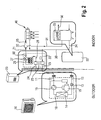
- the outdoor unit comprises an evaporator and/or condenser 14, a four-way valve 16, a compressor 15 and an expansion device 13, which is may be an electric valve or a capillary.
- the indoor unit 20 inter alia comprises a condenser/evaporator 25. These components form a heat pump.
- the evaporator/condenser 14, the compressor 15, the condenser/evaporator 25 and the expansion means 13 are connected in this order in a cycle or loop by means of a refrigerant piping 17, 18.
- a refrigerant is circulated by means of the compressor 15 in the refrigerant piping 17, 18. In the heating mode the refrigerant circulates clockwise in Fig. 2 .
- the refrigerant leaving the condenser 25 and having a first temperature T 1 upstream of the expansion means 13 passes the expansion means 13, the pressure being reduced. Afterwards, the refrigerant passes the evaporator 14 and is evaporated having a second temperature T 2 downstream of the evaporator higher than the first temperature. After leaving the evaporator 14, the refrigerant passes through the compressor, the pressure being increased. Finally, the refrigerant is again condensed to the first temperature T 1 in the condenser 25, wherein the heat from the refrigerant is transferred to the water or brine solution (fluid) in the piping connected to the indoor unit via the connections (inlet 22 and outlet 21.
- the indoor unit 20 further comprises a pump 27 and a backup heater 26.
- the pump serves for circulating the fluid (heating or cooling fluid) in the fluid circuit (21, 31, 34, 35, 36, 22).
- the purpose of the backup heater 26 is to cope with situations in which the heat pump described above is not capable to satisfy the entire heating demand (at very low temperatures, e.g. below -10°C). This backup heater 26 in some cases may also be omitted.
- the fluid enters the indoor unit 20 through the inlet 22, passes the condenser 25, wherein heat is transferred from the refrigerant to the fluid, then flows through the backup heater 26 in which the fluid may be additionally heated if necessary and subsequently passes the pump 27 which circulates the fluid in the fluid circuit. Afterwards and by controlling the valve 32 the fluid is either supplied to the floor heating loops 40 and the heat emitter 41 (see Fig. 1 ) or alternatively to the hot water tank piping (31, 34).
- the fluid may enter the hot water tank 30 by means of the piping 31 passing the heating coil inside the hot water tank 30 thereby transferring the heat from the fluid to the water contained in the hot water tank 30 and subsequently being refed to the circuit by the pipings 34 and 36 finally being reintroduced into the indoor unit via the inlet 22.
- the fluid may also be supplied to the floor heating loops 40 as a heat emitter or the radiator 41 shown in Fig. 1 and subsequently be reintroduced in to the indoor unit via the inlet 22.
- an additional (booster) heater 33 may be provided in the hot water tank.
- a temperature sensor 28 for measuring the temperature of the heating medium leaving the condenser 25 which in the following is referred to as T lwc is provided.
- T lwc the flow temperature of the heating medium may also be measured upstream of the condenser 25.
- the flow temperature T lwc will be set by the control to e.g. 25°C, which in turn leads to a flow temperature T f of 25°C. If the outdoor temperature T ambient decreases the set flow temperature T lwc will be linearly decreased and in the example will be set to 38°C corresponding to an outdoor temperature of -10°C. This flow temperature leads to a floor temperature of 30°C. The range between -10°C to 18°C is said to cover most of the days during the year in an average European country and an average year.
- the room heating of the present invention is capable of providing a floor temperature in a range between 22°C and 30°C, wherein the flow temperature is closely related to the outdoor temperature and in most cases of the year will result in the floor temperature between 22°C and 30°c which is perceived as a comfortable floor temperature.
- the condensing temperature is closely related to the flow temperature T lwc and increases with an increasing flow temperature and decreases with a decreasing flow temperature.
- the condensing temperature T c is also adapted based on the outdoor temperature.
- the efficiency depends on the difference between the temperature indoor (flow temperature) and the outdoor temperature. I.e. at low outdoor temperature of below -5°C, the efficiency rapidly drops.
- the compressor of the heat pump of the present invention preferably is inverter controlled so that the compressor frequency may be adapted to the required heating load and/or the outdoor temperature, respectively.
- Fig. 5 there is shown a schematic diagram showing the efficiency of the system relative to the compressor frequency or the outdoor temperature.
- the efficiency of the installation may reach a limit L at intermediate outdoor temperatures but a very low efficiency at high temperatures of about 18°C and above and very low temperatures at about 10°C and lower. This is visualized by the curve 63 in Fig. 5 .
- the flow temperature is adapted to the outdoor temperature in that the lower the outdoor temperature becomes the higher becomes the flow temperature and vice versa.
- a lower condensing temperature T c is required.
- the condensing temperature T c is reduced accordingly, leading to an increased efficiency in higher temperature ranges as depicted by the curve 64 in Fig.5 .
- a higher efficiency limit H may be obtained.
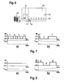
- Fig. 6 shows the installation of Figs. 1 and 2 in a schematic view and showing a room 60 to be heated.
- the heating medium piping is connected to the floor heating loops 40 in the room 60 via a valve 61.
- the floor heating loops 40 serve as a heat emitter to emit heat 26 for heating the room.
- the valve 61 is formed to communicate with a room thermostat RT 29, wherein a desired room temperature may be input (set) in the room thermostat 29 by a user. Based on the result of a comparison between the desired room temperature and the actual room temperature, the room thermostat 29 controls a valve 61 to either supply heating medium to the floor heating loops 40 or close a valve 61 in order not to supply any further heating medium to the floor heating loops 40.
- Figs. 7 and 8 compare an installation in which the flow temperature is not adapted based on the room temperature ( Figs. 7a and 8a ) and an installation according to the present invention in which the flow temperature Tlwc is adapted based on the room temperature.
- the room thermostat 29 has a very high cycling rate between an ON-Cycle and an OFF-Cycle over a predetermined period of time.
- the present invention suggests adapting the flow temperature T lwc based on the room temperature and in the present invention based on the period of time during which heating medium is supplied to the heat emitter, i.e. in which the room thermostat 29 (RT) is in the ON-Cycle.
- the present invention suggests a control which is configured to compare the time t 1* of the on cycle with a predetermined time t p . If t 1* ⁇ t p the flow temperature T lwc is decreased as shown in Fig. 7b ). This results in a longer period of time t 3* of an OFF-Cycle and to a longer period of time t 2* in an ON-Cycle.
- Fig. 8 shows in Fig. 8a ) a room heating which does not adapt the flow temperature with respect to the room temperature of the room to be heated.
- the flow temperature T lwc is too low to obtain the desired room temperature in the room 60.
- the room thermostat 29 remains continuously in the ON-Cycle controlling the valve 61 to supply heating medium to the floor heating loops 40.
- the flow temperature T lwc is increased so that an OFF-Cycle t 5* follows then again followed by an ON-Cycle t 6* .
- An example of the predetermined time t p resides in the range of 600 to 1800 seconds and preferably between 900 to 1500, preferably of 1200 seconds.
- the adaption of the flow temperature based on the room temperature may be based on an average of the aforesaid calculation with respect to Figs. 7 and 8 .
- the system compares the cycling rate of the thermostat in all of the rooms to be heated and based on each cycle adapts the flow temperature so as to obtain the most appropriate result for all rooms.
- the present invention is not limited to floor heating loops 40 but may also be applied to rooms heated by a conventional radiator 41 as heat emitter.
- a control configured to set the flow temperature of the heating medium based on only the outdoor temperature rather than the outdoor temperature and the room temperature already leads to an increase in efficiency compared to existing systems.
- such a control in combination with an inverter controlled compressor may be used separately without the additional adaption of the flow temperature based on the room temperature as explained with respect to Figs. 6 to 8 .
- the present invention is not limited to the room heating system explained with respect to Figs.
- the flow temperature does not necessarily have to be the temperature leaving the condenser 25 but may also be the temperature entering the condenser.
Landscapes
- Engineering & Computer Science (AREA)
- Chemical & Material Sciences (AREA)
- Combustion & Propulsion (AREA)
- Mechanical Engineering (AREA)
- General Engineering & Computer Science (AREA)
- Physics & Mathematics (AREA)
- Thermal Sciences (AREA)
- Steam Or Hot-Water Central Heating Systems (AREA)
- Central Heating Systems (AREA)
- Heating, Cooling, Or Curing Plastics Or The Like In General (AREA)
Priority Applications (3)
| Application Number | Priority Date | Filing Date | Title |
|---|---|---|---|
| EP08005304A EP2103884B1 (fr) | 2008-03-20 | 2008-03-20 | Chauffage d'une salle et procédé de contrôle du chauffage d'une salle |
| AT08005304T ATE507439T1 (de) | 2008-03-20 | 2008-03-20 | Raumheizung und verfahren zur steuerung der raumheizung |
| DE602008006519T DE602008006519D1 (de) | 2008-03-20 | 2008-03-20 | Raumheizung und Verfahren zur Steuerung der Raumheizung |
Applications Claiming Priority (1)
| Application Number | Priority Date | Filing Date | Title |
|---|---|---|---|
| EP08005304A EP2103884B1 (fr) | 2008-03-20 | 2008-03-20 | Chauffage d'une salle et procédé de contrôle du chauffage d'une salle |
Publications (2)
| Publication Number | Publication Date |
|---|---|
| EP2103884A1 true EP2103884A1 (fr) | 2009-09-23 |
| EP2103884B1 EP2103884B1 (fr) | 2011-04-27 |
Family
ID=39616554
Family Applications (1)
| Application Number | Title | Priority Date | Filing Date |
|---|---|---|---|
| EP08005304A Active EP2103884B1 (fr) | 2008-03-20 | 2008-03-20 | Chauffage d'une salle et procédé de contrôle du chauffage d'une salle |
Country Status (3)
| Country | Link |
|---|---|
| EP (1) | EP2103884B1 (fr) |
| AT (1) | ATE507439T1 (fr) |
| DE (1) | DE602008006519D1 (fr) |
Cited By (12)
| Publication number | Priority date | Publication date | Assignee | Title |
|---|---|---|---|---|
| GB2485623A (en) * | 2011-02-11 | 2012-05-23 | Esg Pool Ventilation Ltd | Heating system and method of heating an area by control of evaporating and/or condensing temperature of a refrigerant |
| WO2012125099A1 (fr) * | 2011-03-11 | 2012-09-20 | Forslund Jan | Procédé et installation pour réguler la température intérieure dans une pièce |
| EP2363659A4 (fr) * | 2010-01-08 | 2012-10-31 | Daikin Ind Ltd | Radiateur |
| EP2667106A1 (fr) * | 2012-05-22 | 2013-11-27 | Compagnie Industrielle D'Applications Thermiques | Kit et méthode de mise en oeuvre d'une installation de régulation de température pour un bâtiment |
| WO2016051336A1 (fr) * | 2014-10-03 | 2016-04-07 | Manfroi Giovanni | Système de chauffage en hiver et de climatisation en été |
| EP2972010A4 (fr) * | 2013-03-13 | 2017-05-10 | Rheem Manufacturing Company | Appareil et procédés pour chauffer de l'eau avec un réfrigérant venant d'un système de climatisation |
| EP2420747A3 (fr) * | 2010-08-17 | 2018-04-11 | LG Electronics, Inc. | Pompe à chaleur |
| US9945587B2 (en) | 2014-09-02 | 2018-04-17 | Rheem Manufacturing Company | Apparatus and method for hybrid water heating and air cooling and control thereof |
| EP4279823A1 (fr) * | 2022-05-18 | 2023-11-22 | Guangdong Carrier HVAC Co., Ltd. | Système de commande de module hydraulique de climatiseur multi-bloc de chauffage au sol et son procédé de commande |
| EP4296581A1 (fr) * | 2022-06-23 | 2023-12-27 | Global Piping Systems, S.L. | Installation de climatisation |
| US12173909B2 (en) | 2020-07-13 | 2024-12-24 | Rheem Manufacturing Company | Integrated space conditioning and water heating/cooling systems and methods thereto |
| US12449139B2 (en) | 2020-11-02 | 2025-10-21 | Rheem Manufacturing Company | Combined space and water heating systems |
Citations (7)
| Publication number | Priority date | Publication date | Assignee | Title |
|---|---|---|---|---|
| US2713252A (en) * | 1952-05-07 | 1955-07-19 | Little Inc A | Temperature control system |
| EP0157745A1 (fr) | 1984-03-02 | 1985-10-09 | Tour & Andersson Ab | Dispositif de régulation de température pour système de chauffage |
| GB2176275A (en) * | 1985-06-10 | 1986-12-17 | British Gas Corp | Apparatus for controlling the temperature of the circulating water in a central heating system |
| US4645908A (en) | 1984-07-27 | 1987-02-24 | Uhr Corporation | Residential heating, cooling and energy management system |
| JPH0282047A (ja) * | 1988-09-20 | 1990-03-22 | Sanden Corp | 多室形住棟用空調装置 |
| EP1113233A2 (fr) * | 1999-12-27 | 2001-07-04 | Carrier Corporation | Système de pompe à chaleur réversible |
| JP2007198632A (ja) * | 2006-01-24 | 2007-08-09 | Denso Corp | ヒートポンプ式給湯装置 |
-
2008
- 2008-03-20 AT AT08005304T patent/ATE507439T1/de not_active IP Right Cessation
- 2008-03-20 EP EP08005304A patent/EP2103884B1/fr active Active
- 2008-03-20 DE DE602008006519T patent/DE602008006519D1/de active Active
Patent Citations (7)
| Publication number | Priority date | Publication date | Assignee | Title |
|---|---|---|---|---|
| US2713252A (en) * | 1952-05-07 | 1955-07-19 | Little Inc A | Temperature control system |
| EP0157745A1 (fr) | 1984-03-02 | 1985-10-09 | Tour & Andersson Ab | Dispositif de régulation de température pour système de chauffage |
| US4645908A (en) | 1984-07-27 | 1987-02-24 | Uhr Corporation | Residential heating, cooling and energy management system |
| GB2176275A (en) * | 1985-06-10 | 1986-12-17 | British Gas Corp | Apparatus for controlling the temperature of the circulating water in a central heating system |
| JPH0282047A (ja) * | 1988-09-20 | 1990-03-22 | Sanden Corp | 多室形住棟用空調装置 |
| EP1113233A2 (fr) * | 1999-12-27 | 2001-07-04 | Carrier Corporation | Système de pompe à chaleur réversible |
| JP2007198632A (ja) * | 2006-01-24 | 2007-08-09 | Denso Corp | ヒートポンプ式給湯装置 |
Cited By (20)
| Publication number | Priority date | Publication date | Assignee | Title |
|---|---|---|---|---|
| EP2363659A4 (fr) * | 2010-01-08 | 2012-10-31 | Daikin Ind Ltd | Radiateur |
| EP2420747A3 (fr) * | 2010-08-17 | 2018-04-11 | LG Electronics, Inc. | Pompe à chaleur |
| US9328931B2 (en) | 2011-02-11 | 2016-05-03 | Esg Pool Ventilation Ltd | Heating and/or cooling system for maintaining an environment at a desired temperature |
| GB2485623B (en) * | 2011-02-11 | 2012-10-17 | Esg Pool Ventilation Ltd | Heating and/or cooling system and related methods |
| GB2485623A (en) * | 2011-02-11 | 2012-05-23 | Esg Pool Ventilation Ltd | Heating system and method of heating an area by control of evaporating and/or condensing temperature of a refrigerant |
| WO2012125099A1 (fr) * | 2011-03-11 | 2012-09-20 | Forslund Jan | Procédé et installation pour réguler la température intérieure dans une pièce |
| FR2991029A1 (fr) * | 2012-05-22 | 2013-11-29 | Ciat Sa | Kit et methode de mise en oeuvre d'une installation de regulation de temperature pour un batiment |
| EP2667106A1 (fr) * | 2012-05-22 | 2013-11-27 | Compagnie Industrielle D'Applications Thermiques | Kit et méthode de mise en oeuvre d'une installation de régulation de température pour un bâtiment |
| US10871307B2 (en) | 2013-03-13 | 2020-12-22 | Rheem Manufacturing Company | Apparatus and methods for heating water with refrigerant from air conditioning system |
| EP2972010A4 (fr) * | 2013-03-13 | 2017-05-10 | Rheem Manufacturing Company | Appareil et procédés pour chauffer de l'eau avec un réfrigérant venant d'un système de climatisation |
| US9879881B2 (en) | 2013-03-13 | 2018-01-30 | Rheem Manufacturing Company | Apparatus and methods for heating water with refrigerant from air conditioning system |
| US12203683B2 (en) | 2013-03-13 | 2025-01-21 | Rheem Manufacturing Company | Apparatus and methods for heating water with refrigerant from air conditioning system |
| US9945582B2 (en) | 2013-03-13 | 2018-04-17 | Rheem Manufacturing Company | Apparatus and methods for pre-heating water with air conditioning unit or heat pump |
| US10041702B2 (en) | 2014-09-02 | 2018-08-07 | Rheem Manufacturing Company | Apparatus and method for hybrid water heating and air cooling and control thereof |
| US9945587B2 (en) | 2014-09-02 | 2018-04-17 | Rheem Manufacturing Company | Apparatus and method for hybrid water heating and air cooling and control thereof |
| WO2016051336A1 (fr) * | 2014-10-03 | 2016-04-07 | Manfroi Giovanni | Système de chauffage en hiver et de climatisation en été |
| US12173909B2 (en) | 2020-07-13 | 2024-12-24 | Rheem Manufacturing Company | Integrated space conditioning and water heating/cooling systems and methods thereto |
| US12449139B2 (en) | 2020-11-02 | 2025-10-21 | Rheem Manufacturing Company | Combined space and water heating systems |
| EP4279823A1 (fr) * | 2022-05-18 | 2023-11-22 | Guangdong Carrier HVAC Co., Ltd. | Système de commande de module hydraulique de climatiseur multi-bloc de chauffage au sol et son procédé de commande |
| EP4296581A1 (fr) * | 2022-06-23 | 2023-12-27 | Global Piping Systems, S.L. | Installation de climatisation |
Also Published As
| Publication number | Publication date |
|---|---|
| EP2103884B1 (fr) | 2011-04-27 |
| ATE507439T1 (de) | 2011-05-15 |
| DE602008006519D1 (de) | 2011-06-09 |
Similar Documents
| Publication | Publication Date | Title |
|---|---|---|
| EP2103884B1 (fr) | Chauffage d'une salle et procédé de contrôle du chauffage d'une salle | |
| US9562701B2 (en) | Temperature control system and air conditioning system | |
| KR950011376B1 (ko) | 가변 속도 열 펌프를 사용하는 공간 난방 및 물 가열 제어 방법 | |
| JP5073970B2 (ja) | ヒートポンプ給湯床暖房装置 | |
| CN102865646B (zh) | 空气调节器 | |
| JP5524571B2 (ja) | ヒートポンプ装置 | |
| EP2508806B1 (fr) | Système de pompe à chaleur et procédé de commande de l'unité de pompe à chaleur | |
| EP2103890B1 (fr) | Dispositif de chauffage et procédé de contrôle du chauffage | |
| US20110138839A1 (en) | Water circulation apparatus associated with refrigerant system | |
| JP5605296B2 (ja) | ハイブリッド式給湯装置 | |
| WO2014181401A1 (fr) | Appareil de circulation et de chauffage | |
| US10436463B2 (en) | Air-conditioning apparatus | |
| EP3258185B1 (fr) | Système d'alimentation en chaleur | |
| JP5482724B2 (ja) | ハイブリッド式給湯装置 | |
| AU2009227388B8 (en) | Heating and method for controlling the heating | |
| US11353234B2 (en) | Air conditioning system | |
| US7628337B2 (en) | Secondary heating system | |
| JP5677198B2 (ja) | 空冷ヒートポンプチラー | |
| CN103119373B (zh) | 热水优先化 | |
| JP7471247B2 (ja) | 流体循環式加熱システム | |
| CN209027144U (zh) | 一种空调 | |
| JP4169453B2 (ja) | 貯湯式の給湯熱源装置 | |
| JP2002295899A (ja) | 貯湯式の給湯熱源装置 | |
| JP3594426B2 (ja) | 空調装置 | |
| JP2008116184A (ja) | 冷凍サイクル装置 |
Legal Events
| Date | Code | Title | Description |
|---|---|---|---|
| PUAI | Public reference made under article 153(3) epc to a published international application that has entered the european phase |
Free format text: ORIGINAL CODE: 0009012 |
|
| AK | Designated contracting states |
Kind code of ref document: A1 Designated state(s): AT BE BG CH CY CZ DE DK EE ES FI FR GB GR HR HU IE IS IT LI LT LU LV MC MT NL NO PL PT RO SE SI SK TR |
|
| AX | Request for extension of the european patent |
Extension state: AL BA MK RS |
|
| 17P | Request for examination filed |
Effective date: 20100310 |
|
| AKX | Designation fees paid |
Designated state(s): AT BE BG CH CY CZ DE DK EE ES FI FR GB GR HR HU IE IS IT LI LT LU LV MC MT NL NO PL PT RO SE SI SK TR |
|
| 17Q | First examination report despatched |
Effective date: 20100628 |
|
| GRAP | Despatch of communication of intention to grant a patent |
Free format text: ORIGINAL CODE: EPIDOSNIGR1 |
|
| GRAS | Grant fee paid |
Free format text: ORIGINAL CODE: EPIDOSNIGR3 |
|
| GRAA | (expected) grant |
Free format text: ORIGINAL CODE: 0009210 |
|
| AK | Designated contracting states |
Kind code of ref document: B1 Designated state(s): AT BE BG CH CY CZ DE DK EE ES FI FR GB GR HR HU IE IS IT LI LT LU LV MC MT NL NO PL PT RO SE SI SK TR |
|
| REG | Reference to a national code |
Ref country code: GB Ref legal event code: FG4D |
|
| REG | Reference to a national code |
Ref country code: CH Ref legal event code: EP |
|
| REG | Reference to a national code |
Ref country code: IE Ref legal event code: FG4D |
|
| REF | Corresponds to: |
Ref document number: 602008006519 Country of ref document: DE Date of ref document: 20110609 Kind code of ref document: P |
|
| REG | Reference to a national code |
Ref country code: DE Ref legal event code: R096 Ref document number: 602008006519 Country of ref document: DE Effective date: 20110609 |
|
| REG | Reference to a national code |
Ref country code: SE Ref legal event code: TRGR |
|
| REG | Reference to a national code |
Ref country code: NL Ref legal event code: VDEP Effective date: 20110427 |
|
| LTIE | Lt: invalidation of european patent or patent extension |
Effective date: 20110427 |
|
| PG25 | Lapsed in a contracting state [announced via postgrant information from national office to epo] |
Ref country code: LT Free format text: LAPSE BECAUSE OF FAILURE TO SUBMIT A TRANSLATION OF THE DESCRIPTION OR TO PAY THE FEE WITHIN THE PRESCRIBED TIME-LIMIT Effective date: 20110427 Ref country code: HR Free format text: LAPSE BECAUSE OF FAILURE TO SUBMIT A TRANSLATION OF THE DESCRIPTION OR TO PAY THE FEE WITHIN THE PRESCRIBED TIME-LIMIT Effective date: 20110427 Ref country code: PT Free format text: LAPSE BECAUSE OF FAILURE TO SUBMIT A TRANSLATION OF THE DESCRIPTION OR TO PAY THE FEE WITHIN THE PRESCRIBED TIME-LIMIT Effective date: 20110829 Ref country code: NO Free format text: LAPSE BECAUSE OF FAILURE TO SUBMIT A TRANSLATION OF THE DESCRIPTION OR TO PAY THE FEE WITHIN THE PRESCRIBED TIME-LIMIT Effective date: 20110727 |
|
| PG25 | Lapsed in a contracting state [announced via postgrant information from national office to epo] |
Ref country code: ES Free format text: LAPSE BECAUSE OF FAILURE TO SUBMIT A TRANSLATION OF THE DESCRIPTION OR TO PAY THE FEE WITHIN THE PRESCRIBED TIME-LIMIT Effective date: 20110807 Ref country code: CY Free format text: LAPSE BECAUSE OF FAILURE TO SUBMIT A TRANSLATION OF THE DESCRIPTION OR TO PAY THE FEE WITHIN THE PRESCRIBED TIME-LIMIT Effective date: 20110427 Ref country code: GR Free format text: LAPSE BECAUSE OF FAILURE TO SUBMIT A TRANSLATION OF THE DESCRIPTION OR TO PAY THE FEE WITHIN THE PRESCRIBED TIME-LIMIT Effective date: 20110728 Ref country code: IS Free format text: LAPSE BECAUSE OF FAILURE TO SUBMIT A TRANSLATION OF THE DESCRIPTION OR TO PAY THE FEE WITHIN THE PRESCRIBED TIME-LIMIT Effective date: 20110827 Ref country code: LV Free format text: LAPSE BECAUSE OF FAILURE TO SUBMIT A TRANSLATION OF THE DESCRIPTION OR TO PAY THE FEE WITHIN THE PRESCRIBED TIME-LIMIT Effective date: 20110427 Ref country code: AT Free format text: LAPSE BECAUSE OF FAILURE TO SUBMIT A TRANSLATION OF THE DESCRIPTION OR TO PAY THE FEE WITHIN THE PRESCRIBED TIME-LIMIT Effective date: 20110427 Ref country code: SI Free format text: LAPSE BECAUSE OF FAILURE TO SUBMIT A TRANSLATION OF THE DESCRIPTION OR TO PAY THE FEE WITHIN THE PRESCRIBED TIME-LIMIT Effective date: 20110427 Ref country code: FI Free format text: LAPSE BECAUSE OF FAILURE TO SUBMIT A TRANSLATION OF THE DESCRIPTION OR TO PAY THE FEE WITHIN THE PRESCRIBED TIME-LIMIT Effective date: 20110427 |
|
| PG25 | Lapsed in a contracting state [announced via postgrant information from national office to epo] |
Ref country code: NL Free format text: LAPSE BECAUSE OF FAILURE TO SUBMIT A TRANSLATION OF THE DESCRIPTION OR TO PAY THE FEE WITHIN THE PRESCRIBED TIME-LIMIT Effective date: 20110427 |
|
| PG25 | Lapsed in a contracting state [announced via postgrant information from national office to epo] |
Ref country code: EE Free format text: LAPSE BECAUSE OF FAILURE TO SUBMIT A TRANSLATION OF THE DESCRIPTION OR TO PAY THE FEE WITHIN THE PRESCRIBED TIME-LIMIT Effective date: 20110427 |
|
| PG25 | Lapsed in a contracting state [announced via postgrant information from national office to epo] |
Ref country code: RO Free format text: LAPSE BECAUSE OF FAILURE TO SUBMIT A TRANSLATION OF THE DESCRIPTION OR TO PAY THE FEE WITHIN THE PRESCRIBED TIME-LIMIT Effective date: 20110427 Ref country code: SK Free format text: LAPSE BECAUSE OF FAILURE TO SUBMIT A TRANSLATION OF THE DESCRIPTION OR TO PAY THE FEE WITHIN THE PRESCRIBED TIME-LIMIT Effective date: 20110427 Ref country code: DK Free format text: LAPSE BECAUSE OF FAILURE TO SUBMIT A TRANSLATION OF THE DESCRIPTION OR TO PAY THE FEE WITHIN THE PRESCRIBED TIME-LIMIT Effective date: 20110427 Ref country code: PL Free format text: LAPSE BECAUSE OF FAILURE TO SUBMIT A TRANSLATION OF THE DESCRIPTION OR TO PAY THE FEE WITHIN THE PRESCRIBED TIME-LIMIT Effective date: 20110427 |
|
| PLBE | No opposition filed within time limit |
Free format text: ORIGINAL CODE: 0009261 |
|
| STAA | Information on the status of an ep patent application or granted ep patent |
Free format text: STATUS: NO OPPOSITION FILED WITHIN TIME LIMIT |
|
| 26N | No opposition filed |
Effective date: 20120130 |
|
| REG | Reference to a national code |
Ref country code: DE Ref legal event code: R097 Ref document number: 602008006519 Country of ref document: DE Effective date: 20120130 |
|
| PG25 | Lapsed in a contracting state [announced via postgrant information from national office to epo] |
Ref country code: IT Free format text: LAPSE BECAUSE OF FAILURE TO SUBMIT A TRANSLATION OF THE DESCRIPTION OR TO PAY THE FEE WITHIN THE PRESCRIBED TIME-LIMIT Effective date: 20110427 |
|
| PG25 | Lapsed in a contracting state [announced via postgrant information from national office to epo] |
Ref country code: MC Free format text: LAPSE BECAUSE OF NON-PAYMENT OF DUE FEES Effective date: 20120331 |
|
| REG | Reference to a national code |
Ref country code: CH Ref legal event code: PL |
|
| REG | Reference to a national code |
Ref country code: IE Ref legal event code: MM4A |
|
| PG25 | Lapsed in a contracting state [announced via postgrant information from national office to epo] |
Ref country code: CH Free format text: LAPSE BECAUSE OF NON-PAYMENT OF DUE FEES Effective date: 20120331 Ref country code: IE Free format text: LAPSE BECAUSE OF NON-PAYMENT OF DUE FEES Effective date: 20120320 Ref country code: LI Free format text: LAPSE BECAUSE OF NON-PAYMENT OF DUE FEES Effective date: 20120331 |
|
| PG25 | Lapsed in a contracting state [announced via postgrant information from national office to epo] |
Ref country code: BG Free format text: LAPSE BECAUSE OF FAILURE TO SUBMIT A TRANSLATION OF THE DESCRIPTION OR TO PAY THE FEE WITHIN THE PRESCRIBED TIME-LIMIT Effective date: 20110727 |
|
| PG25 | Lapsed in a contracting state [announced via postgrant information from national office to epo] |
Ref country code: MT Free format text: LAPSE BECAUSE OF FAILURE TO SUBMIT A TRANSLATION OF THE DESCRIPTION OR TO PAY THE FEE WITHIN THE PRESCRIBED TIME-LIMIT Effective date: 20110427 |
|
| PG25 | Lapsed in a contracting state [announced via postgrant information from national office to epo] |
Ref country code: TR Free format text: LAPSE BECAUSE OF FAILURE TO SUBMIT A TRANSLATION OF THE DESCRIPTION OR TO PAY THE FEE WITHIN THE PRESCRIBED TIME-LIMIT Effective date: 20110427 |
|
| PG25 | Lapsed in a contracting state [announced via postgrant information from national office to epo] |
Ref country code: LU Free format text: LAPSE BECAUSE OF NON-PAYMENT OF DUE FEES Effective date: 20120320 |
|
| PG25 | Lapsed in a contracting state [announced via postgrant information from national office to epo] |
Ref country code: HU Free format text: LAPSE BECAUSE OF FAILURE TO SUBMIT A TRANSLATION OF THE DESCRIPTION OR TO PAY THE FEE WITHIN THE PRESCRIBED TIME-LIMIT Effective date: 20080320 |
|
| REG | Reference to a national code |
Ref country code: FR Ref legal event code: PLFP Year of fee payment: 9 |
|
| REG | Reference to a national code |
Ref country code: FR Ref legal event code: PLFP Year of fee payment: 10 |
|
| REG | Reference to a national code |
Ref country code: FR Ref legal event code: PLFP Year of fee payment: 11 |
|
| P01 | Opt-out of the competence of the unified patent court (upc) registered |
Effective date: 20230530 |
|
| PGFP | Annual fee paid to national office [announced via postgrant information from national office to epo] |
Ref country code: CZ Payment date: 20240228 Year of fee payment: 17 |
|
| PGFP | Annual fee paid to national office [announced via postgrant information from national office to epo] |
Ref country code: SE Payment date: 20240212 Year of fee payment: 17 |
|
| PG25 | Lapsed in a contracting state [announced via postgrant information from national office to epo] |
Ref country code: CZ Free format text: LAPSE BECAUSE OF NON-PAYMENT OF DUE FEES Effective date: 20250320 |
|
| REG | Reference to a national code |
Ref country code: SE Ref legal event code: EUG |
|
| PG25 | Lapsed in a contracting state [announced via postgrant information from national office to epo] |
Ref country code: SE Free format text: LAPSE BECAUSE OF NON-PAYMENT OF DUE FEES Effective date: 20250321 |
|
| PGFP | Annual fee paid to national office [announced via postgrant information from national office to epo] |
Ref country code: GB Payment date: 20260202 Year of fee payment: 19 |
|
| PGFP | Annual fee paid to national office [announced via postgrant information from national office to epo] |
Ref country code: DE Payment date: 20260128 Year of fee payment: 19 |
|
| PGFP | Annual fee paid to national office [announced via postgrant information from national office to epo] |
Ref country code: BE Payment date: 20260216 Year of fee payment: 19 |
|
| PGFP | Annual fee paid to national office [announced via postgrant information from national office to epo] |
Ref country code: FR Payment date: 20260209 Year of fee payment: 19 |