EP2103913A2 - Électronique de compteur et procédés pour diagnostic de vérification de débitmètre - Google Patents
Électronique de compteur et procédés pour diagnostic de vérification de débitmètre Download PDFInfo
- Publication number
- EP2103913A2 EP2103913A2 EP09165263A EP09165263A EP2103913A2 EP 2103913 A2 EP2103913 A2 EP 2103913A2 EP 09165263 A EP09165263 A EP 09165263A EP 09165263 A EP09165263 A EP 09165263A EP 2103913 A2 EP2103913 A2 EP 2103913A2
- Authority
- EP
- European Patent Office
- Prior art keywords
- stiffness
- pole
- frequency response
- parameter
- residue
- Prior art date
- Legal status (The legal status is an assumption and is not a legal conclusion. Google has not performed a legal analysis and makes no representation as to the accuracy of the status listed.)
- Granted
Links
Images


Classifications
-
- G—PHYSICS
- G01—MEASURING; TESTING
- G01F—MEASURING VOLUME, VOLUME FLOW, MASS FLOW OR LIQUID LEVEL; METERING BY VOLUME
- G01F1/00—Measuring the volume flow or mass flow of fluid or fluent solid material wherein the fluid passes through a meter in a continuous flow
- G01F1/76—Devices for measuring mass flow of a fluid or a fluent solid material
- G01F1/78—Direct mass flowmeters
- G01F1/80—Direct mass flowmeters operating by measuring pressure, force, momentum, or frequency of a fluid flow to which a rotational movement has been imparted
- G01F1/84—Coriolis or gyroscopic mass flowmeters
- G01F1/845—Coriolis or gyroscopic mass flowmeters arrangements of measuring means, e.g., of measuring conduits
- G01F1/8468—Coriolis or gyroscopic mass flowmeters arrangements of measuring means, e.g., of measuring conduits vibrating measuring conduits
- G01F1/8472—Coriolis or gyroscopic mass flowmeters arrangements of measuring means, e.g., of measuring conduits vibrating measuring conduits having curved measuring conduits, i.e. whereby the measuring conduits' curved center line lies within a plane
- G01F1/8477—Coriolis or gyroscopic mass flowmeters arrangements of measuring means, e.g., of measuring conduits vibrating measuring conduits having curved measuring conduits, i.e. whereby the measuring conduits' curved center line lies within a plane with multiple measuring conduits
-
- G—PHYSICS
- G01—MEASURING; TESTING
- G01F—MEASURING VOLUME, VOLUME FLOW, MASS FLOW OR LIQUID LEVEL; METERING BY VOLUME
- G01F1/00—Measuring the volume flow or mass flow of fluid or fluent solid material wherein the fluid passes through a meter in a continuous flow
- G01F1/76—Devices for measuring mass flow of a fluid or a fluent solid material
- G01F1/78—Direct mass flowmeters
- G01F1/80—Direct mass flowmeters operating by measuring pressure, force, momentum, or frequency of a fluid flow to which a rotational movement has been imparted
- G01F1/84—Coriolis or gyroscopic mass flowmeters
- G01F1/8409—Coriolis or gyroscopic mass flowmeters constructional details
- G01F1/8413—Coriolis or gyroscopic mass flowmeters constructional details means for influencing the flowmeter's motional or vibrational behaviour, e.g., conduit support or fixing means, or conduit attachments
-
- G—PHYSICS
- G01—MEASURING; TESTING
- G01F—MEASURING VOLUME, VOLUME FLOW, MASS FLOW OR LIQUID LEVEL; METERING BY VOLUME
- G01F1/00—Measuring the volume flow or mass flow of fluid or fluent solid material wherein the fluid passes through a meter in a continuous flow
- G01F1/76—Devices for measuring mass flow of a fluid or a fluent solid material
- G01F1/78—Direct mass flowmeters
- G01F1/80—Direct mass flowmeters operating by measuring pressure, force, momentum, or frequency of a fluid flow to which a rotational movement has been imparted
- G01F1/84—Coriolis or gyroscopic mass flowmeters
- G01F1/8409—Coriolis or gyroscopic mass flowmeters constructional details
- G01F1/8431—Coriolis or gyroscopic mass flowmeters constructional details electronic circuits
-
- G—PHYSICS
- G01—MEASURING; TESTING
- G01F—MEASURING VOLUME, VOLUME FLOW, MASS FLOW OR LIQUID LEVEL; METERING BY VOLUME
- G01F1/00—Measuring the volume flow or mass flow of fluid or fluent solid material wherein the fluid passes through a meter in a continuous flow
- G01F1/76—Devices for measuring mass flow of a fluid or a fluent solid material
- G01F1/78—Direct mass flowmeters
- G01F1/80—Direct mass flowmeters operating by measuring pressure, force, momentum, or frequency of a fluid flow to which a rotational movement has been imparted
- G01F1/84—Coriolis or gyroscopic mass flowmeters
- G01F1/8409—Coriolis or gyroscopic mass flowmeters constructional details
- G01F1/8436—Coriolis or gyroscopic mass flowmeters constructional details signal processing
-
- G—PHYSICS
- G01—MEASURING; TESTING
- G01F—MEASURING VOLUME, VOLUME FLOW, MASS FLOW OR LIQUID LEVEL; METERING BY VOLUME
- G01F15/00—Details of, or accessories for, apparatus of groups G01F1/00 - G01F13/00 insofar as such details or appliances are not adapted to particular types of such apparatus
- G01F15/02—Compensating or correcting for variations in pressure, density or temperature
- G01F15/022—Compensating or correcting for variations in pressure, density or temperature using electrical means
- G01F15/024—Compensating or correcting for variations in pressure, density or temperature using electrical means involving digital counting
-
- G—PHYSICS
- G01—MEASURING; TESTING
- G01F—MEASURING VOLUME, VOLUME FLOW, MASS FLOW OR LIQUID LEVEL; METERING BY VOLUME
- G01F25/00—Testing or calibration of apparatus for measuring volume, volume flow or liquid level or for metering by volume
-
- G—PHYSICS
- G01—MEASURING; TESTING
- G01F—MEASURING VOLUME, VOLUME FLOW, MASS FLOW OR LIQUID LEVEL; METERING BY VOLUME
- G01F25/00—Testing or calibration of apparatus for measuring volume, volume flow or liquid level or for metering by volume
- G01F25/10—Testing or calibration of apparatus for measuring volume, volume flow or liquid level or for metering by volume of flowmeters
-
- G—PHYSICS
- G01—MEASURING; TESTING
- G01N—INVESTIGATING OR ANALYSING MATERIALS BY DETERMINING THEIR CHEMICAL OR PHYSICAL PROPERTIES
- G01N9/00—Investigating density or specific gravity of materials; Analysing materials by determining density or specific gravity
-
- G—PHYSICS
- G01—MEASURING; TESTING
- G01N—INVESTIGATING OR ANALYSING MATERIALS BY DETERMINING THEIR CHEMICAL OR PHYSICAL PROPERTIES
- G01N9/00—Investigating density or specific gravity of materials; Analysing materials by determining density or specific gravity
- G01N9/002—Investigating density or specific gravity of materials; Analysing materials by determining density or specific gravity using variation of the resonant frequency of an element vibrating in contact with the material submitted to analysis
Definitions
- the present invention relates to a meter electronics and methods for verification diagnostics for a flow meter.
- Vibrating conduit sensors such as Coriolis mass flow meters or vibrating tube densitometers, typically operate by detecting motion of a vibrating conduit that contains a flowing material. Properties associated with the material in the conduit, such as mass flow, density and the like, can be determined by processing measurement signals received from motion transducers associated with the conduit. The vibration modes of the vibrating material-filled system generally are affected by the combined mass, stiffness, and damping characteristics of the containing conduit and the material contained therein.
- a conduit of a vibratory flow meter can include one or more flow tubes.
- a flow tube is forced to vibrate at a resonant frequency, where the resonant frequency of the tube is proportional to the density of the fluid in the flow tube.
- Sensors located on the inlet and outlet sections of the tube measure the relative vibration between the ends of the tube.
- the vibrating tube and the flowing mass couple together due to Coriolis forces, causing a phase shift in the vibration between the ends of the tube.
- the phase shift is directly proportional to the mass flow.
- a typical Coriolis mass flow meter includes one or more conduits that are connected inline in a pipeline or other transport system and convey material, e . g ., fluids, slurries and the like, in the system.
- Each conduit may be viewed as having a set of natural vibration modes including, for example, simple bending, torsional, radial, and coupled modes.
- a conduit is excited in one or more vibration modes as a material flows through the conduit, and motion of the conduit is measured at points spaced along the conduit. Excitation is typically provided by an actuator, e . g ., an electromechanical device, such as a voice coil-type driver, that perturbs the conduit in a periodic fashion.
- Mass flow rate may be determined by measuring time delay or phase differences between motions at the transducer locations.
- Two such transducers or pickoff sensors are typically employed in order to measure a vibrational response of the flow conduit or conduits, and are typically located at positions upstream and downstream of the actuator.
- the two pickoff sensors are connected to electronic instrumentation by cabling.
- the instrumentation receives signals from the two pickoff sensors and processes the signals in order to derive a mass flow rate measurement.
- the phase difference between the two sensor signals is related to the mass flow rate of the material flowing through the flow tube or flow tubes.
- the mass flow rate of the material is proportional to the time delay between the two sensor signals, and the mass flow rate can therefore be determined by multiplying the time delay by a Flow Calibration Factor (FCF), where the time delay comprises a phase difference divided by frequency.
- FCF Flow Calibration Factor
- the FCF reflects the material properties and cross-sectional properties of the flow tube.
- the FCF is determined by a calibration process prior to installation of the flow meter into a pipeline or other conduit. In the calibration process, a fluid is passed through the flow tube at a given flow rate and the proportion between the phase difference and the flow rate is calculated.
- Coriolis flow meter One advantage of a Coriolis flow meter is that the accuracy of the measured mass flow rate is not affected by wear of moving components in the flow meter.
- the flow rate is determined by multiplying the phase difference between two points of the flow tube and the flow calibration factor.
- the only input is the sinusoidal signals from the sensors, indicating the oscillation of two points on the flow tube.
- the phase difference is calculated from these sinusoidal signals.
- the FCF can be related to a stiffness characteristic of the meter assembly. If the stiffness characteristic of the meter assembly changes, then the FCF will also change. Changes therefore will affect the accuracy of the flow measurements generated by the flow meter. Changes in the material and cross-sectional properties of a flow tube can be caused by erosion or corrosion, for example. Consequently, it is highly desirable to be able to detect and/or quantify any changes to the stiffness of the meter assembly in order to maintain a high level of accuracy in the flow meter.
- the meter electronics comprises an interface for receiving a vibrational response from the flow meter and a processing system in communication with the interface.
- the vibrational response comprises a response to a vibration of the flow meter at a substantially resonant frequency.
- the processing system is configured to receive the vibrational response from the interface, determine a frequency ( ⁇ 0 ) of the vibrational response, determine a response voltage (V) and a drive current (I) of the vibrational response, measure a decay characteristic ( ⁇ ) of the flow meter, and determine the stiffness parameter (K) from the frequency ( ⁇ 0 ), the response voltage (V), the drive current (I), and the decay characteristic ( ⁇ ).
- a method for determining a stiffness parameter (K) of a flow meter comprises receiving a vibrational response from the flow meter.
- the vibrational response comprises a response to a vibration of the flow meter at a substantially resonant frequency.
- the method further comprises determining a frequency ( ⁇ 0 ) of the vibrational response, determining a response voltage (V) and a drive current (I) of the vibrational response, and measuring a decay characteristic ( ⁇ ) of the flow meter.
- the method further comprises determining the stiffness parameter (K) from the frequency ( ⁇ 0 ), the response voltage (V), the drive current (I), and the decay characteristic ( ⁇ ).
- a method for determining a stiffness change ( ⁇ K) in a flow meter comprises receiving a vibrational response from the flow meter.
- the vibrational response comprises a response to a vibration of the flow meter at a substantially resonant frequency.
- the method further comprises determining a frequency ( ⁇ 0 ) of the vibrational response, determining a response voltage (V) and a drive current (I) of the vibrational response, and measuring a decay characteristic ( ⁇ ) of the flow meter.
- the method further comprises determining the stiffness parameter (K) from the frequency ( ⁇ 0 ), the response voltage (V), the drive current (I), and the decay characteristic ( ⁇ ).
- the method further comprises receiving a second vibrational response from the flow meter at a second time t 2 , generating a second stiffness characteristic (K 2 ) from the second vibrational response, comparing the second stiffness characteristic (K 2 ) to the stiffness parameter (K), and detecting the stiffness change ( ⁇ K) if the second stiffness characteristic (K 2 ) differs from the stiffness parameter (K) by more than a predetermined tolerance.
- the meter electronics comprises an interface for receiving three or more vibrational responses from the flow meter.
- the three or more vibrational responses include a substantially fundamental frequency response and two or more non-fundamental frequency responses.
- the meter electronics further comprises a processing system in communication with the interface and configured to receive the three or more vibrational responses from the interface, generate a pole-residue frequency response function from the three or more vibrational responses, and determine at least a stiffness parameter (K) from the pole-residue frequency response function.
- K stiffness parameter
- a method for determining a stiffness parameter (K) of a flow meter comprises receiving three or more vibrational responses.
- the three or more vibrational responses include a substantially fundamental frequency response and two or more non-fundamental frequency responses.
- the method further comprises generating a pole-residue frequency response function from the three or more vibrational responses and determining at least a stiffness parameter (K) from the pole-residue frequency response function.
- the method further comprises receiving a second set of three or more vibrational responses from the flow meter at a second time t 2 , generating a second stiffness characteristic (K 2 ) from the second set of three or more vibrational responses, comparing the second stiffness characteristic (K 2 ) to the stiffness parameter (K), and detecting the stiffness change ( ⁇ K) if the second stiffness characteristic (K 2 ) differs from the stiffness parameter (K) by more than a predetermined tolerance.
- measuring the decay characteristic ( ⁇ ) further comprises allowing the vibrational response of the flow meter to decay down to a predetermined vibrational target.
- the processing system is further configured to measure the decay characteristic ( ⁇ ) by removing the excitation of the flow meter and allowing the vibrational response of the flow meter to decay down to a predetermined vibrational target while measuring the decay characteristic.
- measuring the decay characteristic ( ⁇ ) further comprises allowing the vibrational response of the flow meter to decay down to a predetermined vibrational target.
- measuring the decay characteristic ( ⁇ ) further comprises removing the excitation of the flow meter and allowing the vibrational response of the flow meter to decay down to a predetermined vibrational target while measuring the decay characteristic.
- generating the second stiffness characteristic (K 2 )from the second vibrational response comprises generating the second stiffness characteristic (K 2 ) from a second frequency, a second response voltage, a second drive current, and a second damping characteristic.
- the method further comprises detecting the stiffness change ( ⁇ K) if the second stiffness characteristic (K 2 ) differs from the stiffness parameter (K) by more than a predetermined stiffness tolerance.
- the method further comprises quantifying the stiffness change ( ⁇ K) from the comparing of K and K 2 .
- the processing system is further configured to determine a damping parameter (C) from the pole-residue frequency response function.
- the processing system is further configured to determine a mass parameter (M) from the pole-residue frequency response function.
- the processing system is further configured to compute a pole ( ⁇ ), a left residue (R L ), and a right residue (R R ) from the pole-residue frequency response function.
- the three or more vibrational responses comprise at least one tone above the fundamental frequency response and at least one tone below the fundamental frequency response.
- the three or more vibrational responses comprise at least two tones above the fundamental frequency response and at least two tones below the fundamental frequency response.
- the pole-residue frequency response function comprises a first order pole-residue frequency response function.
- the pole-residue frequency response function comprises a second order pole-residue frequency response function.
- the determining comprises further determining a damping parameter (C) from the pole-residue frequency response function.
- the determining comprises further determining a mass parameter (M) from the pole-residue frequency response function.
- the determining further comprises computing a pole ( ⁇ ), a left residue (R L ), and a right residue (R R ) from the pole-residue frequency response function.
- the three or more vibrational responses comprise at least one tone above the fundamental frequency response and at least one tone below the fundamental frequency response.
- the three or more vibrational responses comprise at least two tones above the fundamental frequency response and at least two tones below the fundamental frequency response.
- the pole-residue frequency response function comprises a first order pole-residue frequency response function.
- the pole-residue frequency response function comprises a second order pole-residue frequency response function.
- the method further comprises detecting the stiffness change ( ⁇ K) if the second stiffness characteristic (K 2 ) differs from the stiffness parameter (K) by more than a predetermined stiffness tolerance.
- the method further comprises quantifying the stiffness change ( ⁇ K) from the comparing of K and K 2 .
- FIGS. 1-12 and the following description depict specific examples to teach those skilled in the art how to make and use the best mode of the invention. For the purpose of teaching inventive principles, some conventional aspects have been simplified or omitted. Those skilled in the art will appreciate variations from these examples that fall within the scope of the invention. Those skilled in the art will appreciate that the features described below can be combined in various ways to form multiple variations of the invention. As a result, the invention is not limited to the specific examples described below, but only by the claims and their equivalents.
- FIG. 1 shows a flow meter 5 comprising a meter assembly 10 and meter electronics 20.
- Meter assembly 10 responds to mass flow rate and density of a process material.
- Meter electronics 20 is connected to meter assembly 10 via leads 100 to provide density, mass flow rate, and temperature information over path 26, as well as other information not relevant to the present invention.
- a Coriolis flow meter structure is described although it is apparent to those skilled in the art that the present invention could be practiced as a vibrating tube densitometer without the additional measurement capability provided by a Coriolis mass flow meter.
- Meter assembly 10 includes a pair of manifolds 150 and 150', flanges 103 and 103' having flange necks 110 and 110', a pair of parallel flow tubes 130 and 130', drive mechanism 180, temperature sensor 190, and a pair of velocity sensors 170L and 170R.
- Flow tubes 130 and 130' have two essentially straight inlet legs 131 and 131' and outlet legs 134 and 134' which converge towards each other at flow tube mounting blocks 120 and 120'.
- Flow tubes 130 and 130' bend at two symmetrical locations along their length and are essentially parallel throughout their length.
- Brace bars 140 and 140' serve to define the axis W and W' about which each flow tube oscillates.
- the side legs 131, 131' and 134, 134' of flow tubes 130 and 130' are fixedly attached to flow tube mounting blocks 120 and 120' and these blocks, in turn, are fixedly attached to manifolds 150 and 150'. This provides a continuous closed material path through Coriolis meter assembly 10.
- Flow tubes 130 and 130' are selected and appropriately mounted to the flow tube mounting blocks 120 and 120' so as to have substantially the same mass distribution, moments of inertia and Young's modulus about bending axes W--W and W'--W', respectively. These bending axes go through brace bars 140 and 140'.
- resistive temperature detector (RTD) 190 is mounted to flow tube 130', to continuously measure the temperature of the flow tube.
- the temperature of the flow tube and hence the voltage appearing across the RTD for a given current passing therethrough is governed by the temperature of the material passing through the flow tube.
- the temperature dependent voltage appearing across the RTD is used in a well known method by meter electronics 20 to compensate for the change in elastic modulus of flow tubes 130 and 130' due to any changes in flow tube temperature.
- the RTD is connected to meter electronics 20 by lead 195.
- Both flow tubes 130 and 130' are driven by driver 180 in opposite directions about their respective bending axes W and W' and at what is termed the first out-of-phase bending mode of the flow meter.
- This drive mechanism 180 may comprise any one of many well known arrangements, such as a magnet mounted to flow tube 130' and an opposing coil mounted to flow tube 130 and through which an alternating current is passed for vibrating both flow tubes.
- a suitable drive signal is applied by meter electronics 20, via lead 185, to drive mechanism 180.
- Meter electronics 20 receives the RTD temperature signal on lead 195, and the left and right velocity signals appearing on leads 165L and 165R, respectively.
- Meter electronics 20 produces the drive signal appearing on lead 185 to drive element 180 and vibrate tubes 130 and 130'.
- Meter electronics 20 processes the left and right velocity signals and the RTD signal to compute the mass flow rate and the density of the material passing through meter assembly 10. This information, along with other information, is applied by meter electronics 20 over path 26 to utilization means 29.
- FIG. 2 shows the meter electronics 20 according to an embodiment of the invention.
- the meter electronics 20 can include an interface 201 and a processing system 203.
- the meter electronics 20 receives a vibrational response 210, such as from the meter assembly 10, for example.
- the meter electronics 20 processes the vibrational response 210 in order to obtain flow characteristics of the flow material flowing through the meter assembly 10.
- the vibrational response 210 is also processed in order to determine a stiffness parameter (K) of the meter assembly 10.
- the meter electronics 20 can process two or more such vibrational responses, over time, in order to detect a stiffness change ( ⁇ K) in the meter assembly 10.
- the stiffness determination can be made under flow or no-flow conditions. A no-flow determination may offer the benefit of a reduced noise level in the resulting vibrational response.
- the Flow Calibration Factor reflects the material properties and cross-sectional properties of the flow tube.
- a mass flow rate of flow material flowing through the flow meter is determined by multiplying a measured time delay (or phase difference/frequency) by the FCF.
- the FCF can be related to a stiffness characteristic of the meter assembly. If the stiffness characteristic of the meter assembly changes, then the FCF will also change. Changes in the stiffness of the flow meter therefore will affect the accuracy of the flow measurements generated by the flow meter.
- the invention is significant because it enables the meter electronics 20 to perform a stiffness determination in the field, without performing an actual flow calibration test. It enables a stiffness determination without a calibration test stand or other special equipment or special fluids. This is desirable because performing a flow calibration in the field is expensive, difficult, and time-consuming. However, a better and easier calibration check is desirable because the stiffness of the meter assembly 10 can change over time, in use. Such changes can be due to factors such as erosion of a flow tube, corrosion of a flow tube, and damage to the meter assembly 10, for example.
- the invention can be illustrated with a mathematical model.
- x is the physical displacement distance of the vibration
- ⁇ is the velocity of the flowtube displacement
- Equation (2) can be further manipulated into a transfer function form.
- the sensor voltage V EMF of equation (4) (at a pick-off sensor 170L or 170R) is equal to the pick-off sensitivity factor BL PO multiplied by the pick-off velocity of motion ⁇ .
- the pick-off sensitivity factor BL PO is generally known or measured for each pick-off sensor.
- the force (f) generated by the driver 180 of equation (5) is equal to the driver sensitivity factor BL DR multiplied by the drive current (I) supplied to the driver 180.
- the driver sensitivity factor BL DR of the driver 180 is generally known or measured.
- the factors BL PO and BL DR are both a function of temperature, and can be corrected by a temperature measurement.
- the stiffness parameter (K) can be determined.
- the response voltage (V) from the pick-offs can be determined from the vibrational response, along with the drive current (I). The process of determining the stiffness parameter (K) is discussed in more detail in conjunction with FIG. 3 , below.
- the stiffness parameter (K) can be tracked over time. For example, statistical techniques can be used to determine any changes over time (i . e ., a stiffness change ( ⁇ K)). A statistical change in the stiffness parameter (K) can indicate that the FCF for the particular flow meter has changed.
- the invention provides a stiffness parameter (K) that does not rely on stored or recalled calibration density values. This is in contrast to the prior art, where a known flow material is used in a factory calibration operation to obtain a density standard that can be used for all future calibration operations.
- the invention provides a stiffness parameter (K) that is obtained solely from vibrational responses of the flow meter.
- the invention provides a stiffness detection/calibration process without the need for a factory calibration process.
- the interface 201 receives the vibrational response 210 from one of the velocity sensors 170L and 170R via the leads 100 of FIG. 1 .
- the interface 201 can perform any necessary or desired signal conditioning, such as any manner of formatting, amplification, buffering, etc. Alternatively, some or all of the signal conditioning can be performed in the processing system 203.
- the interface 201 can enable communications between the meter electronics 20 and external devices.
- the interface 201 can be capable of any manner of electronic, optical, or wireless communication.
- the interface 201 in one embodiment is coupled with a digitizer (not shown), wherein the sensor signal comprises an analog sensor signal.
- the digitizer samples and digitizes an analog vibrational response and produces the digital vibrational response 210.
- the processing system 203 conducts operations of the meter electronics 20 and processes flow measurements from the flow meter assembly 10.
- the processing system 203 executes one or more processing routines and thereby processes the flow measurements in order to produce one or more flow characteristics.
- the processing system 203 can comprise a general purpose computer, a microprocessing system, a logic circuit, or some other general purpose or customized processing device.
- the processing system 203 can be distributed among multiple processing devices.
- the processing system 203 can include any manner of integral or independent electronic storage medium, such as the storage system 204.
- the storage system 204 can store flow meter parameters and data, software routines, constant values, and variable values.
- the storage system 204 includes routines that are executed by the processing system 203, such as a stiffness routine 230 that determines the stiffness parameter (K) of the flow meter 5.
- the stiffness routine 230 in one embodiment can configure the processing system 203 to receive a vibrational response from the flow meter, with the vibrational response comprising a response to a vibration of the flow meter at a substantially resonant frequency, determine a frequency ( ⁇ 0 ) of the vibrational response, determine a response voltage (V) and a drive current (I) of the vibrational response, measure a decay characteristic ( ⁇ ) of the flow meter, and determine the stiffness parameter (K) from the frequency ( ⁇ 0 ), the response voltage (V), the drive current (I), and the decay characteristic ( ⁇ ) (see FIG. 3 and the accompanying discussion).
- the stiffness routine 230 in one embodiment can configure the processing system 203 to receive the vibrational response, determine the frequency, determine the response voltage (V) and the drive current (I), measure the decay characteristic ( ⁇ ), and determine the stiffness parameter (K).
- the stiffness routine 230 in this embodiment further configures the processing system 203 to receive a second vibrational response from the flow meter at a second time t 2 , repeat the determining and measuring steps for the second vibrational response in order to generate a second stiffness characteristic (K 2 ), compare the second stiffness characteristic (K 2 ) to the stiffness parameter (K), and detect the stiffness change ( ⁇ K) if the second stiffness characteristic (K 2 ) differs from the stiffness parameter (K) by more than a tolerance 224 (see FIG. 4 and the accompanying discussion).
- the storage system 204 stores variables used to operate the flow meter 5.
- the storage system 204 in one embodiment stores variables such as the vibrational response 210, which can be received from the velocity/pickoff sensors 170L and 170R, for example.
- the storage system 204 stores constants, coefficients, and working variables.
- the storage system 204 can store a determined stiffness characteristic 220 and a second stiffness characteristic 221 that is generated at a later point in time.
- the storage system 204 can store working values such as a frequency 212 of the vibrational response 210, a voltage 213 of the vibrational response 210, and a drive current 214 of the vibrational response 210.
- the storage system 204 can further store a vibrational target 226 and a measured decay characteristic 215 of the flow meter 5.
- the storage system 204 can store constants, thresholds, or ranges, such as the tolerance 224.
- the storage system 204 can store data accumulated over a period of time, such as the stiffness change 228.
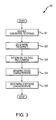
- FIG. 3 is a flowchart 300 of a method for determining a stiffness parameter (K) of a flow meter according to an embodiment of the invention.
- a vibrational response is received from the flow meter.
- the vibrational response is a response of the flow meter to a vibration at a substantially resonant frequency.
- the vibration can be continuous or intermittent.
- a flow material can be flowing through the meter assembly 10 or can be static.
- a frequency of the vibrational response is determined.
- the frequency ⁇ 0 can be determined from the vibrational response by any method, process, or hardware.
- step 303 the voltage (V or V EMF ) of the vibrational response is determined, along with the drive current (I).
- the voltage and drive current can be obtained from an unprocessed or a conditioned vibrational response.
- a damping characteristic of the flow meter is measured.
- the damping characteristic can be measured by allowing the vibrational response of the flow meter to decay down to a vibrational target while measuring the decay characteristic. This decaying action can be performed in several ways.
- the drive signal amplitude can be reduced, the driver 180 can actually perform braking of the meter assembly 10 (in appropriate flow meters), or the driver 180 can be merely unpowered until the target is reached.
- the vibrational target comprises a reduced level in a drive setpoint. For example, if the drive setpoint is currently at 3.4 mV/Hz, then for the damping measurement the drive setpoint can be reduced to a lower value, such as 2.5 mV/Hz, for example. In this manner, the meter electronics 20 can let the meter assembly 10 simply coast until the vibrational response substantially matches this new drive target.
- the stiffness parameter (K) is determined from the frequency, the voltage, the drive current, and the decay characteristic ( ⁇ ).
- the stiffness parameter (K) can be determined according to equation (9), above.
- the method can also determine and track a damping parameter (C) and a mass parameter (M).
- the method 300 can be iteratively, periodically, or randomly performed.
- the method 300 can be performed at predetermined landmarks, such as at a predetermined hours of operation, upon a change in flow material, etc.
- FIG. 4 is a flowchart 400 of a method for determining a stiffness change ( ⁇ K) in a flow meter according to an embodiment of the invention.
- a vibrational response is received from the flow meter, as previously discussed.
- step 402 a frequency of the vibrational response is determined, as previously discussed.
- step 403 the voltage and drive current of the vibrational response are determined, as previously discussed.
- step 404 the decay characteristic ( ⁇ ) of the flow meter is measured, as previously discussed.
- the stiffness parameter (K) is determined from the frequency, the voltage, the drive current, and the decay characteristic ( ⁇ ), as previously discussed.
- a second vibrational response is received at a second time instance t 2 .
- the second vibrational response is generated from a vibration of the meter assembly 10 at time t 2 .
- a second stiffness characteristic K 2 is generated from the second vibrational response.
- the second stiffness characteristic K 2 can be generated using steps 401 through 405, for example.
- the second stiffness characteristic K 2 is compared to the stiffness parameter (K).
- the comparison comprises a comparison of stiffness characteristics that are obtained at different times in order to detect a stiffness change ( ⁇ K).
- any stiffness change ( ⁇ K) between K 2 and K is determined.
- the stiffness change determination can employ any manner of statistical or mathematical method for determining a significant change in stiffness.
- the stiffness change ( ⁇ K) can be stored for future use and/or can be transmitted to a remote location.
- the stiffness change ( ⁇ K) can trigger an alarm condition in the meter electronics 20.
- the stiffness change ( ⁇ K) in one embodiment is first compared to the tolerance 224. If the stiffness change ( ⁇ K) exceeds the tolerance 224, then an error condition is determined.
- the method can also determine and track a damping parameter (C) and a mass parameter (M).
- the method 400 can be iteratively, periodically, or randomly performed.
- the method 400 can be performed at predetermined landmarks, such as at a predetermined hours of operation, upon a change in flow material, etc.
- FIG. 5 shows the meter electronics 20 according to another embodiment of the invention.
- the meter electronics 20 in this embodiment can include the interface 201, the processing system 203, and the storage system 204, as previously discussed.
- the meter electronics 20 receives three or more vibrational responses 505, such as from the meter assembly 10, for example.
- the meter electronics 20 processes the three or more vibrational responses 505 in order to obtain flow characteristics of the flow material flowing through the meter assembly 10.
- the three or more vibrational responses 505 are also processed in order to determine a stiffness parameter (K) of the meter assembly 10.
- the meter electronics 20 can further determine a damping parameter (C) and a mass parameter (M) from the three or more vibrational responses 505.
- K stiffness parameter
- M mass parameter
- the storage system 204 can store processing routines, such as the stiffness routine 506.
- the storage system 204 can store received data, such as the vibrational responses 505.
- the storage system 204 can store pre-programmed or user-entered values, such as the stiffness tolerance 516, the damping tolerance 517, and the mass tolerance 518.
- the storage system 204 can store working values, such as the pole ( ⁇ ) 508 and the residue (R) 509.
- the storage system 204 can store determined final values, such as the stiffness (K) 510, the damping (C) 511, and the mass (M) 512.
- the storage system 204 can store comparison values generated and operated on over periods of time, such as a second stiffness (K 2 ) 520, a second damping (C 2 ) 521, a second mass (M 2 ) 522, a stiffness change ( ⁇ K) 530, a damping change ( ⁇ C) 531, and a mass change ( ⁇ M) 532.
- the stiffness change ( ⁇ K) 530 can comprise a change in the stiffness parameter (K) of the meter assembly 10 as measured over time.
- the stiffness change ( ⁇ K) 530 can be used to detect and determine physical changes to the meter assembly 10 over time, such as corrosion and erosion effects.
- the mass parameter (M) 512 of the meter assembly 10 can be measured and tracked over time and stored in a mass change ( ⁇ M) 532 and a damping parameter (C) 511 can be measured over time and stored in a damping change ( ⁇ C) 531.
- the mass change ( ⁇ M) 532 can indicate the presence of build-up of flow materials in the meter assembly 10 and the damping change ( ⁇ C) 531 can indicate changes in a flow tube, including material degradation, erosion and corrosion, cracking, etc.
- the meter electronics 20 receives three or more vibrational responses 505 and processes the vibrational responses 505 using the stiffness routine 506.
- the three or more vibrational responses 505 comprise five vibrational responses 505, as will be discussed below.
- the meter electronics 20 determines the pole ( ⁇ ) 508 and the residue (R) 509 from the vibrational responses 505.
- the pole ( ⁇ ) 508 and residue (R) 509 can comprise a first order pole and residue or can comprise a second order pole and residue.
- the meter electronics 20 determines the stiffness parameter (K) 510, the damping parameter (C) 511, and the mass parameter (M) 512 from the pole ( ⁇ ) 508 and the residue (R) 509.
- the meter electronics 20 can further determine a second stiffness (K 2 ) 520, can determine a stiffness change ( ⁇ K) 530 from the stiffness parameter (K) 510 and the second stiffness (K 2 ) 520, and can compare the stiffness change ( ⁇ K) 530 to a stiffness tolerance 516. If the stiffness change ( ⁇ K) 530 exceeds the stiffness tolerance 516, the meter electronics 20 can initiate any manner of error recordation and/or error processing routine. Likewise, the meter electronics 20 can further track the damping and mass parameters over time and can determine and record a second damping (C 2 ) 521 and a second mass (M 2 ), and a resulting damping change ( ⁇ C) 531 and mass change ( ⁇ M) 532. The damping change ( ⁇ C) 531 and the mass change ( ⁇ M) 532 can likewise be compared to a damping tolerance 517 and a mass tolerance 518.
- the invention can be illustrated with a mathematical model.
- the term ⁇ comprises a decay characteristic measurement obtained from the vibrational response, as previously discussed.
- x is the physical displacement distance of the vibration
- ⁇ is the velocity of the flowtube displacement
- ⁇ is the acceleration. This is commonly referred to as the MCK model.
- Equation (11) can be further manipulated into a transfer function form, while ignoring the initial conditions.
- the system parameters comprising the natural/resonant frequency ( ⁇ n ), the damped natural frequency ( ⁇ d ), and the decay characteristic ( ⁇ ) are defined by the pole.
- the stiffness parameter (K), the damping parameter (C), and the mass parameter (M) of the system can be derived from the pole and residue.
- M 1 2 ⁇ jR ⁇ ⁇ d
- K ⁇ n 2 ⁇ M
- C 2 ⁇ ⁇ ⁇ ⁇ n ⁇ M
- the stiffness parameter (K), the mass parameter (M), and the damping parameter (C) can be calculated based on a good estimate of the pole ( ⁇ ) and the residue (R).
- the pole and residue are estimated from the measured frequency response functions.
- the pole ( ⁇ ) and the residue (R) can be estimated using some manner of direct or iterative computational method.
- the H( ⁇ ) term is the measured frequency response function (FRF), obtained from the three or more vibrational responses.
- FRF measured frequency response function
- H is composed of a displacement output divided by a force input.
- the measured FRF i . e ., a ⁇ term
- Equation (21) can be further rearranged into a form that is easily solvable for the pole ( ⁇ ) and the residue (R).
- Equation (22) forms an over-determined system of equations. Equation (22) can be computationally solved in order to determine the pole ( ⁇ ) and the residue (R) from the velocity/force FRF ( ⁇ ).
- the terms H, R, and ⁇ , are complex.
- the forcing frequency ⁇ is 5 tones.
- the 5 tones in this embodiment comprise the drive frequency and 2 tones above the drive frequency and 2 tones below.
- the tones can be separated from the fundamental frequency by as little as 0.5-2 Hz.
- the forcing frequency ⁇ can comprise more tones or fewer tones, such as a drive frequency and 1 tone above and below.
- 5 tones strikes a good compromise between accuracy of the result and the processing time needed to obtain the result.
- Equation (23) can be solved in any number of ways.
- the equation is solved through a recursive least squares approach.
- the equation is solved through a pseudo-inverse technique.
- a standard Q-R decomposition technique can be used. The Q-R decomposition technique is discussed in Modern Control Theory, William Brogan, copyright 1991, Prentice Hall, pp. 222-224, 168-172 .
- the stiffness parameter (K), along with the damping parameter (C) and the mass parameter (M), can be tracked over time. For example, statistical techniques can be used to determine any changes in the stiffness parameter (K) over time ( i . e ., a stiffness change ( ⁇ K)). A statistical change in the stiffness parameter (K) can indicate that the FCF for the particular flow meter has changed.
- the invention provides a stiffness parameter (K) that does not rely on stored or recalled calibration density values. This is in contrast to the prior art, where a known flow material is used in a factory calibration operation to obtain a density standard that can be used for all future calibration operations.
- the invention provides a stiffness parameter (K) that is obtained solely from vibrational responses of the flow meter.
- the invention provides a stiffness detection/calibration process without the need for a factory calibration process.
- FIG. 6 is a flowchart 600 of a method for determining a stiffness parameter (K) of a flow meter according to an embodiment of the invention.
- K stiffness parameter
- step 601 three or more vibrational responses are received.
- the three or more vibrational responses can be received from the flow meter.
- the three or more vibrational responses can include a substantially fundamental frequency response and two or more non-fundamental frequency responses.
- one tone above the fundamental frequency response is received and one tone below the fundamental frequency response is received.
- two or more tones above the fundamental frequency response are received and two ore more tones below the fundamental frequency response are received.
- the tones are substantially equidistantly spaced above and below the fundamental frequency response.
- the tones are not equidistantly spaced.
- a first order pole-residue frequency response is generated from the three or more vibrational responses.
- the first order pole-residue frequency response takes the form given in equation (23).
- the mass parameter (M) is determined from the first order pole-residue frequency response.
- the mass parameter (M) is determined by determining the first order pole ( ⁇ ) and the first order residue (R) of the vibrational responses.
- the natural frequency ⁇ n , the damped natural frequency ⁇ d , and the decay characteristic ( ⁇ ) are determined from the first order pole ( ⁇ ) and residue (R).
- the damped natural frequency ⁇ d , the residue (R), and the imaginary term (j) are plugged into equation (17) in order to obtain the mass parameter (M).
- step 604 the stiffness parameter (K) is determined from the solution of equation (18).
- the solution employs the natural frequency ⁇ n and the determined mass parameter (M) from step 603 are plugged into equation (18) in order to obtain the stiffness parameter (K).
- step 605 the damping parameter (C) is determined from the solution of equation (19).
- the solution employs the decay characteristic ( ⁇ ), the natural frequency ⁇ n , and the determined mass parameter (M).
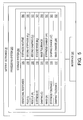
- FIG. 7 shows an implementation of the pole ( ⁇ ) and residue (R) solutions according to an embodiment of the invention.
- the implementation follows equation (23).
- the FRF inputs are at the left of the diagram. These FRF inputs are the five frequencies at which FRF coefficients are calculated in this embodiment (four test signal frequencies and the drive frequency).
- the FRF_L and FRF_R inputs are the driver-pickoff complex FRF coefficients calculated at those frequencies, corresponding to ⁇ LPO and ⁇ RPO in equation (23).
- the FRF coefficients are passed into the B input of the QR solver block 701.
- the A matrix for the QR solver block 701 is formed from the FRF coefficients divided by j ⁇ on a term-by-term basis and comprises columns of 1's and 0's to conform with equation (23).
- the matrix is reshaped into the proper [10x3] complex dimensions and passed into the A input of the QR solver block 701.
- the x vector output of the QR solver block 701 comprises the left and right residues R L and R R and the pole ⁇ . These outputs are passed out of the QR block 701 for processing in order to generate the system parameters.
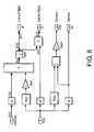
- FIG. 8 is a block diagram showing the calculation of the M, C, and K system parameters according to an embodiment of the invention.
- the implementation determines the M, C, and K system parameters from the pole and residue estimates per equations (14-16) and equations (17-19).
- the residues are purely imaginary for a real normal modal model. However, there will always be some real part due to noise in the measurement data and due to model-fitting numerical precision issues. Therefore, the absolute value of the residue is used, which has a similar effect as dividing by j per equation (17).
- the mass and stiffness are calculated using the pole and residue per equations (17-18). Note that there is a "Left" and "Right" mass and stiffness, i .
- the mass and stiffness calculated from the FRFs of the LPO/Driver and the RPO/Driver may differ from right to left due to asymmetries in the coils and magnets and in the structure itself. Changes in the differences or the difference ratios indicate a non-uniform change in mass or stiffness and can be exploited to give additional diagnostic information about changes to the FCF or the integrity of the flow meter.
- ⁇ n makes a good quality check for the closed loop drive system. If the drive is indeed operating at resonance, the drive frequency should agree to within a few milliHertz to the natural frequency estimate. If the difference in more than a few milliHertz, a warning flag can be set, indicating that the drive system is not operating properly or that the current stiffness estimate is suspect.
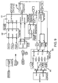
- FIG. 9 shows an overall FRF-based stiffness estimation system according to an embodiment of the invention.
- the stiffness estimation subsystem There are seven distinct inputs to the stiffness estimation subsystem, indicated by pentagons that are signal sources (five on the top left, and two on the far right).
- the "RawDrive” and “RawPOs” inputs are the raw readings of the pickoff voltages and the drive current. These signals are down-sampled to 2 kHz by decimation, for example, and are then fed into the FRF coefficient estimation subsystem.
- the "CmdmA” input is the commanded current that is taken from the output of a corresponding digital drive system.
- the "StiffnessEnable” estimate is a logical input, allowing the digital drive system to control when the FCF validation algorithm is active.
- the "freq” input is the drive frequency, as estimated by the digital drive system. It is input to the test signal generator subsystem and the stiffness calculation subsystem.
- the FRF Stiffness calculation block 902 outputs the system parameter estimates M & K Lft and Rt as well as Zeta and FreqEst. These are the primary diagnostic outputs used in FCF validation.
- the figure also shows a freq diff Warn block 903 and a freq diff Error block 904 that implement the drive quality check discussed above by comparing the drive frequency to the estimated natural frequency.
- the CL Input Select block 906 and the CL Output Correction block 907 implement the calibration algorithm.
- the calibration process uses the "Test Signal FRF" block 901 to calculate the frequency response function of the actual (RawDrive) current to the commanded current (CmdmA) at one state of the controlling logic.
- the FRF between the raw POs and the commanded current is calculated and corrected by the raw to commanded current FRF coefficients to give the FRFs used for further processing.
- the FRF stiffness estimation algorithm outputs the "TestSignal" output at the center left of the diagram of the figure. This test signal output contains excitation at the four test frequencies that are added to the drive command immediately before output. These test signals are added to the digital drive signal when FCF validation is enabled.
- the logic is such that when the FCF validation is off, the digital drive signal passes right through a switch or other device, where it is upsampled from its base rate (typically 4 kHz) by the interpolation filter to the appropriate output rate, typically 8 kHz.
- the test signals upsampled from 2 to 4 kHz, are added to the digital drive signal.
- the drive signal then consists of the closed loop drive frequency signal and the 4 test tones, all of which then go through the upsample filter.
- the FCF validation procedure is desirably transparent to the drive system.
- the test signals are removed from the pickoffs to ensure a good frequency and amplitude estimate for the closed loop drive. This is done with a set of notch filters tuned to the exact frequencies of the test signals.
- the pole-residue approach can employ a second-order pole-residue frequency response function in order to achieve a better result.
- a second order pole-residue approach provides a truer fit to the real data than a first order pole-residue approach.
- the trade-off is a greater numerical complexity and increased processing time.
- the MCK embodiment of the stiffness estimation begins with a simple second order system model, as shown in equation (24), below. Since the pickoffs on the flow meter measure velocity, not position, the equation is differentiated and then evaluated at a particular frequency ⁇ .
- a driver-pickoff FRF at one particular frequency ⁇ 1 is sufficient to solve the equations and determine the parameters M, C, and K. This is particularly useful; when FRFs are taken at multiple frequencies the least-squares fit to the data is simply the average of the individual estimates of each coefficient. This is a good deal simpler than the pseudo inverse that typically would have to be performed.
- the restriction that ⁇ n precludes the use of the resonant drive FRF in the solution for K or M. This is not particularly surprising since the height of a peak at a resonance is determined solely by the damping.
- One potential shortcoming of this approach is that the parameters estimated from left and right pickoff data are necessarily independent of each other. This is in contrast to the pole-residue method, where some benefit is gained by restricting the left and right pickoffs to estimate the same pole, despite their differences in amplitude.
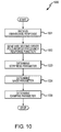
- FIG. 10 is a flowchart 1000 of a method for determining a stiffness parameter (K) of a flow meter according to an embodiment of the invention.
- K stiffness parameter
- a second order pole-residue frequency response is generated from the three or more vibrational responses.
- the second order pole-residue frequency response takes the form given in equation (24).
- the stiffness parameter (K) is determined from the solution of equation (29).
- the solution employs the natural frequency ⁇ n , the one or more frequency tones ⁇ , the imaginary portion of the FRF ( i . e ., an imaginary component of ⁇ ( ⁇ )), and an amplitude of the FRF ( i . e ., the absolute value of ⁇ ( ⁇ )).
- step 1004 the mass parameter (M) is determined from the second order pole-residue frequency response.
- the mass parameter (M) is determined from the solution of equation (29) and is obtained using the stiffness parameter (K) and the natural frequency ⁇ n .
- the damping parameter (C) is determined from the second order pole-residue frequency response.
- the damping parameter (C) is determined from the solution of equation (29) and is obtained using the one or more frequency tones ⁇ , the real portion of the FRF ( i . e ., a real component of ⁇ ( ⁇ )), and an amplitude of the FRF ( i . e ., the absolute value of ⁇ ( ⁇ )).
- FIG. 11 shows the implementation of the M, C, and K solutions for the second order pole-residue response from equations (29) according to an embodiment of the invention.
- the inputs appear as oval input ports at the left of the diagram.
- the drive frequency FRF is discarded by the selector blocks, since it cannot be used in the M and K solutions as described earlier.
- the solution for C is the same form as the derived solution in equations (29), and M is directly computed from the solution for K. Note the averaging operation that is applied to each coefficient estimate. This averaging results in solutions that are least-squares fits to the input data.
- the decay characteristic ( ⁇ ) is considered a more useful parameter than the damping parameter C. Therefore, the mass M, stiffness K, and decay characteristic ( ⁇ )are the outputs of the measurement.
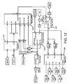
- FIG. 12 shows the overall FRF-based stiffness estimation system according to an embodiment of the invention.
- the "RawDrive” and “RawPOs” inputs are the raw readings from the pickoffs and the drive current. These are down sampled to 2 kHz by the Decimator block 1201 and then fed into the FRF coefficient estimation subsystem.
- the "DriveDemod” input is a sine and cosine signal at the drive frequency that is taken from a digital drive system. These signals are combined with sinusoids generated at the test frequencies and fed into the FRF coefficient estimation subsystem as bases for demodulation.
- the "StiffnessEnable” estimate is a logical input, allowing the digital drive system to control when the stiffness estimation algorithm is active.
- the “freq” input is the drive frequency, as estimated by the digital drive system. It is input to the test signal generation block 1204 and the stiffness calculation block 1206.
- the “Temp” input is the temperature read from the flow meter that is inputted into the temperature correction block 1207.
- the FRF stiffness estimation algorithm outputs the system parameter estimates, as well as the "TestSignal” output at the far left side of the diagram. This test signal output contains excitation at the four test frequencies that are to be added to the driver command.
- test signals are added to the drive command immediately before output to a driver device.
- FCF validation procedure it is necessary to remove the test signals from the pickoffs. This is done in one embodiment with a set of notch filters tuned to the exact frequencies of the test signals.
- the Test Signal FRF block 1208 of FIG. 11 performs demodulations.
- the pickoff and drive signals are demodulated at each of five input frequencies, the four generated test signal frequencies, and the drive frequency. After doing the complex demodulation using the sine and cosine bases, the real and imaginary components of each signal are decimated down to a lower frequency and low pass filtered to 0.4 Hz. It is necessary that these signals be uncontaminated in this region, as any spectral component within 0.4 Hz of the test signal will not be suppressed and will appear in the output.
- the complex coefficients for the pickoffs and drive current at each frequency are then used to estimate the FRF at that frequency.
- the power spectra are averaged over a number of samples, and the lower-rate FRF estimate is output.
- the meter electronics and methods according to the invention can be employed according to any of the embodiments in order to provide several advantages, if desired.
- the invention provides a stiffness parameter (K) that is substantially related to a flowtube stiffness of the flow meter.
- the invention provides a stiffness parameter (K) that does not rely on stored or recalled calibration values for generation.
- the invention provides a stiffness parameter (K) that is obtained solely from a vibrational response of the flow meter.
- the invention provides a mass parameter (M) and a damping parameter (C) from the vibrational response.
- the invention provides a stiffness detection/calibration process without the need for a factory calibration process.
- the invention can perform a stiffness/FCF calibration process in the field.
- the invention can perform a stiffness/FCF calibration process at any time.
- the invention can perform a stiffness/FCF calibration process without the need for a calibration test rig and/or known flow materials.
- the invention can perform stiffness/FCF calibration processes that determine changes in stiffness of the flow meter over time.
Landscapes
- Physics & Mathematics (AREA)
- General Physics & Mathematics (AREA)
- Fluid Mechanics (AREA)
- Biochemistry (AREA)
- Health & Medical Sciences (AREA)
- Life Sciences & Earth Sciences (AREA)
- Chemical & Material Sciences (AREA)
- Analytical Chemistry (AREA)
- General Health & Medical Sciences (AREA)
- Immunology (AREA)
- Pathology (AREA)
- Signal Processing (AREA)
- Engineering & Computer Science (AREA)
- Measuring Volume Flow (AREA)
Applications Claiming Priority (2)
| Application Number | Priority Date | Filing Date | Title |
|---|---|---|---|
| PCT/US2005/033285 WO2007040468A1 (fr) | 2005-09-19 | 2005-09-19 | Electronique de mesure et procedes permettant de verifier des diagnostics pour un debitmetre |
| EP05805681.3A EP1949046B1 (fr) | 2005-09-19 | 2005-09-19 | Electronique de mesure et procede permettant de verifier des diagnostics pour un debitmetre |
Related Parent Applications (2)
| Application Number | Title | Priority Date | Filing Date |
|---|---|---|---|
| EP05805681.3A Division-Into EP1949046B1 (fr) | 2005-09-19 | 2005-09-19 | Electronique de mesure et procede permettant de verifier des diagnostics pour un debitmetre |
| EP05805681.3A Division EP1949046B1 (fr) | 2005-09-19 | 2005-09-19 | Electronique de mesure et procede permettant de verifier des diagnostics pour un debitmetre |
Publications (3)
| Publication Number | Publication Date |
|---|---|
| EP2103913A2 true EP2103913A2 (fr) | 2009-09-23 |
| EP2103913A3 EP2103913A3 (fr) | 2009-10-07 |
| EP2103913B1 EP2103913B1 (fr) | 2016-11-30 |
Family
ID=36294845
Family Applications (2)
| Application Number | Title | Priority Date | Filing Date |
|---|---|---|---|
| EP05805681.3A Expired - Lifetime EP1949046B1 (fr) | 2005-09-19 | 2005-09-19 | Electronique de mesure et procede permettant de verifier des diagnostics pour un debitmetre |
| EP09165263.6A Expired - Lifetime EP2103913B1 (fr) | 2005-09-19 | 2005-09-19 | Électronique de compteur et procédé pour le diagnostic de vérification de débitmètre de Coriolis |
Family Applications Before (1)
| Application Number | Title | Priority Date | Filing Date |
|---|---|---|---|
| EP05805681.3A Expired - Lifetime EP1949046B1 (fr) | 2005-09-19 | 2005-09-19 | Electronique de mesure et procede permettant de verifier des diagnostics pour un debitmetre |
Country Status (10)
| Country | Link |
|---|---|
| US (2) | US7865318B2 (fr) |
| EP (2) | EP1949046B1 (fr) |
| JP (1) | JP4836210B2 (fr) |
| KR (3) | KR20130025951A (fr) |
| CN (1) | CN101268340B (fr) |
| AR (2) | AR055637A1 (fr) |
| AU (1) | AU2005336982B2 (fr) |
| BR (2) | BRPI0520555B1 (fr) |
| CA (1) | CA2622976C (fr) |
| WO (1) | WO2007040468A1 (fr) |
Cited By (2)
| Publication number | Priority date | Publication date | Assignee | Title |
|---|---|---|---|---|
| EP3837502B1 (fr) * | 2018-08-13 | 2023-06-14 | Micro Motion, Inc. | Détermination d'un amortissement d'un ensemble compteur |
| DE102023101930A1 (de) * | 2022-12-02 | 2024-06-13 | Endress+Hauser Flowtec Ag | Verfahren zum Überprüfen und/oder (Wieder-)Inbetriebnehmen eines modularen Meßsystems |
Families Citing this family (66)
| Publication number | Priority date | Publication date | Assignee | Title |
|---|---|---|---|---|
| BRPI0520555B1 (pt) * | 2005-09-19 | 2017-11-14 | Micro Motion, Inc. | Electronic meter apparatus and method for determining a rigidity parameter of a flow meter |
| US7689372B2 (en) * | 2006-12-13 | 2010-03-30 | Abb Patent Gmbh | Process for operating a measurement device of the vibration type |
| JP4909124B2 (ja) * | 2007-03-02 | 2012-04-04 | キヤノン株式会社 | 情報処理装置、情報処理方法及びコンピュータプログラム |
| US8278942B2 (en) | 2008-04-01 | 2012-10-02 | Phase Dynamics, Inc. | Self-checking analyzer method and system using reflected power/insertion loss |
| DE102008050115A1 (de) * | 2008-10-06 | 2010-04-08 | Endress + Hauser Flowtec Ag | In-Line-Meßgerät |
| DE102008050113A1 (de) | 2008-10-06 | 2010-04-08 | Endress + Hauser Flowtec Ag | In-Line-Meßgerät |
| DE102008050116A1 (de) | 2008-10-06 | 2010-04-08 | Endress + Hauser Flowtec Ag | In-Line-Meßgerät |
| DE102009002942A1 (de) | 2009-05-08 | 2010-11-11 | Endress + Hauser Flowtec Ag | Verfahren zum Bestimmen einer Messrohr-Rohrwanddicke eines Coriolis-Durchflussmessgerätes |
| JP4911219B2 (ja) * | 2009-11-10 | 2012-04-04 | 横河電機株式会社 | コリオリ質量流量計 |
| DE102009046839A1 (de) | 2009-11-18 | 2011-05-19 | Endress + Hauser Flowtec Ag | Meßsystem mit einer zwei parallel durchströmte Meßrohre aufweisenden Rohranordnung sowie Verfahren zu deren Überwachung |
| WO2011080172A1 (fr) | 2009-12-31 | 2011-07-07 | Endress+Hauser Flowtec Ag | Système de mesure comportant un convertisseur de mesure de type vibrant |
| DE102010000761A1 (de) | 2010-01-11 | 2011-07-28 | Endress + Hauser Flowtec Ag | Meßsystem mit einem Meßwandler vom Vibrationstyp |
| CN101750136B (zh) * | 2009-12-31 | 2012-07-25 | 北京航空航天大学 | 一种基于管内磁场仿真数值计算的电磁流量计干标定方法 |
| JP4952820B2 (ja) * | 2010-05-13 | 2012-06-13 | 横河電機株式会社 | コリオリ流量計 |
| WO2012051561A2 (fr) * | 2010-10-14 | 2012-04-19 | Inova Ltd. | Filtrage de données sismiques basé sur un modèle terrestre couplé à un vibrateur |
| DE102011006919A1 (de) | 2011-04-07 | 2012-10-11 | Endress + Hauser Flowtec Ag | Verfahren zum Trimmen eines Rohrs |
| DE102011006971A1 (de) | 2011-04-07 | 2012-10-11 | Endress + Hauser Flowtec Ag | Meßwandler vom Vibrationstyp sowie Verfahren zu dessen Herstellung |
| DE102011006997A1 (de) | 2011-04-07 | 2012-10-11 | Endress + Hauser Flowtec Ag | Frequenzabgleichsverfahren für eine Rohranordnung |
| EP2732249B1 (fr) * | 2011-07-13 | 2020-03-18 | Micro Motion, Inc. | Vibromètre et procédé permettant de déterminer une fréquence résonante |
| DE102011086395A1 (de) * | 2011-11-15 | 2013-05-16 | Endress + Hauser Flowtec Ag | Verfahren zum Überwachen der Schwingungseigenschaften in einem Coriolis-Durchflussmessgerät |
| KR101827459B1 (ko) | 2012-01-10 | 2018-02-08 | 마이크로 모우션, 인코포레이티드 | 현장 정비 장치 및 진동 유량계에서 프로세싱 시스템 교체를 용이하게 하는 방법 |
| CN102589659B (zh) * | 2012-03-16 | 2014-05-28 | 西安东风机电有限公司 | 一种科里奥利质量流量计现场测量系统及其检测方法 |
| WO2013149817A1 (fr) | 2012-04-03 | 2013-10-10 | Endress+Hauser Flowtec Ag | Transducteur de type vibratoire |
| DE102012102947B4 (de) | 2012-04-03 | 2023-12-21 | Endress + Hauser Flowtec Ag | Meßwandler vom Vibrationstyp |
| US9658097B2 (en) | 2012-05-11 | 2017-05-23 | Bristol, Inc. | Systems and methods to initiate a verification test within a flow meter via a flow computer |
| DE102012011934B4 (de) * | 2012-06-18 | 2014-07-10 | Krohne Messtechnik Gmbh | Verfahren zum Betreiben eines Resonazmesssystems und diesbezügliche Resonanzmesssystem |
| BR112015004054B1 (pt) * | 2012-08-28 | 2021-05-04 | Halliburton Energy Services, Inc | método para determinar um fator geométrico de um sensor |
| BR112015011862B1 (pt) | 2012-11-29 | 2020-05-26 | Micro Motion, Inc | Método para determinar uma rigidez de modo lateral de um ou mais tubos de fluido em um medidor vibratório, eletrônica de medidor , e , medidor vibratório |
| US10215677B2 (en) * | 2013-04-18 | 2019-02-26 | Micro Motion, Inc. | Verification of a meter sensor for a vibratory meter |
| DE102013106155A1 (de) | 2013-06-13 | 2014-12-18 | Endress + Hauser Flowtec Ag | Meßsystem mit einem Druckgerät sowie Verfahren zur Überwachung und/oder Überprüfung eines solchen Druckgeräts |
| DE102013106157A1 (de) | 2013-06-13 | 2014-12-18 | Endress + Hauser Flowtec Ag | Meßsystem mit einem Druckgerät sowie Verfahren zur Überwachung und/oder Überprüfung eines solchen Druckgeräts |
| EP3008428B1 (fr) * | 2013-06-14 | 2021-02-24 | Micro Motion, Inc. | Debitmetre vibratoire et procede de verification de dispositif de mesure |
| CA3088354C (fr) * | 2014-01-24 | 2023-08-29 | Micro Motion, Inc. | Debitmetre vibratoire et procedes et diagnostics pour la verification du compteur |
| MX360511B (es) * | 2014-10-21 | 2018-11-07 | Micro Motion Inc | Aparato para aplicar un algoritmo de variable cero en un medidor de flujo vibratorio y metodo relacionado. |
| US9689736B2 (en) * | 2014-10-31 | 2017-06-27 | Invensys Systems, Inc. | Method to provide a quality measure for meter verification results |
| WO2017019012A1 (fr) * | 2015-07-27 | 2017-02-02 | Micro Motion, Inc. | Tonalités de test de débitmètre vibratoire sans temps de mise en route |
| CN108139261B (zh) * | 2015-10-21 | 2020-10-20 | 高准公司 | 原地换能器校准 |
| EP3258239A1 (fr) * | 2016-06-13 | 2017-12-20 | INL - International Iberian Nanotechnology Laboratory | Procédé de validation d'un résonateur |
| EP3488193B1 (fr) * | 2016-07-20 | 2021-11-17 | Micro Motion, Inc. | Procédé et électronique de mesure pour effectuer une compensation de température d'une amplitude tonale de test pendant une vérification de débitmètre |
| JP6876798B2 (ja) * | 2016-11-30 | 2021-05-26 | マイクロ モーション インコーポレイテッド | メータ検証に使用されるテストトーンの温度補償 |
| BR112019024696B1 (pt) * | 2017-06-14 | 2022-11-01 | Micro Motion, Inc | Eletrônica de medidor, e, método de filtrar com um filtro rejeita-faixa um sinal de sensor em um medidor vibratório |
| EP3638991B1 (fr) * | 2017-06-14 | 2021-08-04 | Micro Motion, Inc. | Espacements de fréquence pour empêcher une interférence de signal de distorsion d'intermodulation |
| WO2019032098A1 (fr) * | 2017-08-08 | 2019-02-14 | Micro Motion, Inc. | Dispositifs et procédés d'élimination de totalisations fausses d'un débitmètre |
| JP7012144B2 (ja) * | 2017-08-30 | 2022-01-27 | マイクロ モーション インコーポレイテッド | 振動計の変化の検出及び識別 |
| JP2020532716A (ja) * | 2017-08-30 | 2020-11-12 | マイクロ モーション インコーポレイテッド | 振動計の基準トレース可能な検証 |
| DE102017131199A1 (de) | 2017-12-22 | 2019-06-27 | Endress + Hauser Flowtec Ag | Coriolis-Massendurchfluß-Meßgerät |
| JP7024466B2 (ja) * | 2018-02-05 | 2022-02-24 | 横河電機株式会社 | コリオリ流量計、時期予測システム、及び時期予測方法 |
| RU2766256C1 (ru) * | 2018-07-30 | 2022-02-10 | Майкро Моушн, Инк. | Электронный измеритель и способы верификационной диагностики расходомера |
| BR112021001408B1 (pt) * | 2018-08-13 | 2023-10-10 | Micro Motion, Inc | Eletrônica de medidor, e, método para determinar uma característica de declínio de um conjunto medidor de um medidor de fluxo |
| RU2759828C1 (ru) * | 2018-08-13 | 2021-11-18 | Майкро Моушн, Инк. | Способ определения того, когда проверять коэффициент жесткости расходомера |
| CN112805541B (zh) * | 2018-10-08 | 2024-08-20 | 高准有限公司 | 清洁和检测振动测量仪的清洁状况 |
| DE102018133117A1 (de) | 2018-12-20 | 2020-06-25 | Endress+Hauser Flowtec Ag | Coriolis-Massendurchfluß-Meßgerät |
| EP3899447B1 (fr) | 2018-12-20 | 2023-09-20 | Endress + Hauser Flowtec AG | Débitmètre massique à effet coriolis |
| US12174212B2 (en) | 2018-12-20 | 2024-12-24 | Endress+Hauser Flowtec Ag | Coriolis mass flow meter |
| EP3899448B1 (fr) | 2018-12-21 | 2024-03-27 | Endress + Hauser Flowtec AG | Débitmètre massique à effet coriolis muni d'un détecteur de champ magnétique |
| DE102019133610A1 (de) | 2019-12-09 | 2021-06-10 | Endress + Hauser Flowtec Ag | Vibronisches Meßsystem zum Messen eines Massestroms eines fluiden Meßstoff |
| WO2021185610A1 (fr) * | 2020-03-20 | 2021-09-23 | Endress+Hauser Flowtec Ag | Procédé d'utilisation d'un dispositif de mesure à effet coriolis |
| DE102020111127A1 (de) | 2020-04-23 | 2021-10-28 | Endress+Hauser Flowtec Ag | Verfahren zum Überwachen eines Coriolis-Massedurchflussmessaufnehmers |
| US20210333219A1 (en) * | 2020-04-27 | 2021-10-28 | Mpi Corporation | Method of determining distance between probe and wafer held by wafer probe station |
| US20230341248A1 (en) * | 2020-07-14 | 2023-10-26 | Micro Motion, Inc. | Using a stiffness measurement to compensate a fluid property measurement |
| DE102020127382A1 (de) | 2020-10-16 | 2022-04-21 | Endress+Hauser Flowtec Ag | Verfahren zum Überprüfen eines vibronischen Meßsystems |
| DE102020132949B4 (de) * | 2020-12-10 | 2026-02-05 | Endress+Hauser Flowtec Ag | Verfahren zum Identifizieren von Belägen in einer Prozessanlage mit einem Coriolis Massedurchflussmessaufnehmer |
| DE102020133850A1 (de) | 2020-12-16 | 2022-06-23 | Endress+Hauser Flowtec Ag | Verfahren zum Betreiben eines Durchfluss-Messgeräts und Messsystem |
| JP7601041B2 (ja) * | 2022-03-24 | 2024-12-17 | 横河電機株式会社 | 診断装置、診断方法および診断プログラム |
| DE102022112523A1 (de) | 2022-05-18 | 2023-11-23 | Endress+Hauser Flowtec Ag | Vibronisches Meßsystem |
| DE102022116111A1 (de) | 2022-06-28 | 2023-12-28 | Endress+Hauser Flowtec Ag | Vibronisches Meßsystem |
Citations (4)
| Publication number | Priority date | Publication date | Assignee | Title |
|---|---|---|---|---|
| EP0816807A2 (fr) | 1996-03-11 | 1998-01-07 | The Foxboro Company | Méthode et dispositif pour la correction des facteurs de dégradation de la performance d'un débitmètre massique de Coriolis |
| US20030191598A1 (en) | 2001-08-29 | 2003-10-09 | Micro Motion, Inc. | Apparatus, methods and computer program products for generating mass flow calibration factors using a normal modal dynamic characterization of a material-contained conduit |
| WO2005040734A1 (fr) | 2003-09-29 | 2005-05-06 | Micro Motion, Inc. | Appareil de diagnostic et methodes pour un debitmetre de coriolis |
| WO2005050145A1 (fr) | 2003-10-22 | 2005-06-02 | Micro Motion, Inc. | Appareil et methodes de diagnostic pour un debitmetre-masse a effet de coriolis |
Family Cites Families (17)
| Publication number | Priority date | Publication date | Assignee | Title |
|---|---|---|---|---|
| ES2033001T3 (es) | 1987-06-12 | 1993-03-01 | Juerg Dual | Viscosimetro |
| JP2793699B2 (ja) * | 1990-06-20 | 1998-09-03 | トキコ株式会社 | 質量流量計 |
| US5347874A (en) * | 1993-01-25 | 1994-09-20 | Micro Motion, Incorporated | In-flow coriolis effect mass flowmeter |
| US5579243A (en) * | 1994-09-20 | 1996-11-26 | Lucent Technologies Inc. | Modal parameter estimation for stable filters |
| CN1074539C (zh) * | 1995-09-14 | 2001-11-07 | 株式会社椭圆 | 科里奥利氏流量计 |
| FR2754898B1 (fr) | 1996-10-18 | 2000-08-18 | Comex Technologies | Procede et dispositif pour la mesure de la quantite d'un depot susceptible de s'etre forme dans une canalisation de transport de fluide |
| US6092409A (en) | 1998-01-29 | 2000-07-25 | Micro Motion, Inc. | System for validating calibration of a coriolis flowmeter |
| US6360579B1 (en) | 1999-03-26 | 2002-03-26 | Micro Motion, Inc. | Flowmeter calibration system with statistical optimization technique |
| US6505131B1 (en) * | 1999-06-28 | 2003-01-07 | Micro Motion, Inc. | Multi-rate digital signal processor for signals from pick-offs on a vibrating conduit |
| US6347293B1 (en) | 1999-07-09 | 2002-02-12 | Micro Motion, Inc. | Self-characterizing vibrating conduit parameter sensors and methods of operation therefor |
| US6782333B2 (en) | 2002-05-31 | 2004-08-24 | Micro Motion, Inc. | Meter calibration system and apparatus |
| JP2004052516A (ja) | 2002-07-22 | 2004-02-19 | Daiyuki Mori | ピッキング防止カバー |
| US20050072234A1 (en) * | 2003-05-20 | 2005-04-07 | Weidong Zhu | System and method for detecting structural damage |
| CN100520313C (zh) * | 2004-06-22 | 2009-07-29 | 微动公司 | 用于检测流量计组件中残积物的计量电子装置和方法 |
| AU2005330018B2 (en) * | 2005-03-29 | 2010-12-16 | Micro Motion, Inc. | Coriolis flow meter and method for determining flow characteristics |
| BRPI0520555B1 (pt) * | 2005-09-19 | 2017-11-14 | Micro Motion, Inc. | Electronic meter apparatus and method for determining a rigidity parameter of a flow meter |
| US7774150B2 (en) * | 2005-10-03 | 2010-08-10 | Micro Motion, Inc. | Meter electronics and methods for determining one or more of a stiffness coefficient or a mass coefficient |
-
2005
- 2005-09-19 BR BRPI0520555-7A patent/BRPI0520555B1/pt active IP Right Grant
- 2005-09-19 CA CA2622976A patent/CA2622976C/fr not_active Expired - Lifetime
- 2005-09-19 KR KR1020137002282A patent/KR20130025951A/ko not_active Ceased
- 2005-09-19 KR KR1020107009164A patent/KR101165043B1/ko not_active Expired - Fee Related
- 2005-09-19 JP JP2008532197A patent/JP4836210B2/ja not_active Expired - Lifetime
- 2005-09-19 BR BR122017014865-6A patent/BR122017014865B1/pt active IP Right Grant
- 2005-09-19 US US12/066,434 patent/US7865318B2/en active Active
- 2005-09-19 EP EP05805681.3A patent/EP1949046B1/fr not_active Expired - Lifetime
- 2005-09-19 EP EP09165263.6A patent/EP2103913B1/fr not_active Expired - Lifetime
- 2005-09-19 AU AU2005336982A patent/AU2005336982B2/en not_active Ceased
- 2005-09-19 WO PCT/US2005/033285 patent/WO2007040468A1/fr not_active Ceased
- 2005-09-19 KR KR1020117022585A patent/KR20110110875A/ko not_active Ceased
- 2005-09-19 CN CN2005800516264A patent/CN101268340B/zh not_active Expired - Lifetime
-
2006
- 2006-09-18 AR ARP060104075A patent/AR055637A1/es active IP Right Grant
-
2010
- 2010-11-17 US US12/948,141 patent/US8280651B2/en not_active Expired - Fee Related
-
2012
- 2012-01-17 AR ARP120100156A patent/AR084877A2/es active IP Right Grant
Patent Citations (4)
| Publication number | Priority date | Publication date | Assignee | Title |
|---|---|---|---|---|
| EP0816807A2 (fr) | 1996-03-11 | 1998-01-07 | The Foxboro Company | Méthode et dispositif pour la correction des facteurs de dégradation de la performance d'un débitmètre massique de Coriolis |
| US20030191598A1 (en) | 2001-08-29 | 2003-10-09 | Micro Motion, Inc. | Apparatus, methods and computer program products for generating mass flow calibration factors using a normal modal dynamic characterization of a material-contained conduit |
| WO2005040734A1 (fr) | 2003-09-29 | 2005-05-06 | Micro Motion, Inc. | Appareil de diagnostic et methodes pour un debitmetre de coriolis |
| WO2005050145A1 (fr) | 2003-10-22 | 2005-06-02 | Micro Motion, Inc. | Appareil et methodes de diagnostic pour un debitmetre-masse a effet de coriolis |
Cited By (2)
| Publication number | Priority date | Publication date | Assignee | Title |
|---|---|---|---|---|
| EP3837502B1 (fr) * | 2018-08-13 | 2023-06-14 | Micro Motion, Inc. | Détermination d'un amortissement d'un ensemble compteur |
| DE102023101930A1 (de) * | 2022-12-02 | 2024-06-13 | Endress+Hauser Flowtec Ag | Verfahren zum Überprüfen und/oder (Wieder-)Inbetriebnehmen eines modularen Meßsystems |
Also Published As
| Publication number | Publication date |
|---|---|
| EP1949046A1 (fr) | 2008-07-30 |
| AR055637A1 (es) | 2007-08-29 |
| BRPI0520555A2 (pt) | 2009-05-12 |
| JP2009509163A (ja) | 2009-03-05 |
| AR084877A2 (es) | 2013-07-10 |
| US20080281535A1 (en) | 2008-11-13 |
| AU2005336982A1 (en) | 2007-04-12 |
| EP1949046B1 (fr) | 2016-12-14 |
| WO2007040468A1 (fr) | 2007-04-12 |
| CN101268340B (zh) | 2010-11-03 |
| KR20110110875A (ko) | 2011-10-07 |
| BRPI0520555B1 (pt) | 2017-11-14 |
| AU2005336982B2 (en) | 2011-03-17 |
| US8280651B2 (en) | 2012-10-02 |
| BR122017014865B1 (pt) | 2018-07-24 |
| EP2103913A3 (fr) | 2009-10-07 |
| CA2622976A1 (fr) | 2007-04-12 |
| CA2622976C (fr) | 2013-05-07 |
| US7865318B2 (en) | 2011-01-04 |
| EP2103913B1 (fr) | 2016-11-30 |
| KR101165043B1 (ko) | 2012-07-13 |
| CN101268340A (zh) | 2008-09-17 |
| KR20100061569A (ko) | 2010-06-07 |
| KR20130025951A (ko) | 2013-03-12 |
| JP4836210B2 (ja) | 2011-12-14 |
| US20110178738A1 (en) | 2011-07-21 |
| HK1125169A1 (en) | 2009-07-31 |
Similar Documents
| Publication | Publication Date | Title |
|---|---|---|
| EP2103913B1 (fr) | Électronique de compteur et procédé pour le diagnostic de vérification de débitmètre de Coriolis | |
| US12038317B2 (en) | Vibratory flowmeter and methods and diagnostics for meter verification | |
| EP3008428B1 (fr) | Debitmetre vibratoire et procede de verification de dispositif de mesure | |
| US10605647B2 (en) | Vibratory flowmeter test tones without ramp time | |
| CN101819056B (zh) | 用于流量计的校验诊断的仪表电子器件和方法 | |
| CA2774131C (fr) | Electronique de mesure et procedes permettant de verifier des diagnostics pour un debitmetre | |
| EP3830530B1 (fr) | Électronique de compteur et procédés de diagnostic de vérification d'un débitmètre | |
| RU2376558C1 (ru) | Измерительная электроника и способы для поверочной диагностики для расходомера | |
| KR20080049833A (ko) | 유량계에 대한 확인 진단을 위한 방법 및 전자 계측장치 | |
| HK1143633B (en) | Meter electronics and methods for verification diagnostics for a flow meter | |
| HK1125169B (en) | Meter electronics and methods for verification diagnostics for a flow meter | |
| HK1252847A1 (zh) | 无斜坡时间的振动式流量计测试音调 | |
| HK1252847B (zh) | 无斜坡时间的振动式流量计测试音调 | |
| HK1127398B (en) | A method and apparatus for estimating a process parameter of a material flowing through a vibrating conduit | |
| HK1127398A1 (en) | A method and apparatus for estimating a process parameter of a material flowing through a vibrating conduit |
Legal Events
| Date | Code | Title | Description |
|---|---|---|---|
| PUAI | Public reference made under article 153(3) epc to a published international application that has entered the european phase |
Free format text: ORIGINAL CODE: 0009012 |
|
| PUAL | Search report despatched |
Free format text: ORIGINAL CODE: 0009013 |
|
| 17P | Request for examination filed |
Effective date: 20090712 |
|
| AC | Divisional application: reference to earlier application |
Ref document number: 1949046 Country of ref document: EP Kind code of ref document: P |
|
| AK | Designated contracting states |
Kind code of ref document: A2 Designated state(s): AT BE BG CH CY CZ DE DK EE ES FI FR GB GR HU IE IS IT LI LT LU LV MC NL PL PT RO SE SI SK TR |
|
| AK | Designated contracting states |
Kind code of ref document: A3 Designated state(s): AT BE BG CH CY CZ DE DK EE ES FI FR GB GR HU IE IS IT LI LT LU LV MC NL PL PT RO SE SI SK TR |
|
| RTI1 | Title (correction) |
Free format text: METER ELECTRONICS AND METHODS FOR VERIFICATION DIAGNOSTICS FOR A CORIOLIS FLOW METER |
|
| 17Q | First examination report despatched |
Effective date: 20100113 |
|
| GRAP | Despatch of communication of intention to grant a patent |
Free format text: ORIGINAL CODE: EPIDOSNIGR1 |
|
| RIC1 | Information provided on ipc code assigned before grant |
Ipc: G01N 9/00 20060101ALI20160601BHEP Ipc: G01F 25/00 20060101ALI20160601BHEP Ipc: G01F 15/02 20060101ALI20160601BHEP Ipc: G01F 1/84 20060101AFI20160601BHEP |
|
| INTG | Intention to grant announced |
Effective date: 20160621 |
|
| GRAS | Grant fee paid |
Free format text: ORIGINAL CODE: EPIDOSNIGR3 |
|
| GRAA | (expected) grant |
Free format text: ORIGINAL CODE: 0009210 |
|
| AC | Divisional application: reference to earlier application |
Ref document number: 1949046 Country of ref document: EP Kind code of ref document: P |
|
| AK | Designated contracting states |
Kind code of ref document: B1 Designated state(s): AT BE BG CH CY CZ DE DK EE ES FI FR GB GR HU IE IS IT LI LT LU LV MC NL PL PT RO SE SI SK TR |
|
| REG | Reference to a national code |
Ref country code: GB Ref legal event code: FG4D Ref country code: CH Ref legal event code: EP |
|
| REG | Reference to a national code |
Ref country code: AT Ref legal event code: REF Ref document number: 850242 Country of ref document: AT Kind code of ref document: T Effective date: 20161215 |
|
| REG | Reference to a national code |
Ref country code: IE Ref legal event code: FG4D |
|
| REG | Reference to a national code |
Ref country code: DE Ref legal event code: R096 Ref document number: 602005050832 Country of ref document: DE |
|
| REG | Reference to a national code |
Ref country code: NL Ref legal event code: FP |
|
| PG25 | Lapsed in a contracting state [announced via postgrant information from national office to epo] |
Ref country code: LV Free format text: LAPSE BECAUSE OF FAILURE TO SUBMIT A TRANSLATION OF THE DESCRIPTION OR TO PAY THE FEE WITHIN THE PRESCRIBED TIME-LIMIT Effective date: 20161130 |
|
| REG | Reference to a national code |
Ref country code: CH Ref legal event code: NV Representative=s name: VOSSIUS AND PARTNER PATENTANWAELTE RECHTSANWAE, CH |
|
| REG | Reference to a national code |
Ref country code: LT Ref legal event code: MG4D |
|
| REG | Reference to a national code |
Ref country code: AT Ref legal event code: MK05 Ref document number: 850242 Country of ref document: AT Kind code of ref document: T Effective date: 20161130 |
|
| PG25 | Lapsed in a contracting state [announced via postgrant information from national office to epo] |
Ref country code: SE Free format text: LAPSE BECAUSE OF FAILURE TO SUBMIT A TRANSLATION OF THE DESCRIPTION OR TO PAY THE FEE WITHIN THE PRESCRIBED TIME-LIMIT Effective date: 20161130 Ref country code: LT Free format text: LAPSE BECAUSE OF FAILURE TO SUBMIT A TRANSLATION OF THE DESCRIPTION OR TO PAY THE FEE WITHIN THE PRESCRIBED TIME-LIMIT Effective date: 20161130 Ref country code: GR Free format text: LAPSE BECAUSE OF FAILURE TO SUBMIT A TRANSLATION OF THE DESCRIPTION OR TO PAY THE FEE WITHIN THE PRESCRIBED TIME-LIMIT Effective date: 20170301 |
|
| PG25 | Lapsed in a contracting state [announced via postgrant information from national office to epo] |
Ref country code: PL Free format text: LAPSE BECAUSE OF FAILURE TO SUBMIT A TRANSLATION OF THE DESCRIPTION OR TO PAY THE FEE WITHIN THE PRESCRIBED TIME-LIMIT Effective date: 20161130 Ref country code: PT Free format text: LAPSE BECAUSE OF FAILURE TO SUBMIT A TRANSLATION OF THE DESCRIPTION OR TO PAY THE FEE WITHIN THE PRESCRIBED TIME-LIMIT Effective date: 20170330 Ref country code: ES Free format text: LAPSE BECAUSE OF FAILURE TO SUBMIT A TRANSLATION OF THE DESCRIPTION OR TO PAY THE FEE WITHIN THE PRESCRIBED TIME-LIMIT Effective date: 20161130 Ref country code: AT Free format text: LAPSE BECAUSE OF FAILURE TO SUBMIT A TRANSLATION OF THE DESCRIPTION OR TO PAY THE FEE WITHIN THE PRESCRIBED TIME-LIMIT Effective date: 20161130 Ref country code: FI Free format text: LAPSE BECAUSE OF FAILURE TO SUBMIT A TRANSLATION OF THE DESCRIPTION OR TO PAY THE FEE WITHIN THE PRESCRIBED TIME-LIMIT Effective date: 20161130 |
|
| PG25 | Lapsed in a contracting state [announced via postgrant information from national office to epo] |
Ref country code: DK Free format text: LAPSE BECAUSE OF FAILURE TO SUBMIT A TRANSLATION OF THE DESCRIPTION OR TO PAY THE FEE WITHIN THE PRESCRIBED TIME-LIMIT Effective date: 20161130 Ref country code: SK Free format text: LAPSE BECAUSE OF FAILURE TO SUBMIT A TRANSLATION OF THE DESCRIPTION OR TO PAY THE FEE WITHIN THE PRESCRIBED TIME-LIMIT Effective date: 20161130 Ref country code: CZ Free format text: LAPSE BECAUSE OF FAILURE TO SUBMIT A TRANSLATION OF THE DESCRIPTION OR TO PAY THE FEE WITHIN THE PRESCRIBED TIME-LIMIT Effective date: 20161130 Ref country code: EE Free format text: LAPSE BECAUSE OF FAILURE TO SUBMIT A TRANSLATION OF THE DESCRIPTION OR TO PAY THE FEE WITHIN THE PRESCRIBED TIME-LIMIT Effective date: 20161130 Ref country code: RO Free format text: LAPSE BECAUSE OF FAILURE TO SUBMIT A TRANSLATION OF THE DESCRIPTION OR TO PAY THE FEE WITHIN THE PRESCRIBED TIME-LIMIT Effective date: 20161130 |
|
| PG25 | Lapsed in a contracting state [announced via postgrant information from national office to epo] |
Ref country code: BG Free format text: LAPSE BECAUSE OF FAILURE TO SUBMIT A TRANSLATION OF THE DESCRIPTION OR TO PAY THE FEE WITHIN THE PRESCRIBED TIME-LIMIT Effective date: 20170228 Ref country code: BE Free format text: LAPSE BECAUSE OF FAILURE TO SUBMIT A TRANSLATION OF THE DESCRIPTION OR TO PAY THE FEE WITHIN THE PRESCRIBED TIME-LIMIT Effective date: 20161130 |
|
| REG | Reference to a national code |
Ref country code: DE Ref legal event code: R097 Ref document number: 602005050832 Country of ref document: DE |
|
| REG | Reference to a national code |
Ref country code: FR Ref legal event code: PLFP Year of fee payment: 13 |
|
| PLBE | No opposition filed within time limit |
Free format text: ORIGINAL CODE: 0009261 |
|
| STAA | Information on the status of an ep patent application or granted ep patent |
Free format text: STATUS: NO OPPOSITION FILED WITHIN TIME LIMIT |
|
| 26N | No opposition filed |
Effective date: 20170831 |
|
| PG25 | Lapsed in a contracting state [announced via postgrant information from national office to epo] |
Ref country code: SI Free format text: LAPSE BECAUSE OF FAILURE TO SUBMIT A TRANSLATION OF THE DESCRIPTION OR TO PAY THE FEE WITHIN THE PRESCRIBED TIME-LIMIT Effective date: 20161130 |
|
| PG25 | Lapsed in a contracting state [announced via postgrant information from national office to epo] |
Ref country code: MC Free format text: LAPSE BECAUSE OF FAILURE TO SUBMIT A TRANSLATION OF THE DESCRIPTION OR TO PAY THE FEE WITHIN THE PRESCRIBED TIME-LIMIT Effective date: 20161130 |
|
| REG | Reference to a national code |
Ref country code: IE Ref legal event code: MM4A |
|
| PG25 | Lapsed in a contracting state [announced via postgrant information from national office to epo] |
Ref country code: LU Free format text: LAPSE BECAUSE OF NON-PAYMENT OF DUE FEES Effective date: 20170919 |
|
| PG25 | Lapsed in a contracting state [announced via postgrant information from national office to epo] |
Ref country code: IE Free format text: LAPSE BECAUSE OF NON-PAYMENT OF DUE FEES Effective date: 20170919 |
|
| REG | Reference to a national code |
Ref country code: FR Ref legal event code: PLFP Year of fee payment: 14 |
|
| PG25 | Lapsed in a contracting state [announced via postgrant information from national office to epo] |
Ref country code: HU Free format text: LAPSE BECAUSE OF FAILURE TO SUBMIT A TRANSLATION OF THE DESCRIPTION OR TO PAY THE FEE WITHIN THE PRESCRIBED TIME-LIMIT; INVALID AB INITIO Effective date: 20050919 |
|
| PG25 | Lapsed in a contracting state [announced via postgrant information from national office to epo] |
Ref country code: CY Free format text: LAPSE BECAUSE OF NON-PAYMENT OF DUE FEES Effective date: 20161130 |
|
| PG25 | Lapsed in a contracting state [announced via postgrant information from national office to epo] |
Ref country code: TR Free format text: LAPSE BECAUSE OF FAILURE TO SUBMIT A TRANSLATION OF THE DESCRIPTION OR TO PAY THE FEE WITHIN THE PRESCRIBED TIME-LIMIT Effective date: 20161130 |
|
| PG25 | Lapsed in a contracting state [announced via postgrant information from national office to epo] |
Ref country code: IS Free format text: LAPSE BECAUSE OF FAILURE TO SUBMIT A TRANSLATION OF THE DESCRIPTION OR TO PAY THE FEE WITHIN THE PRESCRIBED TIME-LIMIT Effective date: 20170330 |
|
| P01 | Opt-out of the competence of the unified patent court (upc) registered |
Effective date: 20230522 |
|
| PGFP | Annual fee paid to national office [announced via postgrant information from national office to epo] |
Ref country code: NL Payment date: 20230822 Year of fee payment: 19 |
|
| PGFP | Annual fee paid to national office [announced via postgrant information from national office to epo] |
Ref country code: IT Payment date: 20230822 Year of fee payment: 19 Ref country code: GB Payment date: 20230823 Year of fee payment: 19 |
|
| PGFP | Annual fee paid to national office [announced via postgrant information from national office to epo] |
Ref country code: FR Payment date: 20230822 Year of fee payment: 19 Ref country code: DE Payment date: 20230822 Year of fee payment: 19 |
|
| PGFP | Annual fee paid to national office [announced via postgrant information from national office to epo] |
Ref country code: CH Payment date: 20231001 Year of fee payment: 19 |
|
| REG | Reference to a national code |
Ref country code: DE Ref legal event code: R119 Ref document number: 602005050832 Country of ref document: DE |
|
| REG | Reference to a national code |
Ref country code: CH Ref legal event code: PL |
|
| REG | Reference to a national code |
Ref country code: NL Ref legal event code: MM Effective date: 20241001 |
|
| GBPC | Gb: european patent ceased through non-payment of renewal fee |
Effective date: 20240919 |
|
| PG25 | Lapsed in a contracting state [announced via postgrant information from national office to epo] |
Ref country code: NL Free format text: LAPSE BECAUSE OF NON-PAYMENT OF DUE FEES Effective date: 20241001 |
|
| PG25 | Lapsed in a contracting state [announced via postgrant information from national office to epo] |
Ref country code: DE Free format text: LAPSE BECAUSE OF NON-PAYMENT OF DUE FEES Effective date: 20250401 |
|
| PG25 | Lapsed in a contracting state [announced via postgrant information from national office to epo] |
Ref country code: GB Free format text: LAPSE BECAUSE OF NON-PAYMENT OF DUE FEES Effective date: 20240919 |
|
| PG25 | Lapsed in a contracting state [announced via postgrant information from national office to epo] |
Ref country code: IT Free format text: LAPSE BECAUSE OF NON-PAYMENT OF DUE FEES Effective date: 20240919 |
|
| PG25 | Lapsed in a contracting state [announced via postgrant information from national office to epo] |
Ref country code: FR Free format text: LAPSE BECAUSE OF NON-PAYMENT OF DUE FEES Effective date: 20240930 |
|
| PG25 | Lapsed in a contracting state [announced via postgrant information from national office to epo] |
Ref country code: CH Free format text: LAPSE BECAUSE OF NON-PAYMENT OF DUE FEES Effective date: 20240930 |