EP2104149A1 - Lichtemittierende Vorrichtung von weißem Licht und Weißlichtquellenmodul damit - Google Patents
Lichtemittierende Vorrichtung von weißem Licht und Weißlichtquellenmodul damit Download PDFInfo
- Publication number
- EP2104149A1 EP2104149A1 EP20080250974 EP08250974A EP2104149A1 EP 2104149 A1 EP2104149 A1 EP 2104149A1 EP 20080250974 EP20080250974 EP 20080250974 EP 08250974 A EP08250974 A EP 08250974A EP 2104149 A1 EP2104149 A1 EP 2104149A1
- Authority
- EP
- European Patent Office
- Prior art keywords
- light emitting
- phosphor
- green
- emitting diode
- diode chip
- Prior art date
- Legal status (The legal status is an assumption and is not a legal conclusion. Google has not performed a legal analysis and makes no representation as to the accuracy of the status listed.)
- Ceased
Links
Images



Classifications
-
- H—ELECTRICITY
- H10—SEMICONDUCTOR DEVICES; ELECTRIC SOLID-STATE DEVICES NOT OTHERWISE PROVIDED FOR
- H10H—INORGANIC LIGHT-EMITTING SEMICONDUCTOR DEVICES HAVING POTENTIAL BARRIERS
- H10H20/00—Individual inorganic light-emitting semiconductor devices having potential barriers, e.g. light-emitting diodes [LED]
- H10H20/80—Constructional details
- H10H20/85—Packages
- H10H20/851—Wavelength conversion means
- H10H20/8511—Wavelength conversion means characterised by their material, e.g. binder
- H10H20/8512—Wavelength conversion materials
- H10H20/8513—Wavelength conversion materials having two or more wavelength conversion materials
-
- H—ELECTRICITY
- H10—SEMICONDUCTOR DEVICES; ELECTRIC SOLID-STATE DEVICES NOT OTHERWISE PROVIDED FOR
- H10H—INORGANIC LIGHT-EMITTING SEMICONDUCTOR DEVICES HAVING POTENTIAL BARRIERS
- H10H20/00—Individual inorganic light-emitting semiconductor devices having potential barriers, e.g. light-emitting diodes [LED]
- H10H20/80—Constructional details
- H10H20/85—Packages
- H10H20/852—Encapsulations
- H10H20/853—Encapsulations characterised by their shape
Definitions
- the present invention relates to a white light emitting device and a white light source module using the same, and more particularly, to a white light emitting device beneficially applicable to a backlight unit of a liquid crystal display to ensure high color reproducibility, and a white light source module using the same.
- a light emitting diode is highlighted as a light source of a backlight unit (BLU) employed in liquid crystal displays such as lap top computers, monitors, mobile phones and TVs.
- BLU backlight unit
- a cold cathode fluorescent lamp (CCFL) has been in use as a white light source of the BLU, but lately, a white light source module using the LED has captured attention due to its advantages such as better color representation, environment friendliness, higher performance and lower power consumption.
- a white light source module 10 for a BLU includes a red R LED 12, a green G LED 14 and a blue LED 16 arranged on a circuit board 11 such as a printed circuit board.
- the R, G, and B LEDs 12, 14, and 16 may be mounted on the board 11 in a configuration of packages each including an LED chip of a corresponding color, or lamps. These R, G, and B LED packages or lamps may be repeatedly arranged on the board to form an overall white surface or line light source.
- the white light source module 10 employing the R, G, and B LEDs is relatively excellent in color reproducibility and an overall output light can be controlled by adjusting a light amount of the R, G, and B LEDs.
- the R, G, and B LEDs 12, 14, and 16 are spaced apart from another, thereby potentially posing a problem to color uniformity.
- at least a set of R, G, and B LED chips is required since the three-colored LED chips constitute a white light emitting device. This entails complicated circuit configuration for driving and controlling the LED of each color, thus leading to higher costs for circuits. This also increases the manufacturing costs for packages and the number of the LEDs required.
- a white light emitting device having a blue LED and a yellow phosphor has been employed.
- the white light source module utilizing a combination of the blue LED and yellow phosphor is simple in circuit configuration and low in price.
- the white light source module is poor in color reproducibility due to relatively low light intensity at a long wavelength. Therefore, a higher-quality and lower-cost LCD requires a white light emitting device capable of assuring better color reproducibility, and a white light source module using the same.
- An aspect of the present invention provides a white light emitting device with high color reproducibility and superior color uniformity.
- An aspect of the present invention also provides a white light source module with high color reproducibility and superior color uniformity, which is manufactured with lower costs.
- a white light emitting device including: a blue light emitting diode (LED) chip having a dominant wavelength of 443 to 455nm; a red phosphor disposed around the blue LED chip, the red phosphor excited by the blue LED chip to emit red light; and a green phosphor disposed around the blue LED chip, the green phosphor excited by the blue LED chip to emit green light, wherein the red light emitted from the red phosphor has a color coordinate falling within a space defined by four coordinate points (0.5448, 0.4544), (0.7079, 0.2920), (0.6427, 0.2905) and (0.4794, 0.4633) based on the CIE 1931 chromaticity diagram, and the green light emitted from the green phosphor has a color coordinate falling within a space defined by four coordinate points (0.1270, 0.8037), (0.4117, 0.5861), (0.4197, 0.5316) and (0.2555, 0.5030) based on the CIE
- the blue LED chip may have a full width at half-maximum (FWHM) of 10 to 30nm
- the green phosphor may have a FWHM of 30 to 100nm
- the red phosphor may have a FWHM of 50 to 200nm.
- the red phosphor may include at least one of CaAlSiN 3 :Eu and (Ca,Sr)S:Eu.
- the green phosphor may include at least one of A 2 SiO 4 :Eu, SrGa 2 S 4 :Eu and ⁇ -SiAlON, wherein A in A 2 SiO 4 :Eu is at least one of Ba, Sr and Ca.
- the white light emitting device may further include a resin encapsulant encapsulating the blue LED chip, wherein the green phosphor and the red phosphor are dispersed in the resin encapsulant.
- the white light emitting device may further include a resin encapsulant encapsulating the blue LED chip, wherein a first phosphor film including one of the green and red phosphors is formed along a surface of the blue LED chip between the green light emitting device chip and the resin encapsulant, and a second phosphor film including the other one of the green and red phosphors is formed on the resin encapsulant.
- a white light source module including: a circuit board; a blue LED chip disposed on the circuit board and having a dominant wavelength of 443 to 455nm; a red phosphor disposed around the blue LED chip, the red phosphor excited by the blue LED chip to emit red light; and a green phosphor disposed around the blue LED chip, the green phosphor excited by the blue LED chip to emit green light, wherein the red light emitted from the red phosphor has a color coordinate falling within a space defined by four coordinate points (0.5448, 0.4544), (0.7079, 0.2920), (0.6427, 0.2905) and (0.4794, 0.4633) based on the CIE 1931 color chromaticity diagram, and the green light emitted from the green phosphor has a color coordinate falling within a space defined by four coordinate points (0.1270, 0.8037), (0.4117, 0.5861), (0.4197, 0.5316) and (0.2555, 0.5030) based
- the blue LED chip may have a FWHM of 10 to 30nm
- the green phosphor may have a FWHM of 30 to 100nm
- the red phosphor may have a FWHM of 50 to 200nm.
- the red phosphor may include at least one of CaAlSiN 3 :Eu and (Ca, Sr) S: Eu.
- the green phosphor may include at least one of A 2 SiO 4 :Eu, SrGa 2 S 4 :Eu and ⁇ -SiAlON, wherein A in A 2 SiO 4 :Eu is at least one of Ba, Sr and Ca.
- the white light source module may further include a resin encapsulant encapsulating the blue LED chip, wherein the blue LED chip is directly mounted on the circuit board.
- the white light source module may further include a package body mounted on the circuit board, the package body defining a reflective cup, wherein the blue LED chip is mounted in the reflective cup defined by the package body.
- the white light source module may further include a resin encapsulant formed inside the reflective cup defined by the package body, the encapsulant encapsulating the blue LED chip.
- the white light source module may further include a resin encapsulant encapsulating the blue LED chip, wherein the green phosphor and the red phosphor are dispersed in the resin encapsulant.
- the white light source module may further include a resin encapsulant encapsulating the blue light emitting device chip, wherein a first phosphor film including one of the green and red phosphors is formed along a surface of the blue LED chip between the blue light emitting diode chip and the resin encapsulant, and a second phosphor film including the other one of the green and red phosphors is formed on the resin encapsulant.
- a white light emitting device including: a blue LED chip; a red phosphor disposed around the blue LED chip, the red phosphor excited by the blue LED chip to emit red light; and a green phosphor disposed around the blue LED chip, the green phosphor excited by the blue LED chip to emit green light, wherein the red light emitted from the red phosphor has a color coordinate falling within a space defined by four coordinate points (0.5448, 0.4544), (0.7079, 0.2920), (0.6427, 0.2905) and (0.4794, 0.4633) based on the CIE 1931 chromaticity diagram, and the green light emitted from the green phosphor has a color coordinate falling within a space defined by four coordinate points (0.1270, 0.8037), (0.4117, 0.5861), (0.4197, 0.5316) and (0.2555, 0.5030) based on the CIE 1931 color chromaticity diagram.
- a white light source module including: a circuit board; a blue LED chip disposed on the circuit board; a red phosphor disposed around the blue LED chip, the red phosphor excited by the blue LED chip to emit red light; and a green phosphor disposed around the blue LED chip, the green phosphor excited by the blue LED chip to emit green light, wherein the red light emitted from the red phosphor has a color coordinate falling within a space defined by four coordinate points (0.5448, 0.4544), (0.7079, 0.2920), (0.6427, 0.2905) and (0.4794, 0.4633) based on the CIE 1931 color chromaticity diagram, and the green light emitted from the green phosphor has a color coordinate falling within a space defined by four coordinate points (0.1270, 0.8037), (0.4117, 0.5861), (0.4197, 0.5316) and (0.2555, 0.5030) based on the CIE 1931 color chromaticity diagram.
- a white light emitting device including: a blue LED chip having a full width at half-maximum of 10 to 30nm; a red phosphor disposed around the blue LED diode chip, the red phosphor excited by the blue LED chip to emit red light; and a green phosphor disposed around the blue LED chip, the green phosphor excited by the blue LED chip to emit green light, wherein the red light emitted from the red phosphor has a color coordinate falling within a space defined by four coordinate points (0.5448, 0.4544), (0.7079, 0.2920), (0.6427, 0.2905) and (0.4794, 0.4633) based on the CIE 1931 chromaticity diagram, and the green light emitted from the green phosphor has a color coordinate falling within a space defined by four coordinate points (0.1270, 0.8037), (0.4117, 0.5861), (0.4197, 0.5316) and (0.2555, 0.5030) based on the C
- FIG. 1 is a cross-sectional view illustrating a conventional white light source module for a backlight unit
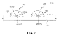
- FIG. 2 is a cross-sectional view illustrating a white light emitting device and a white light source module according to an exemplary embodiment of the invention
- FIG. 3 is a cross-sectional view illustrating a white light emitting device and a white light source module according to an exemplary embodiment of the invention
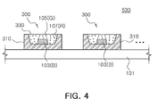
- FIG. 4 is a cross-sectional view illustrating a white light emitting device and a white light source module according to an exemplary embodiment of the invention
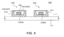
- FIG. 5 is a cross-sectional view illustrating a white light emitting device and a white light source module according to an exemplary embodiment of the invention
- FIG. 6 illustrates a color coordinate space of phosphors used in a white light emitting device according to an exemplary embodiment of the invention.
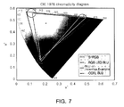
- FIG. 7 illustrates a color coordinate range obtained in a case where white light source modules of Inventive Example and Comparative Example are employed in a backlight unit of a liquid crystal display (LCD).
- LCD liquid crystal display
- FIG. 2 is a schematic cross-sectional view illustrating a white light emitting device and a white light source module using the same according to an exemplary embodiment of the invention.
- the white light source module 510 includes a circuit board 101 such as a printed circuit board, and at least one white light emitting device 100 disposed on the circuit board 101.
- the white light emitting device 100 includes a blue B light emitting diode (LED) chip 103, a green G phosphor 105 and a red R phosphor 107.
- the green phosphor 105 and the red phosphor 107 are excited by the blue LED chip 103 to emit green light and red light, respectively.
- the green light and the red light are mixed with a portion of the blue light from the blue LED chip 103 to produce white light.
- LED blue B light emitting diode
- the blue LED chip 103 is directly mounted on the circuit board 101 and the phosphors 105 and 107 are dispersed and mixed uniformly in a resin encapsulant 130 encapsulating the blue LED chip 103.
- the resin encapsulant 130 may be formed, for example, in a semi-circle which serves as a kind of lens.
- the resin encapsulant 130 may be formed of one of an epoxy resin, a silicone resin and a hybrid resin.
- the blue LED chip 103 is directly mounted on the circuit board 101 by a chip-on-board technique, thereby allowing the white light emitting device 100 to achieve a greater view angle more easily.
- This white light source module 510 may include a plurality of the white light emitting devices 100 to form a surface or line light source with a desired area, thereby beneficially utilized as a light source of a backlight unit of the LCD device.
- the inventors of the present invention have defined a dominant wavelength of the blue LED chip 103 to be in a specific range and a color coordinate of the red and green phosphors 105 and 107 to be within a specific space based on the CIE 1931 color chromaticity diagram. This enabled the inventors to realize maximum color reproducibility from a combination of the green and red phosphors and the blue LED chip.
- the blue LED chip 103 has a dominant wavelength of 443 to 455nm.
- the red light emitted from the red phosphor 107 excited by the blue LED chip 103 has a color coordinate falling within a space defined by four coordinate points (0.5448, 0.4544), (0.7079, 0.2920), (0.6427, 0.2905) and (0.4794, 0.4633) based on the CIE 1931 (x, y) color chromaticity diagram.
- the green light emitted from the green phosphor excited by the blue LED chip 103 has a color coordinate falling within a space defined by (0.1270, 0.8037), (0.4117, 0.5861), (0.4197, 0.5316) and (0.2555, 0.5030) based on the CIE 1931 color chromaticity diagram.
- FIG. 6 illustrates color coordinate spaces of the red and green phosphors described above.
- the CIE 1931 color chromaticity diagram is marked with a quadrilateral-shaped space r composed of four coordinate points (0.5448, 0.4544), (0.7079, 0.2920), (0.6427, 0.2905) and (0.4794, 0.4633) and a quadrilateral-shaped space g composed of four coordinate points (0.1270, 0.8037), (0.4117, 0.5861), (0.4197, 0.5316) and (0.2555, 0.5030).
- the red phosphor and green phosphor are selected such that color coordinates thereof fall within the quadrilateral-shaped spaces r and g, respectively.
- a dominant wavelength is a wavelength value derived from a curve obtained by integrating an actually-measured spectrum graph of an output light of the blue LED chip and a luminosity curve.
- the dominant wavelength is a value considering visibility of a person. This dominant wavelength corresponds to a wavelength value at a point where a line connecting a center point (0.333, 0.333) of the CIE 1976 color chromaticity diagram to the actually-measured color coordinate meets a contour line of the CIE 1976 chromaticity diagram.
- a peak wavelength is different from the dominant wavelength.
- the peak wavelength has the highest energy intensity.
- the peak wavelength is a wavelength value indicating the highest intensity in the spectrum graph of the actually-measured output light, regardless of luminosity.
- the blue LED chip 103 has a dominant wavelength of 443 to 455nm.
- the red phosphor 107 has a color coordinate falling within a quadrilateral space defined by four coordinate points (0.5448, 0.4544), (0.7079, 0.2920), (0.6427, 0.2905) and (0.4794, 0.4633), based on the CIE 1931 color chromaticity diagram.
- the green phosphor 105 has a color coordinate falling within a quadrilateral space defined by four coordinate points (0.1270, 0.8037), (0.4117, 0.5861), (0.4197, 0.5316) and (0.2555, 0.5030).
- a liquid crystal display (LCD) device employing the white light source module 510 for a backlight unit may exhibit high color reproducibility across a very large color coordinate space covering a substantially entire s-RGB space on the CIE 1976 chromaticity diagram (see FIG. 7 ). This high color reproducibility is hardly attainable from a conventional combination of a blue LED chip and red and green phosphors.
- the blue LED chip and red and green phosphors falling outside the dominant wavelength range and color coordinate space as described above may degrade color reproducibility or color quality of the LCD.
- the blue LED chip used along with the red and green phosphors to obtain white light has a dominant wavelength of typically 460nm or more.
- the blue light has a shorter dominant wavelength than the conventional one and the red and green phosphors have a color coordinate falling within the quadrilateral space as described above, thereby producing higher color reproducibility which is hardly achieved by the prior art.
- the blue LED chip 103 may adopt a group-III nitride semiconductor LED device in general use.
- the red phosphor 107 may utilize a nitride phosphor such as CaAlSiN 3 :Eu.
- This nitride red phosphor is less vulnerable to the external environment such as heat and moisture than a yellow phosphor, and less likely to be discolored.
- the nitride red phosphor exhibits high excitation efficiency with respect to the blue LED chip having a dominant wavelength set to a specific range of 443 to 455nm to obtain high color reproducibility.
- the green phosphor 105 may adopt a silicate phosphor such as A 2 SiO 4 :Eu where A is at least one of Ba, Sr and Ca.
- the green phosphor 105 may employ (Ba, Sr) 2 SiO 4 :Eu.
- the silicate phosphor demonstrates high excitation efficiency with respect to the blue LED chip having a dominant wavelength of 443 to 455nm.
- one of SrGa 2 S 4 :Eu and ⁇ -SiAlON(Beta-SiAlON) may be utilized as the green phosphor 105.
- the blue LED chip 103 has a full width at half maximum (FWHM) of 10 to 30nm
- the green phosphor 105 has a FWHM of 30 to 100nm
- the red phosphor 107 has a FWHM of 50 to 200nm.
- the light sources 103, 105, and 107 with the FWHM ranging as described above produces white light of better color uniformity and higher color quality.
- the blue LED chip 103 having a dominant wavelength of 443 to 455 nm and a FWHM of 10 to 30nm significantly enhances excitation efficiency of the CaAlSiN 3 :Eu or (Ca,Sr)S:Eu red phosphor and the A 2 SiO4:Eu, SrGa 2 S 4 :Eu, or ⁇ -SiAlON green phosphor.
- a in A 2 SiO 4 :Eu is at least one of Ba, Sr, and Ca.
- the blue LED chip has a dominant wavelength of a predetermined range and the green and red phosphors have color coordinates within a predetermined space. This allows superior color reproducibility than a conventional combination of the blue LED chip and yellow phosphor, and than a conventional combination of the blue LED chip and green and red phosphors, respectively. This also improves excitation efficiency and overall light efficiency as well.
- the present embodiment unlike the conventional white light source module using the red, green and blue LED chips, a fewer number of LED chips are required and only one type of the LED chip, i.e., blue LED chip is required. This accordingly reduces manufacturing costs for packages and simplifies a driving circuit. Notably, an additional circuit may be configured with relative simplicity to increase contrast or prevent blurring. Also, only one LED chip 103 and the resin encapsulant encapsulating the LED chip 103 allow white light of a unit area to be emitted, thereby ensuring superior color uniformity to a case where the red, green and blue LED chips are employed.
- FIG. 3 is schematic cross-sectional view illustrating a white light emitting device 200 and a white light source module 520 using the same.
- a blue LED chip 103 is directly mounted on a circuit board 101 by a chip-on-board technique.
- the blue LED chip 103 constitutes the white light emitting device 200 of a unit area together with a red phosphor and a green phosphor excited by the blue LED chip 103.
- the blue LED chip 103 has a dominant wavelength range, and the red phosphor and green phosphor have a color coordinate space as described above, respectively. That is, the blue LED chip 103 has a dominant wavelength of 443 to 455nm.
- the red phosphor has a color coordinate falling within a quadrilateral space defined by four coordinate points (0.5448, 0.4544), (0.7079, 0.2920), (0.6427, 0.2905) and (0.4794, 0.4633) on the CIE 1931 color chromaticity diagram.
- the green phosphor has a color coordinate falling within a quadrilateral space defined by four coordinate points (0.1270, 0.8037), (0.4117, 0.5861), (0.4197, 0.5316) and (0.2555, 0.5030).
- the red and green phosphors are not dispersed and mixed in a resin encapsulant but provided as a phosphor film.
- a green phosphor film 205 containing the green phosphor is thinly applied along a surface of the blue LED chip 103 and a semi-circular transparent resin encapsulant 230 is formed on the green phosphor film 205.
- a red phosphor film 207 containing the red phosphor is applied on a surface of the transparent resin encapulant 230.
- the green phosphor film 205 and the red phosphor film 207 may be located reversely with each other.
- the red phosphor film 207 may be applied on the blue LED chip 103 and the green phosphor film 205 may be applied on the resin encapsulant 230.
- the green phosphor film 205 and the red phosphor film 207 may be formed of a resin containing green phosphor particles and red phosphor particles, respectively.
- the phosphors contained in the phosphor films 207 and 205 may employ one of a nitride, a yellow phosphor and a silicate phosphor as described above.
- the green phosphor film 205, the transparent resin encapsulant 230, and the red phosphor film 207 are formed to further enhance color uniformity of white light outputted.
- the green and red phosphors are merely dispersed in the resin encapsulant, the phosphors are not uniformly distributed due to difference in weight between the phosphors during resin curing, thus risking a problem of layering. This may reduce color uniformity in a single white light emitting device.
- the blue light emitted at various angles from the blue LED chip 103 are relatively uniformly absorbed or transmitted through the phosphor films 205 and 207, thereby producing more uniform white light overall. That is, color uniformity is additionally enhanced.
- the phosphor films 205 and 207 separate from each other by the transparent resin encapsulant 230 may lower phosphor-induced optical loss.
- secondary light (green light or red light) wavelength-converted by the phosphor is scattered by phosphor particles present on an optical path, thereby causing optical loss.
- the secondary light wavelength-converted by the thin green or red phosphor film 205 or 207 passes through the transparent resin encapsulant 230 or is emitted outside the light emitting device 200, thereby lowering optical loss resulting from the phosphor particles.
- the blue LED chip has a dominant wavelength range, and the green and red phosphors have color coordinate space as described above, respectively. Accordingly, the white light source module 520 for the BLU of the LCD exhibits high color reproducibility across a very large space covering a substantially entire s-RGB space. This also reduces the number of the LED chips, and manufacturing costs for driving circuits and packages, thereby realizing lower unit costs.
- the blue, green and red light may have a FWAH ranging as described above.
- each of LED chips is directly mounted on the circuit board by a COB technique.
- the present invention is not limited thereto.
- the LED chip may be mounted inside a package body mounted on the circuit board.
- FIGS. 4 and 5 illustrate additional package bodies employed according to an exemplary embodiment of the invention, respectively.
- FIG. 4 is a cross-sectional view illustrating a white light emitting device 300 and a white light source module 530 using the same according to an exemplary embodiment of the invention.
- a package body 310 defining a reflective cup is mounted on a circuit board 101.
- a blue B LED chip 103 is disposed on a bottom of the reflective cup defined by the package body 310 and a resin encapsulant 330 having a green R phosphor 105 and a red G phosphor 107 dispersed therein encapsulates the LED chip 103.
- a plurality of the white light emitting devices 300 i.e. , a plurality of the LED packages may be arranged on the board 101.
- the blue LED chip has a dominant wavelength range, and the red and green phosphors have color coordinate spaces as described above, respectively, thereby assuring high color reproducibility. Furthermore, the number of the LED chips, and manufacturing costs for driving circuits and packages are declined to realize lower unit costs.
- FIG. 5 is a schematic cross-sectional view illustrating a white light emitting device and a white light source module 540 using the same according to an exemplary embodiment of the invention.
- the white light emitting device 400 includes a package body 410 defining a reflective cup and a blue LED chip 103 mounted on the reflective cup.
- the red and green phosphors are not dispersed and mixed in a resin encapsulant and provided as a phosphor film. That is, one of a green phosphor 405 and a red phosphor 407 is applied along a surface of the blue LED chip 103 and a transparent resin encapsulant 430 is formed thereon. Also, the other one of the green and red phosphors 405 and 407 is applied along a surface of the transparent resin encapsulant 430.
- the green phosphor film 405 and the red phosphor film 407 separated from each other by the resin encapsulant 430 are employed to ensure superior color uniformity.
- the blue LED chip has a dominant wavelength range and the red and green phosphors have color coordinate spaces as described above, thereby producing high color reproducibility across a very large space covering a substantially entire s-RGB space.
- FIG. 7 illustrates the CIE 1976 chromatic diagram indicating color coordinate ranges obtained in a case where white light source modules of Inventive Example and Comparative Example are employed in BLUs of LCDs, respectively.
- the white light source module of Inventive Example emits white light by a combination of a blue LED chip, a red phosphor and a green phosphor (see FIG. 4 ).
- the blue LED chip has a dominant wavelength of 443 to 455nm, particularly 451nm.
- the red phosphor emits red light having a color coordinate falling within a quadrilateral space defined by four coordinate points (0.5448, 0.4544), (0.7079, 0.2920), (0.6427, 0.2905) and (0.4794, 0.4633) based on the CIE 1931 color chromaticity diagram.
- the green phosphor emits green light having a color coordinate falling within a quadrilateral space defined by (0.1270, 0.8037), (0.4117, 0.5861), (0.4197, 0.5316) and (0.2555, 0.5030) based on the CIE 1931 color chromaticity diagram.
- the white light source module of Comparative Example 1 emits white light by a combination of red, green and blue LED chips. Also, a white light source module of Comparative Example 2 emits white light using a conventional cold cathode fluorescent lamp.
- the chromaticity diagram of FIG. 7 indicates a color coordinate space of the LCD employing the light source module of Inventive Example as the BLU, and a color coordinate space of the LCDs employing the light sources of Comparative Example 1 and Comparative Example 2 as the BLUs, respectively.
- the LCD adopting the BLU according to Inventive Example exhibits a very broad color coordinate space covering a substantially entire s-RGB space. This high color reproducibility is not attainable by a conventional combination of a blue LED chip, red and green phosphors.
- the LCD utilizing the BLU (RGB LED BLUE) according to Comparative Example 1 employs only the LED chips as red, green and blue light sources, thus demonstrating a broad color coordinate space.
- the LCD adopting the RGB LED BLU according to Comparative Example 1 disadvantageously does not exhibit a blue color in the s-RGB space.
- only three-color LED chips employed without phosphors degrade color uniformity, while increasing the number of the LED chips required and manufacturing costs. Notably, this entails complicated configuration of an additional circuit for contrast increase or local dimming, and drastic increase in costs for the circuit configuration.
- the LCD employing the BLU (CCFL BLU) of Comparative Example 2 exhibits a relatively narrow color coordinate space, thus lowered in color reproducibility over the BLUs of Inventive Example and Comparative Example 1, respectively.
- the CCFL BLU is not environment-friendly and can be hardly configured in a circuit for improving its performance such as local dimming and contrast adjustment.
- a blue LED chip having a dominant wavelength of a specific range, and red and green phosphors having a color coordinate of a specific space, respectively, are employed.
Landscapes
- Led Device Packages (AREA)
Priority Applications (3)
| Application Number | Priority Date | Filing Date | Title |
|---|---|---|---|
| EP20080250974 EP2104149A1 (de) | 2008-03-19 | 2008-03-19 | Lichtemittierende Vorrichtung von weißem Licht und Weißlichtquellenmodul damit |
| DE202008018060U DE202008018060U1 (de) | 2008-03-19 | 2008-03-19 | Weißlicht-emittierende Vorrichtung und Weißlichtquellenmodul, das diese Vorrichtung verwendet |
| EP20110157877 EP2328190A3 (de) | 2008-03-19 | 2008-03-19 | Lichtemittierende Vorrichtung von weißem Licht und Weißlichtquellenmodul damit |
Applications Claiming Priority (1)
| Application Number | Priority Date | Filing Date | Title |
|---|---|---|---|
| EP20080250974 EP2104149A1 (de) | 2008-03-19 | 2008-03-19 | Lichtemittierende Vorrichtung von weißem Licht und Weißlichtquellenmodul damit |
Publications (1)
| Publication Number | Publication Date |
|---|---|
| EP2104149A1 true EP2104149A1 (de) | 2009-09-23 |
Family
ID=39687037
Family Applications (2)
| Application Number | Title | Priority Date | Filing Date |
|---|---|---|---|
| EP20080250974 Ceased EP2104149A1 (de) | 2008-03-19 | 2008-03-19 | Lichtemittierende Vorrichtung von weißem Licht und Weißlichtquellenmodul damit |
| EP20110157877 Ceased EP2328190A3 (de) | 2008-03-19 | 2008-03-19 | Lichtemittierende Vorrichtung von weißem Licht und Weißlichtquellenmodul damit |
Family Applications After (1)
| Application Number | Title | Priority Date | Filing Date |
|---|---|---|---|
| EP20110157877 Ceased EP2328190A3 (de) | 2008-03-19 | 2008-03-19 | Lichtemittierende Vorrichtung von weißem Licht und Weißlichtquellenmodul damit |
Country Status (2)
| Country | Link |
|---|---|
| EP (2) | EP2104149A1 (de) |
| DE (1) | DE202008018060U1 (de) |
Cited By (13)
| Publication number | Priority date | Publication date | Assignee | Title |
|---|---|---|---|---|
| EP2312659A3 (de) * | 2009-10-15 | 2011-06-29 | LG Innotek Co., Ltd. | Lichtemittierende Vorrichtung |
| WO2013093750A1 (en) * | 2011-12-19 | 2013-06-27 | Koninklijke Philips Electronics N.V. | Light source using remote phosphor and pink led |
| EP2400567A3 (de) * | 2010-06-25 | 2016-06-22 | Panasonic Intellectual Property Management Co., Ltd. | Phosphorauswahl für eine Licht-emittierende Vorrichtung |
| JP2016531432A (ja) * | 2013-08-01 | 2016-10-06 | フィリップス ライティング ホールディング ビー ヴィ | 適合された出力スペクトルを持つ発光装置 |
| US20190074411A1 (en) * | 2017-09-07 | 2019-03-07 | Ledvance Gmbh | Light-emitting component, light fixture, method for operating a light fixture, and conversion element |
| US10479936B2 (en) | 2016-08-12 | 2019-11-19 | Osram Opto-Semiconductors Gmbh | Phosphor and method for producing the phosphor |
| US10505080B2 (en) | 2016-08-12 | 2019-12-10 | Osram Opto Semiconductors Gmbh | Lighting device |
| US10519371B2 (en) | 2016-11-11 | 2019-12-31 | Osram Opto Semiconductors Gmbh | Phosphor, illumination device and use of an illumination device |
| US10644206B2 (en) | 2016-08-12 | 2020-05-05 | Osram Oled Gmbh | Lighting device |
| US10711192B2 (en) | 2016-08-12 | 2020-07-14 | Osram Oled Gmbh | Lighting device |
| US11230664B2 (en) | 2016-11-11 | 2022-01-25 | Osram Oled Gmbh | Dimmable light source |
| US11447695B2 (en) | 2017-11-10 | 2022-09-20 | Osram Oled Gmbh | Lighting device and use of lighting device |
| US11542431B2 (en) | 2017-11-10 | 2023-01-03 | Osram Oled Gmbh | Luminophore combination, conversion element, and optoelectronic device |
Families Citing this family (2)
| Publication number | Priority date | Publication date | Assignee | Title |
|---|---|---|---|---|
| TWI469396B (zh) | 2014-07-01 | 2015-01-11 | Unity Opto Technology Co Ltd | Applied to the backlight of the LED light-emitting structure |
| DE102015120775B4 (de) | 2015-11-30 | 2025-04-30 | OSRAM Opto Semiconductors Gesellschaft mit beschränkter Haftung | Optoelektronisches Bauelement und Hintergrundbeleuchtung für ein Display |
Citations (2)
| Publication number | Priority date | Publication date | Assignee | Title |
|---|---|---|---|---|
| EP1566848A2 (de) | 2004-02-23 | 2005-08-24 | LumiLeds Lighting U.S., LLC | Leuchtdiode mit Wellenlängen-Konversion |
| WO2006121196A1 (en) * | 2005-05-12 | 2006-11-16 | Matsushita Electric Industrial Co., Ltd. | Led with a phosphor layer having different thikness or different phosphor concentration |
Family Cites Families (2)
| Publication number | Priority date | Publication date | Assignee | Title |
|---|---|---|---|---|
| KR101019765B1 (ko) * | 2006-01-04 | 2011-03-04 | 로무 가부시키가이샤 | 박형 발광 다이오드 램프와 그 제조 방법 |
| KR100771772B1 (ko) * | 2006-08-25 | 2007-10-30 | 삼성전기주식회사 | 백색 led 모듈 |
-
2008
- 2008-03-19 DE DE202008018060U patent/DE202008018060U1/de not_active Expired - Lifetime
- 2008-03-19 EP EP20080250974 patent/EP2104149A1/de not_active Ceased
- 2008-03-19 EP EP20110157877 patent/EP2328190A3/de not_active Ceased
Patent Citations (2)
| Publication number | Priority date | Publication date | Assignee | Title |
|---|---|---|---|---|
| EP1566848A2 (de) | 2004-02-23 | 2005-08-24 | LumiLeds Lighting U.S., LLC | Leuchtdiode mit Wellenlängen-Konversion |
| WO2006121196A1 (en) * | 2005-05-12 | 2006-11-16 | Matsushita Electric Industrial Co., Ltd. | Led with a phosphor layer having different thikness or different phosphor concentration |
Non-Patent Citations (2)
| Title |
|---|
| HIROSAKI NAOTO ET AL.: "Characterization and properties of green- emitting[beta]-SiAION:Eu2+ powder phosphors for white light-emitting diodes", APPLIED PHYSICS LETTERS, vol. 86, no. 21, 17 May 2005 (2005-05-17), pages 211905 - 211905 |
| HIROSAKI NAOTO ET AL: "Characterization and properties of green-emitting[beta]-SiAlON:Eu2+ powder phosphors for white light-emitting diodes", APPLIED PHYSICS LETTERS, AIP, AMERICAN INSTITUTE OF PHYSICS, MELVILLE, NY, US, vol. 86, no. 21, 17 May 2005 (2005-05-17), pages 211905 - 211905, XP012065627, ISSN: 0003-6951, DOI: 10.1063/1.1935027 * |
Cited By (23)
| Publication number | Priority date | Publication date | Assignee | Title |
|---|---|---|---|---|
| EP2312659A3 (de) * | 2009-10-15 | 2011-06-29 | LG Innotek Co., Ltd. | Lichtemittierende Vorrichtung |
| US8946743B2 (en) | 2009-10-15 | 2015-02-03 | Lg Innotek Co., Ltd. | Light emitting apparatus |
| US9683715B2 (en) | 2009-10-15 | 2017-06-20 | Lg Innotek Co., Ltd. | Light emitting apparatus |
| EP2400567A3 (de) * | 2010-06-25 | 2016-06-22 | Panasonic Intellectual Property Management Co., Ltd. | Phosphorauswahl für eine Licht-emittierende Vorrichtung |
| WO2013093750A1 (en) * | 2011-12-19 | 2013-06-27 | Koninklijke Philips Electronics N.V. | Light source using remote phosphor and pink led |
| CN104011456A (zh) * | 2011-12-19 | 2014-08-27 | 皇家飞利浦有限公司 | 利用远程荧光体和粉光led的光源 |
| US9097397B2 (en) | 2011-12-19 | 2015-08-04 | Koninklijke Philips N.V. | Light source using remote phosphor and pink LED |
| JP2016531432A (ja) * | 2013-08-01 | 2016-10-06 | フィリップス ライティング ホールディング ビー ヴィ | 適合された出力スペクトルを持つ発光装置 |
| US10479936B2 (en) | 2016-08-12 | 2019-11-19 | Osram Opto-Semiconductors Gmbh | Phosphor and method for producing the phosphor |
| US11639465B2 (en) | 2016-08-12 | 2023-05-02 | Osram Oled Gmbh | Phosphor and method for producing the phosphor |
| US10505080B2 (en) | 2016-08-12 | 2019-12-10 | Osram Opto Semiconductors Gmbh | Lighting device |
| US10644206B2 (en) | 2016-08-12 | 2020-05-05 | Osram Oled Gmbh | Lighting device |
| US10711192B2 (en) | 2016-08-12 | 2020-07-14 | Osram Oled Gmbh | Lighting device |
| US11566174B2 (en) | 2016-08-12 | 2023-01-31 | Osram Oled Gmbh | Phosphor and method for producing the phosphor |
| US11453822B2 (en) | 2016-08-12 | 2022-09-27 | Osram Oled Gmbh | Lighting device |
| US11230664B2 (en) | 2016-11-11 | 2022-01-25 | Osram Oled Gmbh | Dimmable light source |
| US10519371B2 (en) | 2016-11-11 | 2019-12-31 | Osram Opto Semiconductors Gmbh | Phosphor, illumination device and use of an illumination device |
| US10811571B2 (en) * | 2017-09-07 | 2020-10-20 | Ledvance Gmbh | Light-emitting component, light fixture, method for operating a light fixture, and conversion element |
| CN109473534B (zh) * | 2017-09-07 | 2021-07-13 | 朗德万斯公司 | 发光元件、发光装置、用于运行发光装置的方法以及转换元件 |
| CN109473534A (zh) * | 2017-09-07 | 2019-03-15 | 朗德万斯公司 | 发光元件、发光装置、用于运行发光装置的方法以及转换元件 |
| US20190074411A1 (en) * | 2017-09-07 | 2019-03-07 | Ledvance Gmbh | Light-emitting component, light fixture, method for operating a light fixture, and conversion element |
| US11447695B2 (en) | 2017-11-10 | 2022-09-20 | Osram Oled Gmbh | Lighting device and use of lighting device |
| US11542431B2 (en) | 2017-11-10 | 2023-01-03 | Osram Oled Gmbh | Luminophore combination, conversion element, and optoelectronic device |
Also Published As
| Publication number | Publication date |
|---|---|
| EP2328190A3 (de) | 2011-06-15 |
| EP2328190A2 (de) | 2011-06-01 |
| DE202008018060U1 (de) | 2011-05-12 |
Similar Documents
| Publication | Publication Date | Title |
|---|---|---|
| US7964885B2 (en) | White light emitting device and white light source module using the same | |
| EP2104149A1 (de) | Lichtemittierende Vorrichtung von weißem Licht und Weißlichtquellenmodul damit | |
| CN101216150B (zh) | 白光发射装置及使用其的用于液晶显示器背光的光源模块 | |
| TWI455374B (zh) | 白光發光二極體模組 | |
| KR101907390B1 (ko) | 백색 발광 장치 및 이를 이용한 디스플레이 장치 | |
| KR20050098462A (ko) | 형광체 및 이를 이용한 백색 발광다이오드 | |
| KR20130010283A (ko) | 백색 발광 장치 및 이를 이용한 디스플레이 및 조명장치 | |
| JP2011228344A (ja) | Led発光装置 | |
| CN104810357A (zh) | 一种显示器、背光模组及led光源装置 | |
| CN101840987A (zh) | 白光发射装置以及使用该白光发射装置的白光源模块 | |
| KR101195430B1 (ko) | 백색 발광장치 및 이를 이용한 백색 광원 모듈 | |
| CN101546797A (zh) | 白光发射装置以及使用该白光发射装置的白光源模块 | |
| JP2007036041A (ja) | 発光装置及び光学装置 | |
| KR101564067B1 (ko) | 색재현율 개선제를 이용한 디스플레이 백라이트 유닛(blu)용 발광다이오드 소자 | |
| KR100990647B1 (ko) | 백색 발광장치 및 이를 이용한 백색 광원 모듈 | |
| KR101942253B1 (ko) | 형광체 및 이를 구비한 발광 다이오드 패키지 | |
| CN121419411A (zh) | 光致发光波长转换发光装置 | |
| KR20130079803A (ko) | 백색 발광 장치 및 이를 이용한 디스플레이 및 조명장치 | |
| KR20090004344A (ko) | 백색 led 장치 |
Legal Events
| Date | Code | Title | Description |
|---|---|---|---|
| PUAI | Public reference made under article 153(3) epc to a published international application that has entered the european phase |
Free format text: ORIGINAL CODE: 0009012 |
|
| 17P | Request for examination filed |
Effective date: 20080331 |
|
| AK | Designated contracting states |
Kind code of ref document: A1 Designated state(s): AT BE BG CH CY CZ DE DK EE ES FI FR GB GR HR HU IE IS IT LI LT LU LV MC MT NL NO PL PT RO SE SI SK TR |
|
| AX | Request for extension of the european patent |
Extension state: AL BA MK RS |
|
| 17Q | First examination report despatched |
Effective date: 20100429 |
|
| AKX | Designation fees paid |
Designated state(s): AT BE BG CH CY CZ DE DK EE ES FI FR GB GR HR HU IE IS IT LI LT LU LV MC MT NL NO PL PT RO SE SI SK TR |
|
| RAP1 | Party data changed (applicant data changed or rights of an application transferred) |
Owner name: SAMSUNG LED CO., LTD. |
|
| RAP1 | Party data changed (applicant data changed or rights of an application transferred) |
Owner name: SAMSUNG ELECTRONICS CO., LTD. |
|
| STAA | Information on the status of an ep patent application or granted ep patent |
Free format text: STATUS: THE APPLICATION HAS BEEN REFUSED |
|
| 18R | Application refused |
Effective date: 20140215 |